SERVICE MANUAL
Plasma Color Television
42HP84
FILE NO. 020-200417
DOCUMENT CREATED IN JAPAN, Oct., 2004

- 2 -
TABLE OF CONTENTS
SERVICE SAFETY PRECAUTIONS .................................................................................................................................... 3
IMPORTANT INFORMATION ............................................................................................................................................... 5
CLEANING ........................................................................................................................................................................... 6
SERVICE MODE .................................................................................................................................................................. 7
TROUBLESHOOTING DIAGNOSIS FUNCTION ................................................................................................................
............................................................................................................................................
8
LOCATION OF CONTROLS ...........................................................................................................
..................................... 11
10
LAYOUT OF MAJOR BOARDS .........................................................................................................
................................... 13
MECHANICAL DISASSEMBLY .......................................................................................................................................... 14
EXPLODED VIEW ............................................................................................................................................................. 17
PACKING DISASSEMBLY .................................................................................................................................................. 19
CHASSIS AND CABINET REPLACEMENT PARTS LIST ................................................................................................. 20
PC BOARDS TOP & BOTTOM VIEW ............................................................................................................................... 27
BLOCK DIAGRAM ............................................................................................................................................................. 43
SPECIFICATIONS .......................................................................................................................................................... END
APPENDIX:
SCHEMATIC DIAGRAM
ELECTRICAL ADJUSTMENTS

- 3 -
GENERAL
ADJUSTMENTS
SPECIFIC
INFORMATIONS
SERVICE SAFETY PRECAUTIONS
· The caution items shown here describe major safety issues and should always be observed.
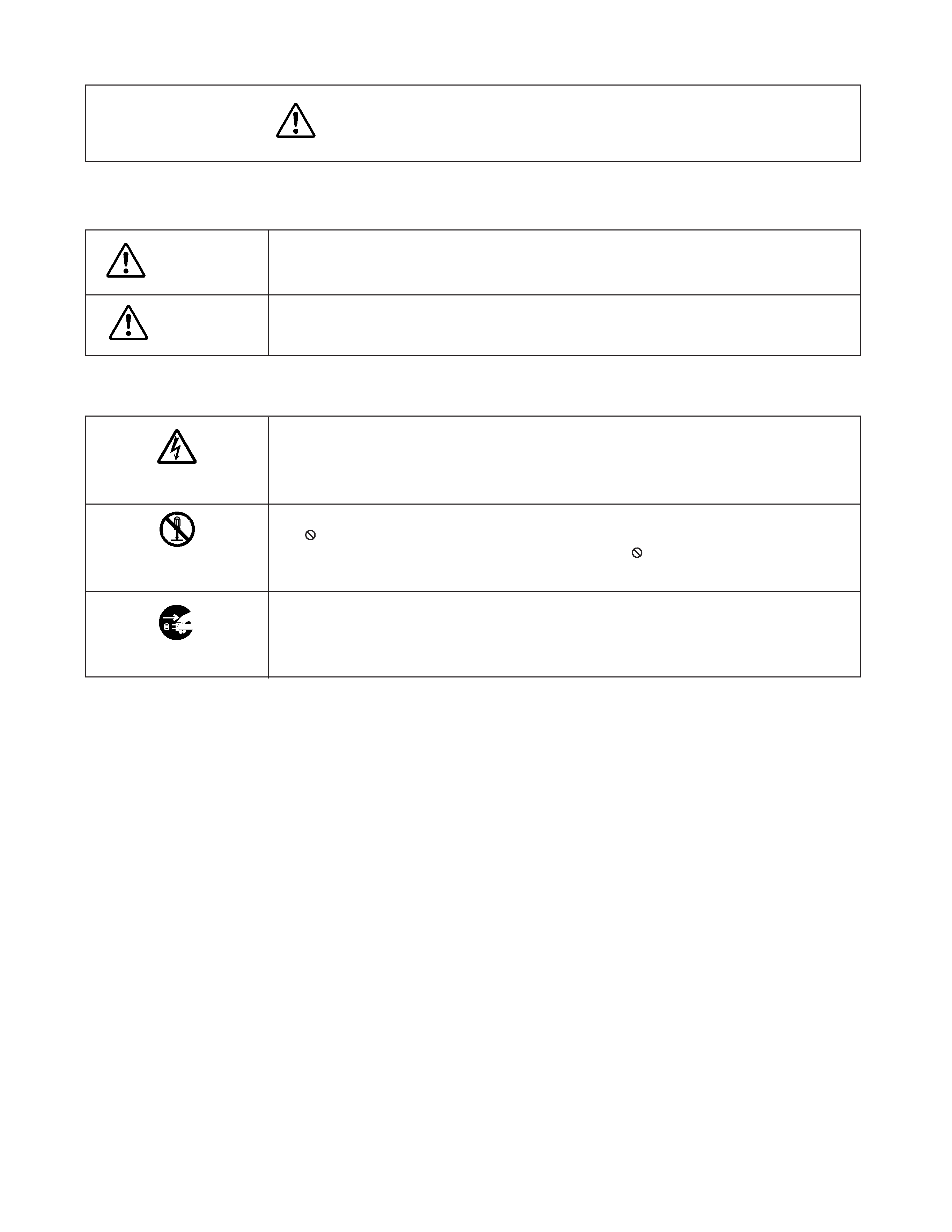
· The meanings of the various indications are as follows.
WARNING
CAUTION
Indicates a hypothetical situation in which service personnel and nearby third parties, or even
end users due to a product defect after the service operation is completed, could possibly be in
danger of injury or even death in the event of operational error.
Indicates a hypothetical situation in which service personnel and nearby third parties, or even
end users after the service operation is completed, could possibly be in danger of injury, or
where there could be physical damage in the event of operational error.
* Physical damage means major damage to a home, furnishings and other possessions.
Examples of marks
SHOCK HAZARD
PROHIBIT DISASSEM-
BLING
UNPULUG
The
" indicates caution (including danger and warning).
The actual meaning of this caution is indicated inside the
" or nearby illustrations or text.
The example shown to the left indicates the danger of "electrical shock".
The
indicates a forbidden action.
The actual meaning of this caution is indicated inside the
or nearby illustrations or text.
The example shown to the left indicates that disassembly is forbidden.
The
- indicates a forced action (an action that must be performed).
The actual meaning of this forced action is indicated by
- or nearby illustrations or text.
The example shown to the left indicates that the power plug must be disconnected.

- 4 -
GENERAL
ADJUSTMENTS
SPECIFIC
INFORMATIONS
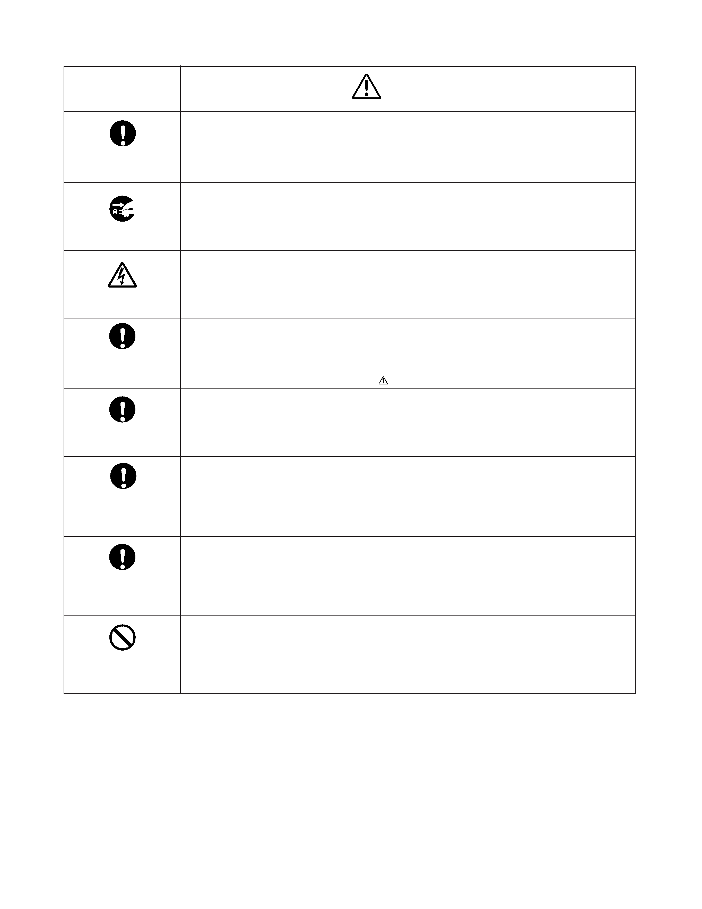
WARNING
KEEP CHILDREN
AWAY
UNPULUG
SHOCK HAZARD
USE SPECIFIED
PARTS
CAUTION FOR
WIRING
CAUTION FOR
ASSEMBLING /
WIRING
CHECK INSULATION
RESISTANCE
PROHIBIT
REMODELING
· Always advise users to keep children away.
There is danger of injury to children from tools, disassembled products, etc.
· Always disconnect the power plug before starting work whenever power is not required.
Failure to disconnect the power plug before starting work can result in electrical shock.
· Depending on the model, use an insulation transformer or wear gloves when servicing with the
power on, and disconnect the power plug to avoid electrical shock when replacing parts.
In some cases, alternating current is also impressed in the chassis, so electrical shock is pos-
sible if the chassis is contacted with the power on.
· Always use the replacement parts specified for the particular model when making repairs.
The parts used in products have the necessary safety characteristics such as inflammability,
voltage resistance, etc.; therefore, use only replacement parts that have these same character-
istics.
Use only the specified parts when the
mark is included in a circuit diagram or parts list.
· Parts mounting and routing of the wiring should be the same as that used originally.
For safety purposes, insulating materials such as tubing or tape is sometimes used and printed
circuit boards are sometimes mounted floating.
Also make sure that wiring is routed and clamped to avoid parts that generate heat and which
use high voltage. Always follow the original scheme.
· After a repair has been completed, reassemble all disassembled parts, and route and recon-
nect the wiring, in accordance with the original scheme.
Do not allow internal wiring to be pinched by cabinets, panels, etc.
Any error in reassembly or wiring can result in electrical leakage, flame, etc., and may be
hazardous.
· After completing the work, disconnect the power plug from the outlet, remove the antenna, turn
on the power switch. Then, use a 500V insulation resistance meter to check the insulation
resistance of the antenna terminal, other metallic parts and between the prongs of the power
plug to make sure that the insulation resistance is 1M
or more.
The set will require inspection and repair if the insulation resistance is below this value.
· Never remodel the product in any way.
Remodeling can result in improper operation, malfunction, or electrical leakage and flame,
which may be hazardous

- 5 -
GENERAL
ADJUSTMENTS
SPECIFIC
INFORMATIONS
IMPORTANT INFORMATION
About Permanent after-image
· Due to the characteristics of a plasma screen, if the same image is displayed for an extended period
of time, permanent after-image (image retention) in part of the screen may result. As a result of accu-
mulative effect, brightness deterioration results.
To prevent permanent after-image, it is recommended not to display the same image for an extended
period of time, or in 4:3 mode. If retention occurs, display a moving picture like a video movie. This may
help to reduce minor permanent after-image. But it cannot be removed entirely once it has occurred. If
the same static picture is displayed frequently, it is recommended to decrease "Brightness," or to
adjust the Long life setting.
Note on operations in 4:3 mode
· In 4:3 mode, because of the sharp contrast between the displayed image area and non-displayed image area (frame),
permanent after-image is likely to result.
Therefore, we recommend adjusting the TV settings as follows:
1. Reduce "Contrast" and "Brightness" of the picture. The more you reduce, the more effect is effective.
2. Adjust the brightness of the side panels. The more you turn the brightness high, the more effect is effective.
However, after adjusting the above settings, permanent after-image may not be removed entirely; only the onset of after-
image is delayed. Display your TV in Super Live or Wide mode as much as possible.
Some parts of the screen do not light up
· The plasma display panel is manufactured using an extremely high level of precision technology, however sometimes
some parts of the screen may be missing picture elements or have luminous spots. This is not a sign of a malfunction.
About infrared rays
· The plasma screen of this unit emits infrared rays in normal operation, and may influence some infrared-operated equip-
ment by a use state although the measures of infrared ray (filter, etc.) are taken. Locate such equipment carefully to
prevent rays from the plasma screen causing any problems.
About Interference
· Plasma display may cause interference in image, sound, etc. of other electronic equipment that is easy to receive electro-
magnetic waves (i.e. AM radios and video equipment) under certain installed condition. In particular, it may affect elec-
tronic equipment beyond the residential unit where a plasma display TV is used.
About Static electricity
· If you touch the surface of the screen panel, you may feel a slight electric shock. This is harmless.
About using under the low temperature places
· If you use the TV in the room of 0
°C or less, the picture brightness may vary until the plasma monitor warms up. This is not
a sign of a malfunction.
About disposal
· Dispose the TV depending on the related local rules or laws.
After-image appear
