MB0107005C1
A6
Compact Disc Player
SL-PG4
Traverse Deck: RAE0155Z Mechanism Series
Colour
(K)...........Black Type
Area
(P)...........U.S.A.
SPECIFICATIONS
2001 Matsushita Electric Industrial Co., Ltd. All rights reserved.
Unauthorized copying and distribution is a violation of law.
1

1. Safety Precaution
(This "Safety Precaution" is applied only in U.S.A..)
1. Before servicing, unplug the power cord to prevent an electric shock.
2. When replacing parts, use only manufacture's recommended
components for safety.
3. Check the condition of the power cord. Replace if wear or damage is
evident.
4. After servicing, be sure to restore the lead dress, insulation barriers,
insulation papers, shields etc..
5. Before returning the serviced equipment to the customer, be sure to
make the following insulation resistance test to prevent the customer
from being exposed to a shock hazard.
1.1. Insulation resistance test
1. Unplug the power cord and short the two prongs of the plug with a
jumper wire.
2. Turn on the power switch.
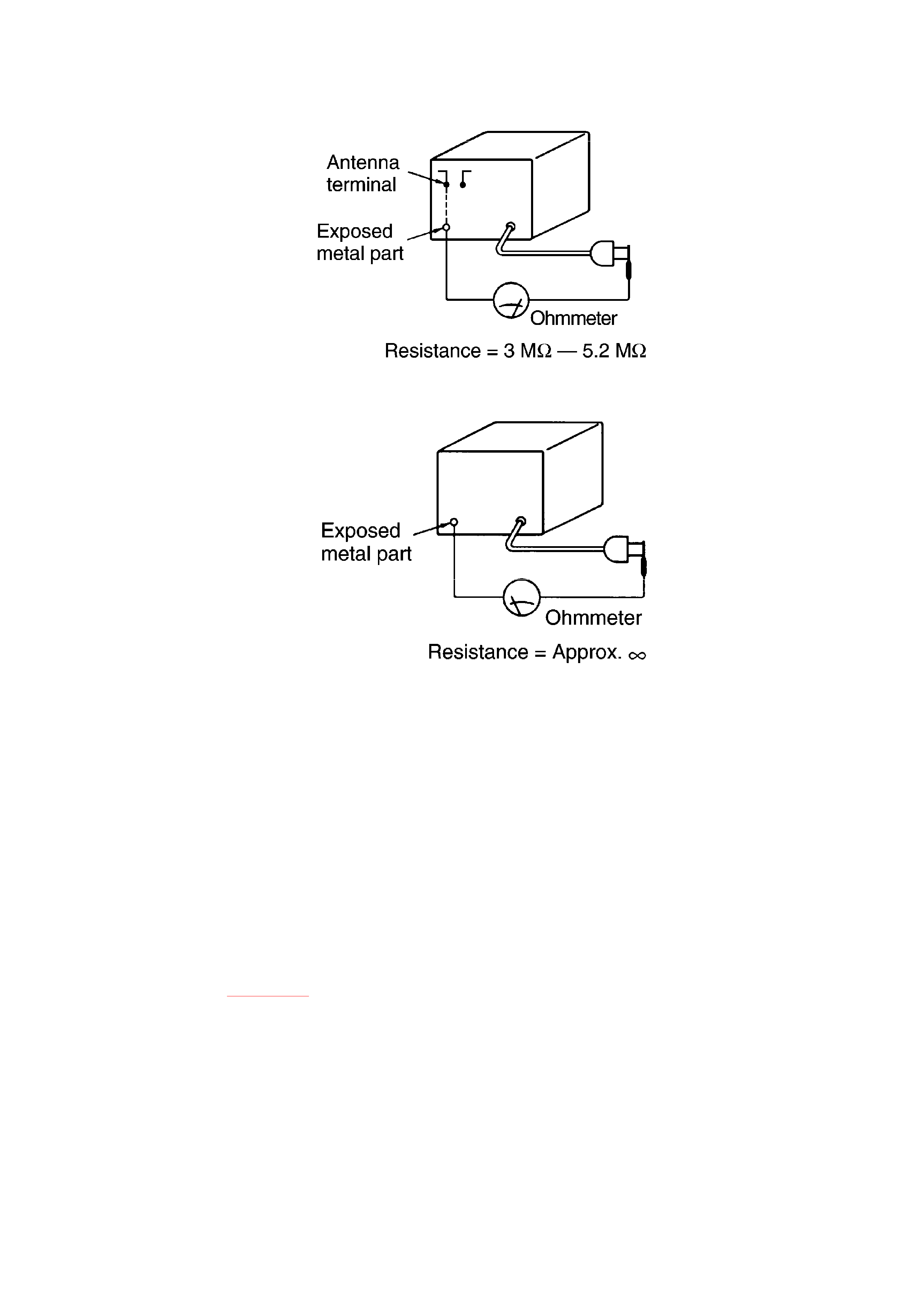
3. Measure the resistance value with ohmmeter between the jumpered
AC plug and each exposed metal cabinet parts, such as screw heads
antenna, control shafts, handle brackets, etc.. Equipment with antenna
terminals should read between 3 M
-5.2 M
to all exposed parts.
Refer to Fig. 1-1. Equipment without antenna terminals should read
approximately infinity to all exposed parts. Refer to Fig. 1-2.
Note:
Some exposed parts may be isolated from the chassis by design.
These will read infinity.
4. If the measurement is outside the specified limits, there is a possibility
of a shock hazard. The equipment should be repaired and rechecked
before it is returned to the customer.
Fig. 1-1.
2

Fig. 1-2.
2. Handling Precautions for Traverse Deck
The laser diode in the traverse deck (optical pickup) may break down due to potential difference
caused by static electricity of clothes or human body.
So be careful of electrostatic breakdown during repair of the traverse deck (optical pickup).
2.1. Handling of traverse deck (optical pickup)
1. Do not subject the traverse deck (optical pickup) to static electricity as
it is extremely sensitive to electrical shock.
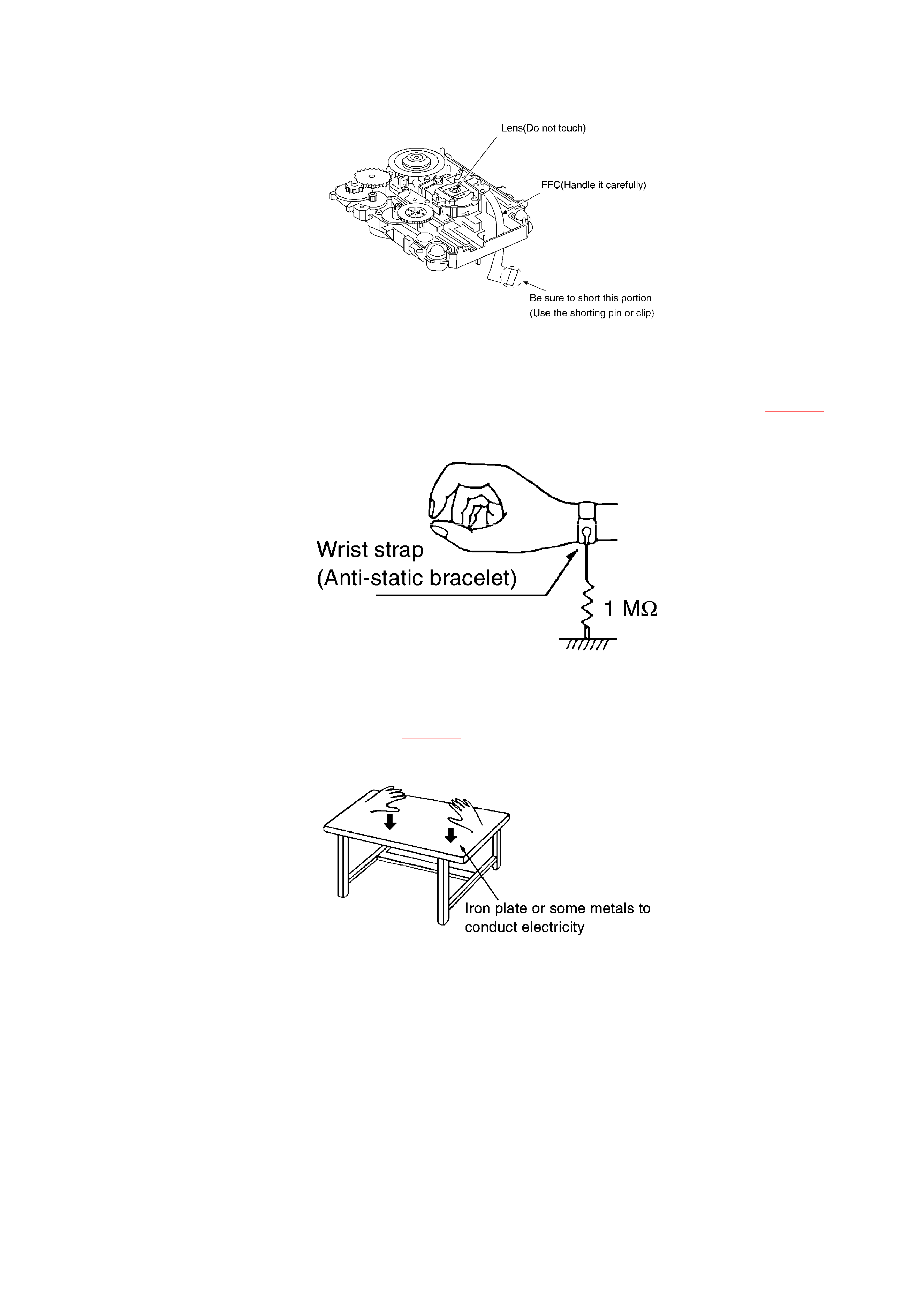
2. To prevent the breakdown of the laser diode, an anti-static shorting
pin is inserted into the flexible board (FFC board). When removing or
connecting the shorting pin, finish the job in as short time as possible.
Refer to Fig. 2-1.
3. Take care not to apply excessive stress to the flexible board (FFC
board).
4. Do not turn the variable resistor (laser power adjustment). It has
already been adjusted.
Fig. 2-1.
3

2.2. Grounding for electrostatic breakdown prevention
2.2.1. Human body grounding
Use the anti-static wrist strap to discharge the static electricity from your body. Refer to Fig. 2-2.
Fig. 2-2.
2.2.2. Work table grounding
Put a conductive material (sheet) or steel sheet on the area where the traverse deck (optical pickup) is
placed, and ground the sheet. Refer to Fig. 2-3.
Fig. 2-3.
Caution:
The static electricity of your clothes will not be grounded through the
wrist strap.
So take care not to let your clothes touch the traverse deck (optical
pickup).
3. Precaution of Laser Diode
Caution:
This unit utilizes a class 1 laser. Invisible laser radiation is emitted from
4

the optical pickup lens when the unit is turn on:
1. Do not look directly into the pickup lens.
2. Do not use optical instruments to look at pickup lens.
3. Do not adjust the preset variable resistor on the optical pickup.
4. Do not disassemble the optical pickup unit.
5. If the optical pickup is replaced, use the manufacture's specified
replacement pickup only.
6. Use of control or adjustment or performance of procedures other than
those specified herein may result in hazardous radiation exposure.
4. Accessories
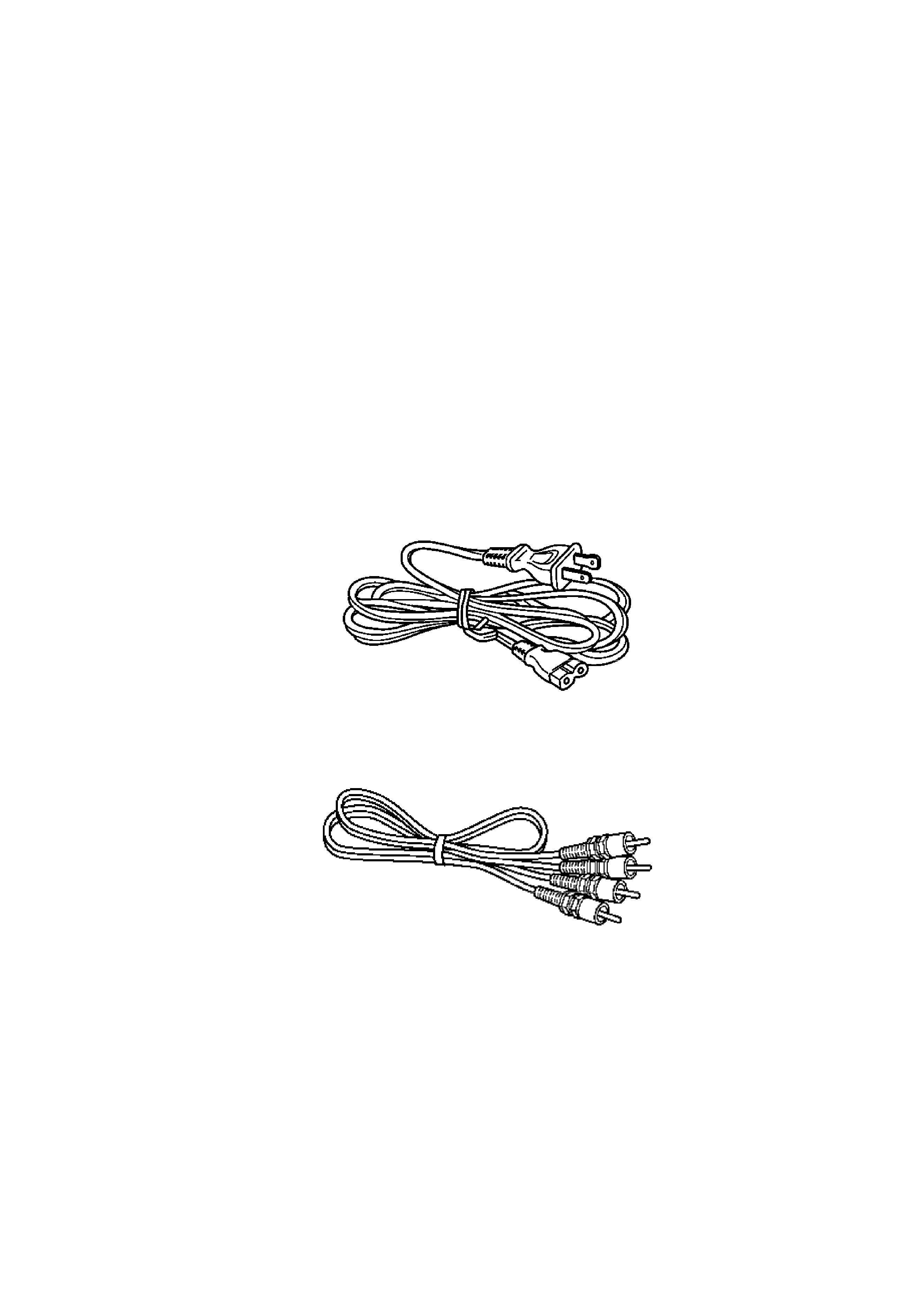
- AC power supply cord
(RJA0065-A).................................................1 pc.
- Stereo connection cable
(RJL2P004B08A)........................................1 pc.
- Remote control
(EUR645275)..............................................1 pc.
5
