AD0002040C2
Sound Processor
SH-EH760
Colour
(S)..........Silver Type
Area
(E)..........Europe.
SPECIFICATIONS
1
2000 Matsushita Electric Industrial Co., Ltd. All rights reserved.
Unauthorized copying and distribution is a violation of law.
1. Note
Refer to the service manual for Model No. SA-EH760 (Order No. AD0002037C2) for information
on Packaging.
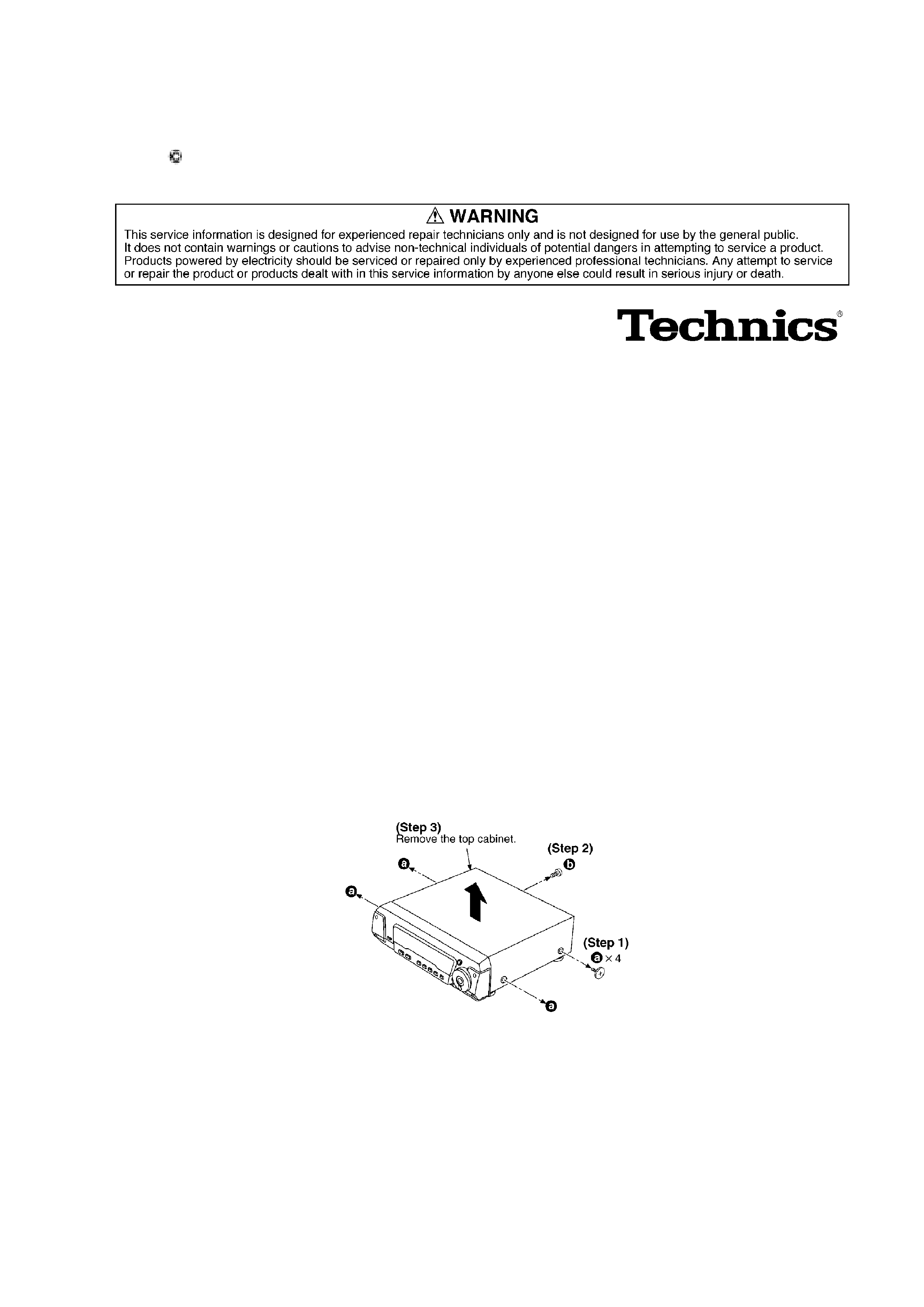
2. Location of Controls
3. Operation Checks and Component Replacement /
Procedures
- This section describes procedures for checking the operation of
the major printed circuit boards and replacing the main
components.
- For reassembly after operation checks or replacement, reverse the
respective procedures. Special reassembly procedures are
described only when required.
/
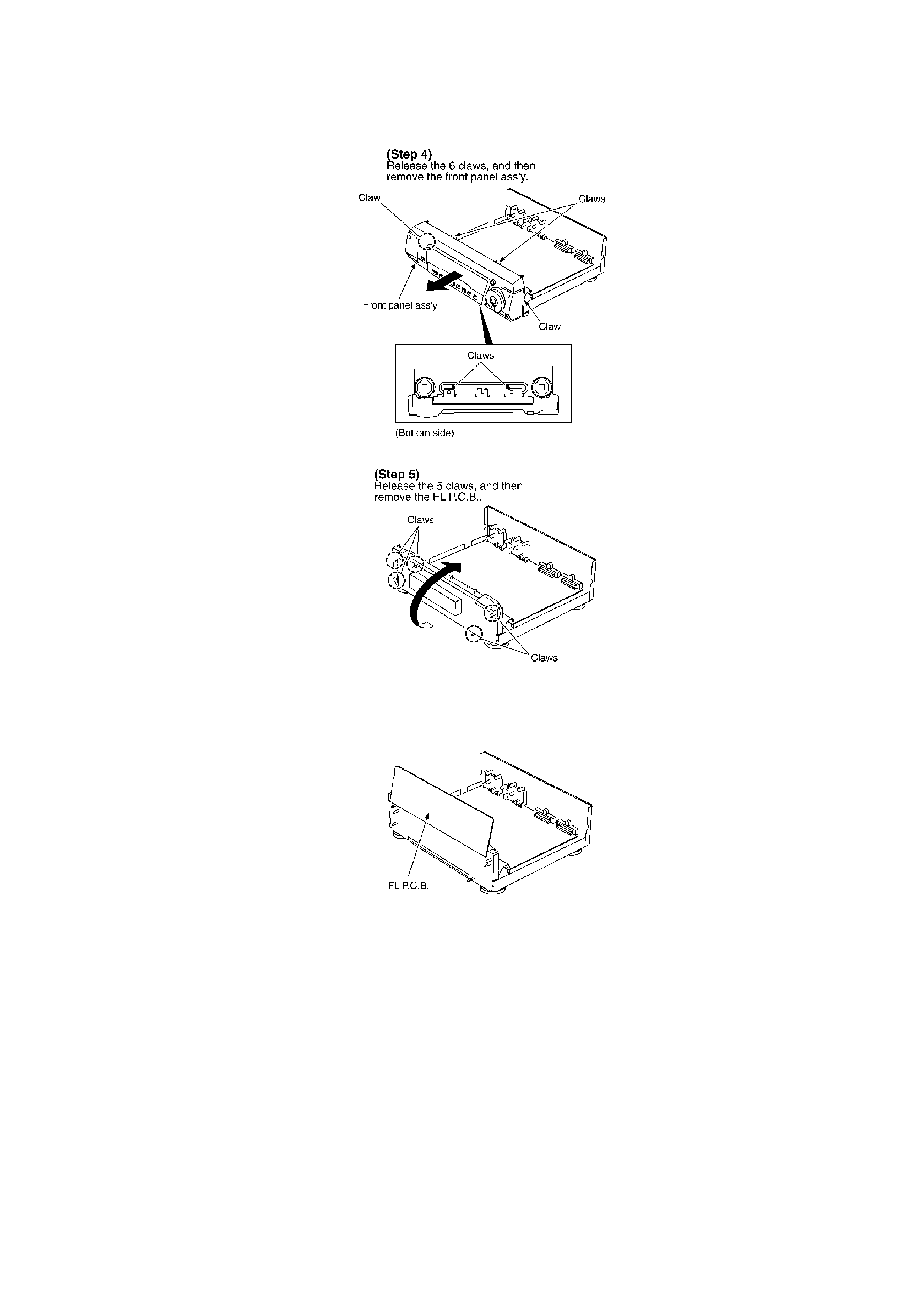
3.1. Checking for the FL P.C.B.
/
/ / /
2
/
- Check the FL P.C.B. as shown below.
/ / /
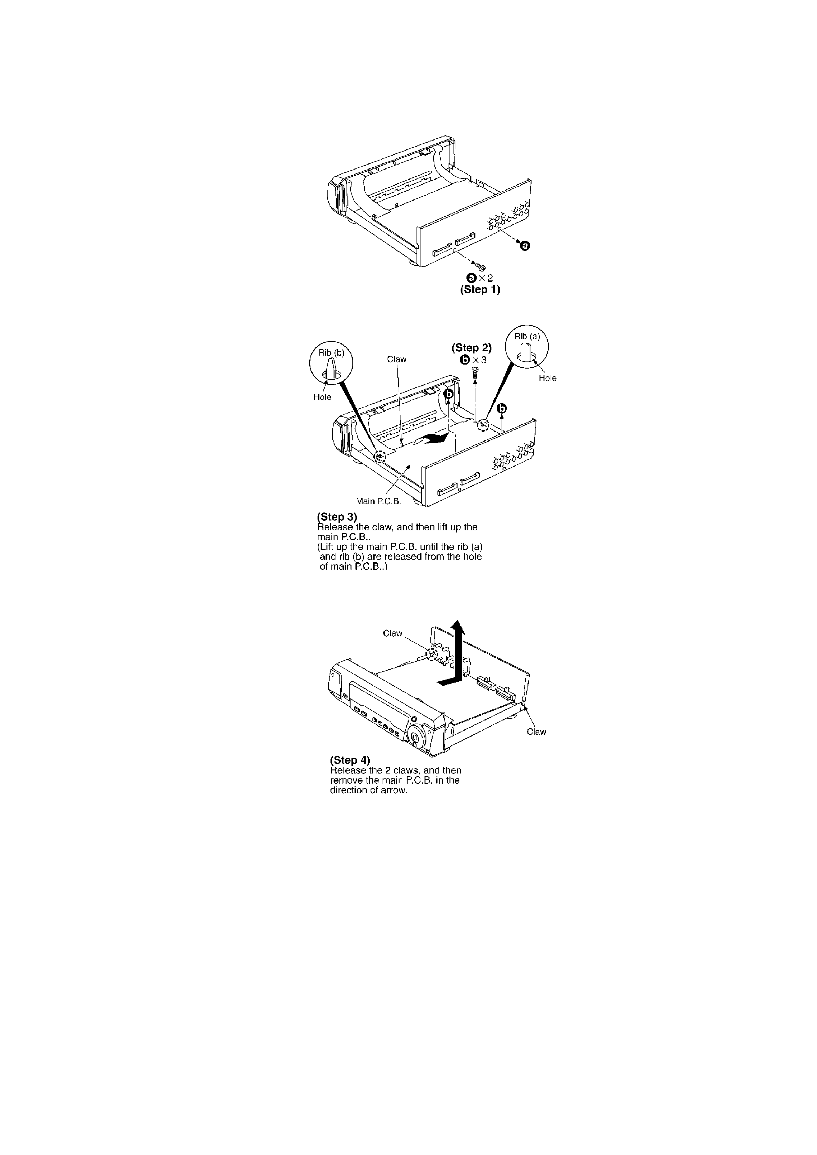
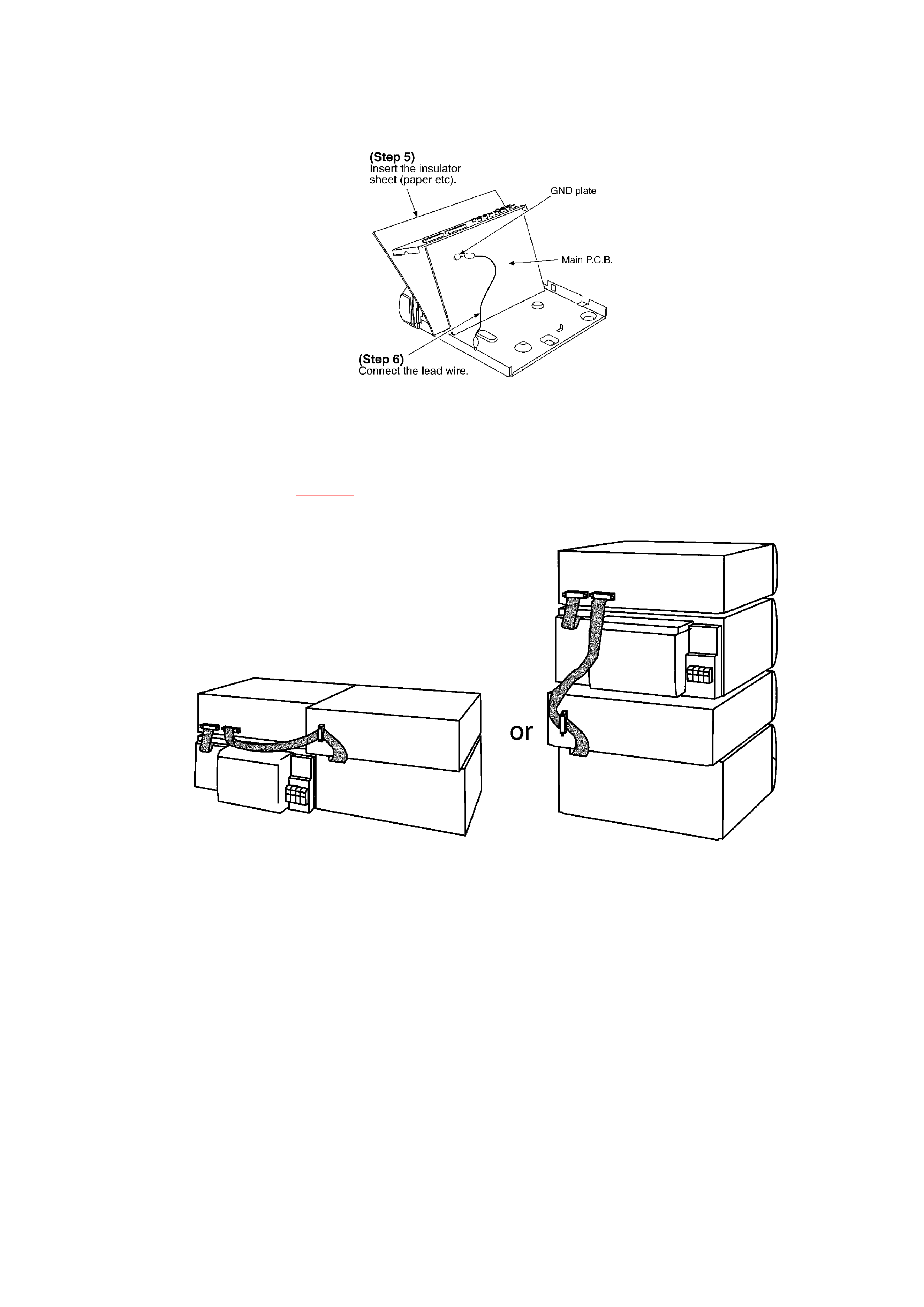
3.2. Checking for the main P.C.B.
- Follow the (Step 1) - (Step 3) of item 3.1.
3
/
/
- Check the main P.C.B. as shown below.
4
4. To Supply Power Source
This unit is designed to operate on power supplied from system connected. / When a
component requires service, use the system connections to supply power source. / For system
connections, refer to Fig. 4-1.
Fig. 4-1.
5. Schematic Diagram Notes
- This schematic diagram may be modified at any time with the
development of new technology.
Notes:
S601:
Display mode switch / (DISPLAY MODE)
S602:
5