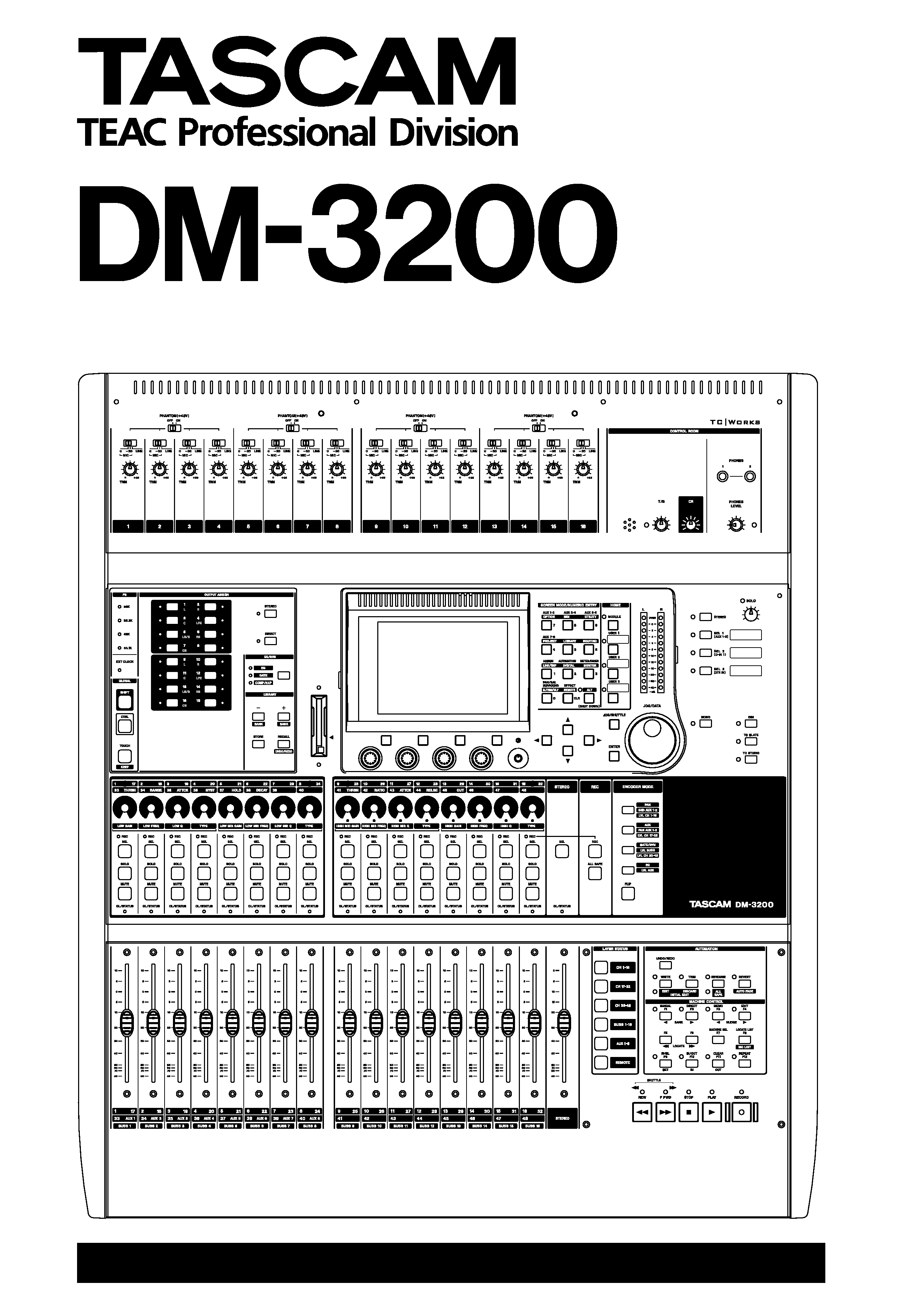
Digital Mixing Console
OWNER'S MANUAL
D001
865710A
2 TASCAM DM-3200 Owner's Manual
IMPORTANT SAFETY PRECAUTIONS
TO THE USER
This equipment has been tested and found to
comply with the limits for a Class A digital device,
pursuant to Part 15 of the FCC Rules. These
limits are designed to provide reasonable
protection against harmful interference when the
equipment
is
operated
in
a
commercial
environment. This equipment generates, uses,
and can radiate radio frequency energy and, if
not installed and used in accordance with the
instruction
manual,
may
cause
harmful
interference to radio communications.
Operation of this equipment in a residental area
is likely to cause harmful interference in which
case the user will be required to correct the
interference at his own expense.
CAUTION
Changes or modifications to this equipment not
expressly approved by TEAC CORPORATION
for compliance could void the user's authority to
operate this equipment.
For the consumers in Europe
WARNING
This is a Class A product. In a domestic environment, this
product may cause radio interference in which case the
user may be required to take adequate measures.
Pour les utilisateurs en Europe
AVERTISSEMENT
Il s'agit d'un produit de Classe A. Dans un environnement
domestique,
cet
appareil
peut
provoquer
des
interférences radio, dans ce cas l'utilisateur peut être
amené à prendre des mesures appropriées.
Für Kunden in Europa
Warnung
Dies is eine Einrichtung, welche die Funk-Entstörung
nach Klasse A besitzt. Diese Einrichtung kann im
Wohnbereich Funkstörungen versursachen ; in diesem
Fall kann vom Betrieber verlang werden, angemessene
Maßnahmen durchzuführen und dafür aufzukommen.
For U.S.A
CAUTION: TO REDUCE THE RISK OF ELECTRIC SHOCK, DO NOT REMOVE
COVER (OR BACK). NO USER-SERVICEABLE PARTS INSIDE. REFER SER-
VICING TO QUALIFIED SERVICE PERSONNEL.
The exclamation point within an equilateral triangle is intended to alert the user to the presence
of important operating and maintenance (servicing) instructions in the literature accompanying
the appliance.
The lightning flash with arrowhead symbol, within an equilateral triangle, is intended to alert the
user to the presence of uninsulated "dangerous voltage" within the product's enclosure that
may be of sufficient magnitude to constitute a risk of electric shock to persons.
This appliance has a serial number
located on the rear panel. Please record
the model number and serial number and
retain them for your records.
Model number
Serial number
Ü
ÿ
Y
WARNING: TO PREVENT FIRE OR SHOCK
HAZARD, DO NOT EXPOSE THIS
APPLIANCE TO RAIN OR MOISTURE.
CE Marking Information
a) Applicable electromagnetic environment: E4
b) Peak inrush current: 8A
TASCAM DM-3200 Owner's Manual
3
IMPORTANT SAFETY INSTRUCTIONS
1
Read these instructions.
2
Keep these instructions.
3
Heed all warnings.
4
Follow all instructions.
5
Do not use this apparatus near water.
6
Clean only with dry cloth.
7
Do not block any ventilation openings. Install in
accordance with the manufacturer's instructions.
8
Do not install near any heat sources such as radi-
ators, heat registers, stoves, or other apparatus
(including amplifiers) that produce heat.
9
Do not defeat the safety purpose of the polarized
or grounding-type plug. A polarized plug has
two blades with one wider than the other.
Grounding type plug has two blades and a third
grounding prong. The wide blade or the third
prong are provided for your safety. If the pro-
vided plug does not fit into your outlet, consult
an electrician for replacement of the obsolete
outlet.
10 Protect the power cord from being walked on or
pinched, particularly at plugs, convenience
receptacles, and the point where they exit from
the apparatus.
11 Only use attachments/accessories specified by
the manufacturer.
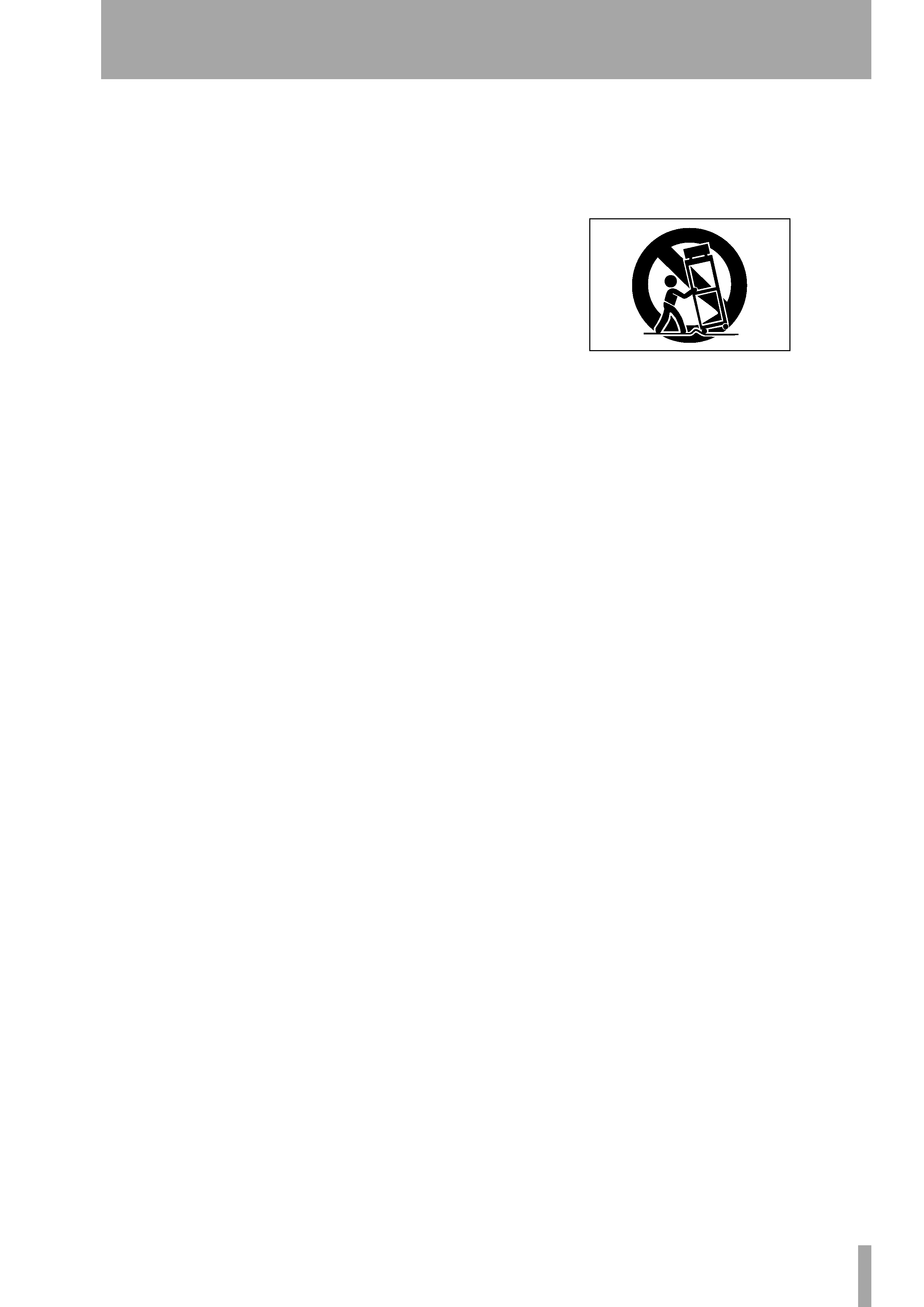
12 Use only with the cart, stand, tripod, bracket, or
table specified by the manufacturer or sold with
the apparatus. When a cart is used, use caution
when moving the cart/apparatus combination to
avoid injury from tip-over.
13 Unplug this apparatus during lightning storms or
when unused for long periods of time.
14 Refer all servicing to qualified service person-
nel. Servicing is required when the apparatus has
been damaged in any way, such as power-supply
cord or plug is damaged, liquid has been spilled
or objects have fallen into the apparatus, the
apparatus has been exposed to rain or moisture,
does not operate normally, or has been dropped.
Do not expose this apparatus to drips or
splashes.
Do not place any objects filled with liquids, such
as vases, on the apparatus.
Do not install this apparatus in a confined space
such as a book case or similar unit.
The apparatus draws nominal non-operating
power from the AC outlet with its POWER
switch in the off position.
The apparatus should be located close enough to
the AC outlet so that you can easily grasp the
power cord plug at any time.
An apparatus with Class I construction shall be
connected to an AC outlet with a protective
grounding connection.

Contents
4 TASCAM DM-3200 Owner's Manual
1 Introduction
Computer (DAW) integration ...................................... 9
Other key points .......................................................... 9
Please read this manual ............................................... 9
About the DM-3200 ....................................... 10
Inputs ....................................................................... 10
Channel modules .................................................... 10
Channel destinations .............................................. 11
Outputs .................................................................... 11
Effects ......................................................................... 11
Unpacking the DM-3200 ............................... 11
About the manual ......................................... 12
What's in the manual ................................................. 12
1, "Introduction" (page 9) ...................................... 12
2, "Basic operational concepts" (page 16) ............. 12
3, "Connections" (page 38) ..................................... 12
4, "Routing & assignment" (page 46) .................... 12
5, "Channel modules" (page 59) ............................ 12
6, "Effects" (page 81) .............................................. 12
7, "MIDI" (page 91) ................................................. 12
8, "Remote operation" (page 93) ........................... 12
9, "Specifications" (page 102) ................................ 12
Notes and warnings ................................................... 12
Special notes for touch-sensitive faders ...... 13
Copyright, etc. ............................................... 13
The features of the DM-3200 ........................ 14
Control section ........................................................... 15
Monitoring section ..................................................... 15
Module & layer control section ................................. 15
Encoder section .......................................................... 15
Modifier section ......................................................... 15
Library section and CF card slot ................................ 15
Machine control section ............................................ 15
Analog input section .................................................. 15
2 Basic operational concepts
Smart keys .................................................................. 16
What's on the screen? ............................................... 16
Jumping to commonly-used screens ......................... 17
Setting a USER screen ............................................. 17
Fader layers ................................................................ 18
Special controls .............................................. 18
The PODs ..................................................................... 18
Encoders ......................................................... 20
Encoder mappings ...................................................... 20
Pan mode ................................................................. 20
Aux mode ................................................................ 20
GATE/DYN dynamics processor mode ................... 20
EQ ............................................................................. 21
SND AUX 12 ........................................................... 21
PAN AUX 12 ........................................................... 21
LVL BUSS .................................................................. 21
LVL AUX ................................................................... 21
LVL CH 116, 1732, 3348 ..................................... 21
Reading the encoder indicators ................................ 21
Pan settings ............................................................. 21
EQ settings .............................................................. 22
Module levels and AUX sends ............................... 23
Dynamics settings ................................................... 23
The FLIP key ............................................................. 23
Encoder behavior ....................................................... 23
CF cards ...........................................................24
Formatting a new card ...............................................24
Shutting down the DM-3200 .........................25
IMPORTANT CAUTION!!! ........................................25
How to shut down the DM-3200 ...........................25
Starting up the DM-3200 ...........................................25
About projects and libraries ..........................26
Setting the date and time ..........................................27
Creating a new project ...............................................27
Using a template .....................................................27
Managing projects ......................................................28
Loading a project .....................................................28
Copying a project ....................................................28
Deleting a project ....................................................28
Renaming a project ........................................ 28
Saving project data ....................................................29
Library management ......................................30
Using library banks .................................................30
Viewing library entries ...........................................31
Recalling library entries ..........................................31
Storing library entries .............................................31
Deleting library entries ...........................................31
Library utilities ............................................................31
Target parameters ...................................................31
Source parameters ..................................................32
Naming library entries ...................................32
Options ...........................................................32
SETUP screen ...............................................................32
UPPER BAR DISPLAY ................................................33
LOCATE DISPLAY mode ...........................................33
ENCODER OPERATION mode ..................................33
LIBRARY DIRECT KEY OPERATION ..........................33
OL/STATUS LED TYPE ..............................................33
FADER SENSITIVITY .................................................33
PREFERENCES ..............................................................34
Fader Auto MODULE Select ....................................34
CH SOLO Key Auto MODULE Select .......................34
Select MODULE Return ...........................................34
ST Link by SEL key ...................................................34
SEL Key Follows Fader Layer Status .......................34
Meter Follows SEL key ............................................34
Automation fader OFF ............................................34
Balance Level CENTER:0dB ......................................34
AUX Mute follows CH Mute ...................................34
Encoder Mode Follows Current Screen ..................34
Current Screen Follows Encoder Mode ..................34
BUSS PAN Follows ST PAN ......................................34
BUSS Link/BUSS PAN are Linked ............................35
SOLO ..........................................................................35
MODE SELECT ..........................................................35
SOLO LINK ................................................................35
SOLO TYPE ...............................................................35
INPLACE SOLO DEFEAT ...........................................35
Utilities ............................................................36
UTILITY copying ..........................................................36
SWITCH utility .............................................................37
Talkback ...................................................................37
Machine Control ......................................................37
Other functions .......................................................37
Polarity .....................................................................37

Contents
TASCAM DM-3200 Owner's Manual
5
3 Connections
Analog connections ........................................39
Mic/line connections .................................................. 39
Channel inserts ........................................................39
2 TR IN ......................................................................39
ASSIGNABLE RETURNS ............................................39
Analog outputs ...........................................................40
STEREO OUT ............................................................40
ASSIGNABLE SENDS ................................................ 40
Monitoring (CR OUTPUTS) ......................................40
Monitoring (STUDIO OUTPUTS) .............................40
Digital connections .........................................40
Digital audio I/O .........................................................40
TDIF I/O ....................................................................40
ADAT "lightpipe" OUT & IN ....................................40
CASCADE ..................................................................40
Digital inputs and outputs .....................................40
Digital I/O setup .........................................................41
Digital inputs ...........................................................41
Mute Defeat ............................................................41
Stereo output ..........................................................41
Slot card configuration ..............................................42
IF-AN/DM .................................................................42
IF-AE/DM ..................................................................42
IF-TD/DM ..................................................................42
IF AD/DM .................................................................42
Other connections ..........................................42
MIDI connections (IN, OUT and THRU) ..................42
RS-422 serial control terminal ................................42
TIME CODE ...............................................................42
WORD SYNC (IN and OUT/THRU) ...........................42
TO METER ................................................................43
FOOT SW ..................................................................43
USB ...........................................................................43
Power input .............................................................43
Clock setting ...................................................44
Fs MODE ................................................................... 44
Checking the clock .................................................. 44
Varispeed clocking .................................................. 44
Clock change action ................................................ 44
Changing the clock .................................................. 45
Clock phase ..............................................................45
OUT SPEED ...............................................................45
4 Routing & assignment
Routing ............................................................47
Input routing ..............................................................47
Batch routing ...........................................................48
Flipping the channels ..............................................48
Loopback options ....................................................48
Digital input selection .............................................48
Output routing ...........................................................49
Slot card outputs .....................................................49
Insert patching ............................................................50
Send/return linking .................................................50
Channel-to-buss assignment .........................51
Assignment using the front panel ............................51
Using the assignment screens ................................51
Pan switch ................................................................52
Surround assignments ............................................53
Non-channel assignments ......................................53
Bulk assignment ......................................................53
Buss panning ...........................................................53
Monitoring ..................................................... 54
Selecting the CR source ..............................................54
Studio cue source .......................................................55
Talkback, etc. ..............................................................56
Talkback source .......................................................56
Slate definition ........................................................56
Oscillator and noise generator ..................................56
Oscillator destination ..............................................56
Meters .........................................................................57
Meter ballistics .........................................................57
On-screen meter selection ......................................57
Metering points .......................................................57
Soloing ........................................................................58
5 Channel modules
General principles .......................................................59
ASSIGN PARAMETERS screen ..................................59
Global module settings ................................. 60
Input and return display .........................................60
EQ display and button ............................................60
GATE display and button ........................................60
COMP/EXP display and COMP button ....................60
Compressor/expander point button ......................60
Meters and pick-off point button ..........................60
Fader .........................................................................60
MUTE button ............................................................60
PAN (BALANCE) control ...........................................60
PAN follow button ..................................................60
INSERT button ..........................................................60
Phase button ............................................................60
AUX1-2 button .........................................................61
STEREO button .........................................................61
Group assignment displays .....................................61
Fader control ...............................................................61
Master screen ...........................................................61
Dynamics processors ...................................... 62
LINK ..........................................................................62
Trigger mode (
TRG MOD) .......................................62
Trigger selection ......................................................62
Turning the processors on and off .........................62
Gates (input channels 132) .......................................63
GATE .........................................................................63
Threshold (
THRESH) .................................................63
Range (
RANGE) ........................................................63
Gate attack time ......................................................63
Hysteresis (
HYST) .....................................................63
Gate hold time (
HOLD) ............................................63
Gate decay time (DECAY) ........................................63
Compressor/expanders ..............................................63
COMP/EXPAND ........................................................63
Insert point (
INS PNT) .............................................63
Threshold .................................................................63
Compression/expansion ratio .................................63
Attack time ...............................................................63
Release time .............................................................63
Auto make-up ..........................................................64
Output gain ..............................................................64
Library jump buttons ...............................................64
Preset dynamics library entries .................................64
Compressor/expander library entries ....................64
Gate library entries ..................................................65
Trigger settings ...........................................................65
