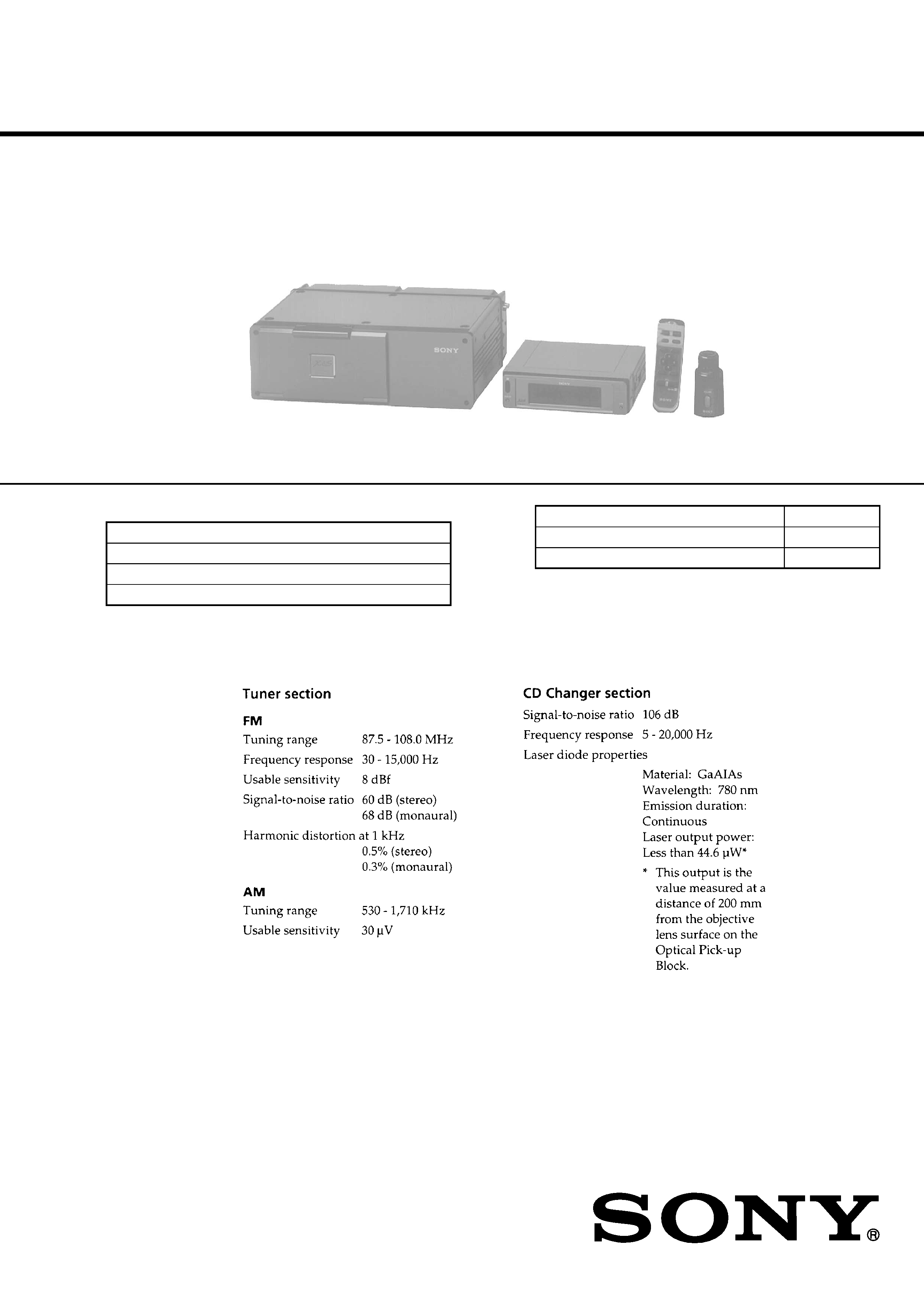
XES-Z50
DIGITAL REFERENCE SOUND SYSTEM
SERVICE MANUAL
Model Name Using Similar Mechanism
NEW
CD Mechanism Type
MG-110ES-132
Optical Pick-up Name
KSS-400A
CHANGER UNIT
CONTROL UNIT
WIRELESS REMOTE COMMANDER (RM-X67)
ROTARY REMOTE COMMANDER (RM-X66)
· This set consists of the following units.
SPECIFICATIONS
Continued on next page
US Model
Canadian Model
9-925-509-12
Sony Corporation
2001I0500-1
e Vehicle Company
C
2001.9
Shinagawa Tec Service Manual Production Group
Ver 1.1 2001.09
2
Flexible Circuit Board Repairing
· Keep the temperature of the soldering iron around 270 °C dur-
ing repairing.
· Do not touch the soldering iron on the same conductor of the
circuit board (within 3 times).
· Be careful not to apply force on the conductor when soldering
or unsoldering.
Notes on chip component replacement
· Never reuse a disconnected chip component.
· Notice that the minus side of a tantalum capacitor may be dam-
aged by heat.
The laser diode in the optical pick-up block may suffer electro-
static breakdown because of the potential difference generated by
the charged electrostatic load, etc. on clothing and the human body.
During repair, pay attention to electrostatic breakdown and also
use the procedure in the printed matter which is included in the
repair parts.
The flexible board is easily damaged and should be handled with
care.
NOTES ON HANDLING THE OPTICAL PICK-
UP BLOCK OR BASE UNIT
Laser Diode Properites
· Material: GaAlAs
· Wavelength: 780 nm
· Emission Duration: continuous
· Laser Output Power: less than 44.6 µW*
* This output is the value measured at a distance of 200 mm
from the objective lens surface on the Optical Pick-up Block.
CAUTION
Use of controls or adjustments or performance of
procedures other than those specified herein may
result in hazardous radiation exposure.
SAFETY-RELATED COMPONENT WARNING!!
COMPONENTS IDENTIFIED BY MARK
! OR DOTTED
LINE WITH MARK
! ON THE SCHEMATIC DIAGRAMS
AND IN THE PARTS LIST ARE CRITICAL TO SAFE
OPERATION. REPLACE THESE COMPONENTS WITH
SONY PARTS WHOSE PART NUMBERS APPEAR AS
SHOWN IN THIS MANUAL OR IN SUPPLEMENTS PUB-
LISHED BY SONY.
ATTENTION AU COMPOSANT AYANT RAPPORT
À LA SÉCURITÉ!
LES COMPOSANTS IDENTIFIÉS PAR UNE MARQUE
!
SUR LES DIAGRAMMES SCHÉMATIQUES ET LA LISTE
DES PIÈCES SONT CRITIQUES POUR LA SÉCURITÉ
DE FONCTIONNEMENT. NE REMPLACER CES COM-
POSANTS QUE PAR DES PIÈCES SONY DONT LES
NUMÉROS SONT DONNÉS DANS CE MANUEL OU
DANS LES SUPPLÉMENTS PUBLIÉS PAR SONY.

3
TABLE OF CONTENTS
1.
SERVICING NOTES
1-1.
Connection at Repair ....................................................
4
1-2.
Front Panel Setting .......................................................
4
1-3.
Removal of Front Panel at Power Off ...........................
4
2.
GENERAL
Overview ......................................................................
5
Precautions ...................................................................
5
Initial Settings ...............................................................
6
Attaching/Detaching the Electrically
Operated Display Section .............................................
7
Setting the Clock ..........................................................
8
Inserting CDs ................................................................
9
Using the Rotary Remote .............................................
11
Using the Wireless Remote ..........................................
12
Menu Display/Lists ......................................................
13
Listening to a CD ..........................................................
13
Playing Tracks Repeatedly ...........................................
14
Playing Tracks in Random Order .................................
15
Selecting Specific Tracks for Playback ........................
15
Setting Sound Effects for Each CD/MD .......................
16
Labeling a CD ...............................................................
17
Locating a Disc by Title ...............................................
18
Viewing CD TEXT Information ...................................
19
Listening to Radio ........................................................
20
Presetting Radio Stations ..............................................
21
Specifying Monaural/Stereo Mode ...............................
22
Receiving Only the Strongest Signals ..........................
23
Labeling Radio Stations ...............................................
23
Selecting a Station by Name .........................................
25
Set up Menu ..................................................................
25
AUX Menu ...................................................................
26
Selecting the Parametric Equalizer Pattern ..................
27
Selecting the Cross-over Network Pattern ...................
28
Listening to an Optional CD/MD Changer ..................
28
Precautions and Maintenance .......................................
29
An Example of FIR Filter
(4095 tap) Frequency Response Table ..........................
30
Installing the Wireless Remote .....................................
31
After Installation and Connections
Have Been Completed ..................................................
31
Installing the Rotary Remote ........................................
31
Installing the Control Unit ............................................
32
Installing the CD Changer ............................................
34
Connection Diagram (3Way System) ...........................
35
System Configuration Examples ..................................
36
3.
DISASSEMBLY .......................................................
37
4.
MECHANICAL ADJUSTMENT .........................
45
5.
TEST MODE ............................................................
46
6.
ELECTRICAL ADJUSTMENTS
Tuner Section ................................................................
46
CD Section ....................................................................
48
Display Section .............................................................
49
7.
DIAGRAMS
7-1.
IC Pin Function Description .........................................
52
7-2.
IC201 (BA6247FP-Y) Motor Driver IC Operation ......
76
7-3.
Block Diagram
-- Control Unit (TUNER Section) -- ..........................
77
7-4.
Block Diagram
-- Control Unit (DISPLAY Section) -- .......................
79
7-5.
Block Diagram -- Control Unit
(BUS CONTROL/POWER SUPPLY Section) -- ........
81
7-6.
Block Diagram
-- Changer Unit (CD Section (1/2)) -- .......................
83
7-7.
Block Diagram
-- Changer Unit (CD Section (2/2)) -- .......................
85
7-8.
Block Diagram
-- Changer Unit (MAIN Section (1/2)) -- ..................
87
7-9.
Block Diagram
-- Changer Unit (MAIN Section (2/2)) -- ..................
89
7-10. Block Diagram
-- Changer Unit (D/A CONVERTER Section) -- ......
91
7-11. Block Diagram -- Changer Unit
(BUS CONTROL/POWER SUPPLY Section) -- ........
93
7-12. Printed Wiring Board
-- Control Unit (MAIN Section) -- ............................
98
7-13. Schematic Diagram
-- Control Unit (MAIN Section) -- ............................ 101
7-14. Schematic Diagram -- Control Unit (FRONT PANEL/
DESORPTION MECHANISM Section) -- ................ 106
7-15. Printed Wiring Boards -- Control Unit (FRONT PANEL/
DESORPTION MECHANISM Section) -- ................ 111
7-16. Printed Wiring Boards
-- Changer Unit (DRIVER Section) -- ....................... 116
7-17. Schematic Diagram
-- Changer Unit (DRIVER Section) -- ....................... 119
7-18. Printed Wiring Boards
-- Changer Unit (CHANGER Section) -- .................. 123
7-19. Schematic Diagram
-- Changer Unit (CHANGER Section) -- .................. 127
7-20. Schematic Diagram
-- Changer Unit (DSP Section) -- .............................. 132
7-21. Printed Wiring Board
-- Changer Unit (DSP Section) -- .............................. 137
7-22. Printed Wiring Boards
-- Changer Unit (DAC Section) -- .............................. 142
7-23. Schematic Diagram
-- Changer Unit (DAC Section) -- .............................. 145
8.
EXPLODED VIEWS .............................................. 170
9.
ELECTRICAL PARTS LIST ............................... 183
4
SECTION 1
SERVICING NOTES
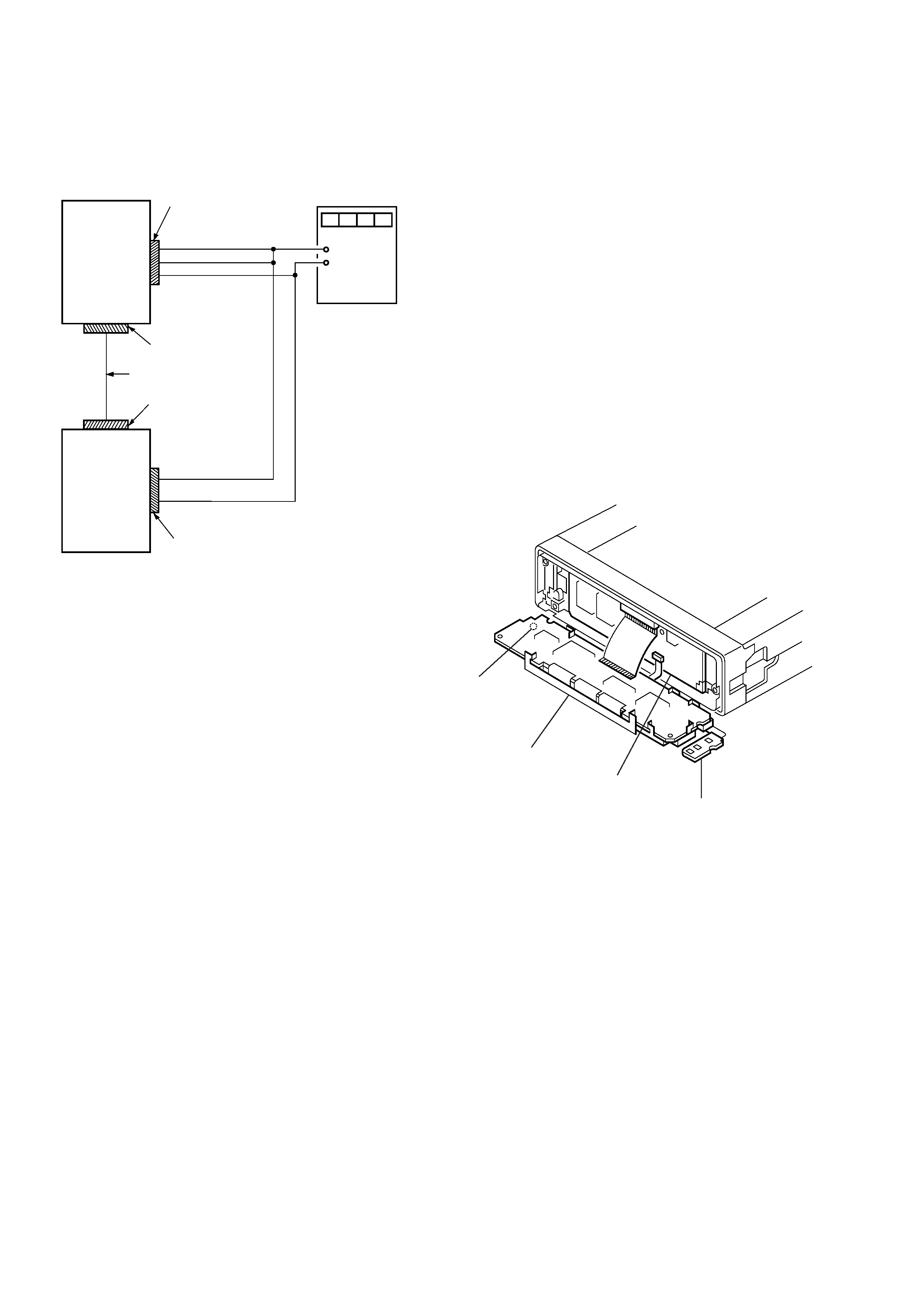
1-1.
CONNECTION AT REPAIR
In repairing this set, connect as follows.
1-2.
FRONT PANEL SETTING
In repairing the front panel, make a setting through the procedure
give below.
Notes:
1. A flat cable and a switch flexible board connected between
liquid crystal module and display board are easily broken, thus
requiring extreme care when handling.
2. As only the removal procedure is given here, see "3. DISAS-
SEMBLY" for details.
Setting:
1. Remove the front panel from control unit.
2. Remove the front panel (ornament) assembly. At this time,
take care not to break the switch flexible board connected to
the display board.
3. Remove the switch flexible board from front panel (ornament)
assembly.
4. Under this condition, attach the front panel to the control unit,
and supply the power.
5. After completion of attachment, turn the power OFF once, and
tilt the liquid crystal module toward the front as shown below.
CONTROL
UNIT
CHANGER
UNIT
CN501
power supply
connector
ACC
BATT
GND
CN502
bus connector
bus cable
CN12
MASTER BUS
CONTROL
connector
CN11
POWER terminal
+12V
GND
regulated dc
power supply
14.4 V dc
+
CONTROL UNIT
RELEASE
button
liquid crystal
module
DISPLAY board
SWITCH FLEXIBLE board
1-3.
REMOVAL OF FRONT PANEL AT POWER OFF
Refer to "3. DISASSEMBLY" (page 42).
5
SECTION 2
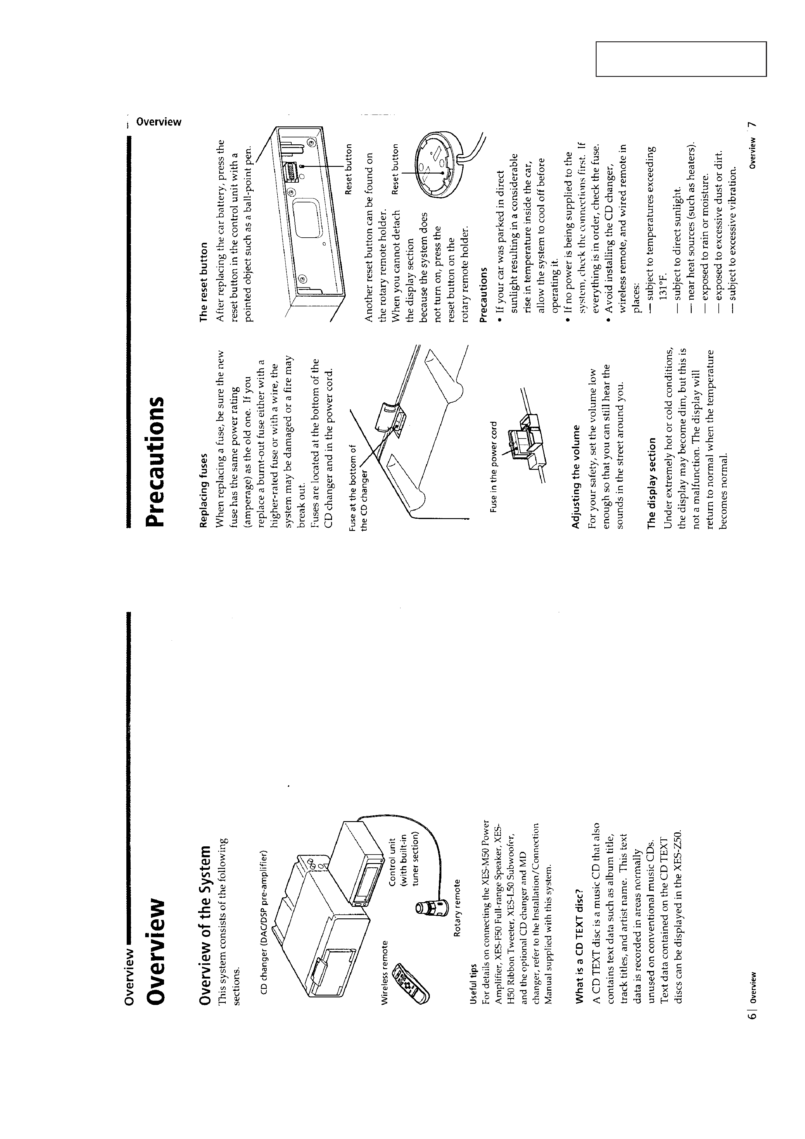
GENERAL
This section is extracted from
instruction manual.
