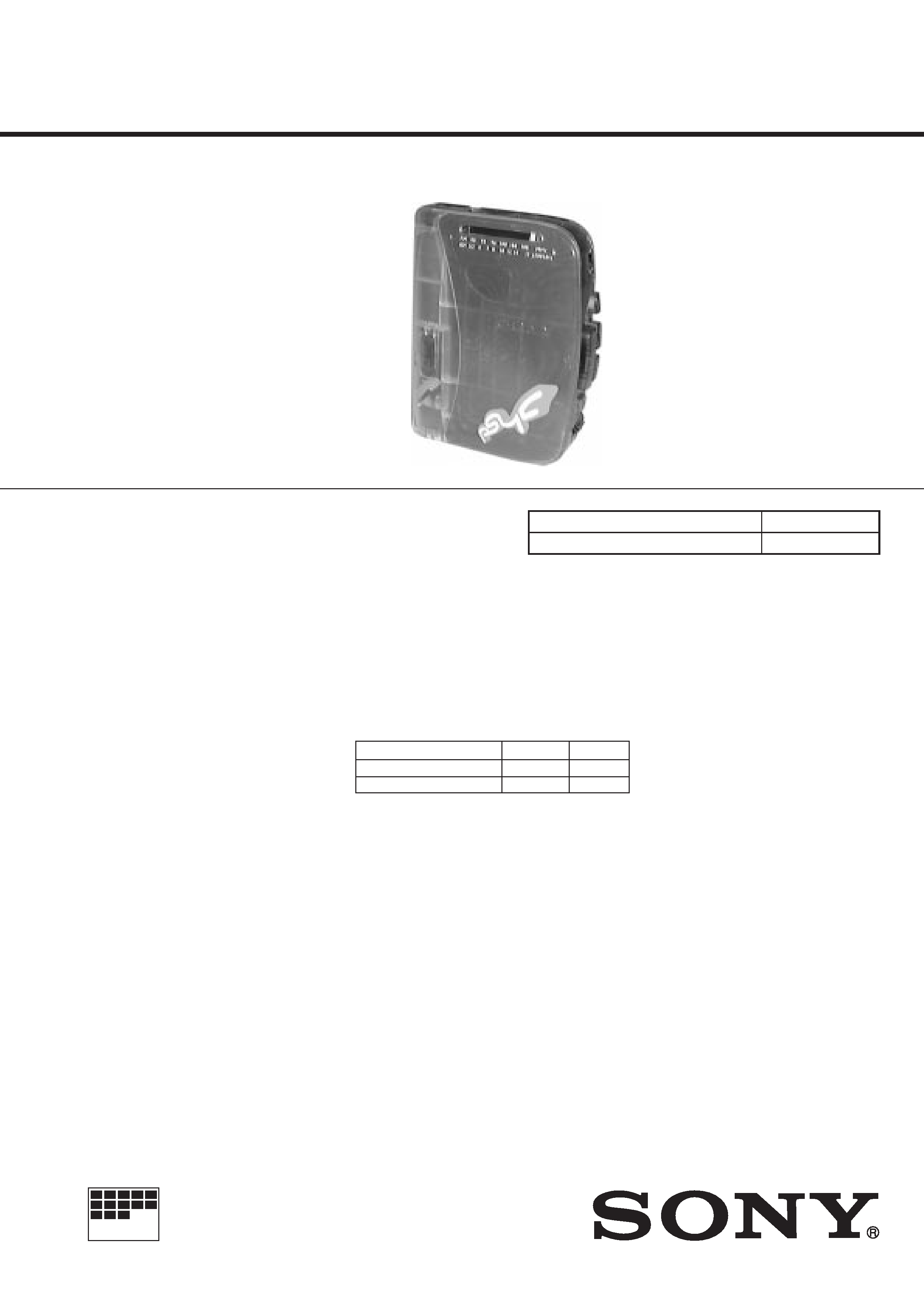
WM-PSY01
US Model
Canadian Model
SERVICE MANUAL
RADIO CASSETTE PLAYER
MICROFILM
Model Name Using Similar Mechanism
WM-FX323
Tape Transport Mechanism Type
MF-WMFX305-43
SPECIFICATIONS
Radio Frequency
FM : 87.6 108 MHz
AM : 530 1,710 kHz
Power Requirements
3 V DC Batteries AA (R6)
× 2
External DC 3 V power sources
Battery Life
(EIAJ*)
(approximate hours when using the batteries specified below)
* Measured value by the standard of EIAJ(Electronic Industries Association of
Japan). (Using a Sony HF series cassette tape)
Dimensions
118.8
× 89.5 × 34.1 mm(4 3/
4
× 3 5/
8
× 1 3/
8
in)
(w/h/d) incl. projecting parts
Mass
205 g (7.3 oz) incl. batteries
Supplied Accessories
· Stereo headphones or stereo earphones (1)
· Belt clip (1)
· Bumper guard (1)
· Chain (1)
Use of chain may cause scratching of the unit in nomal use.
Design and specifications are subject to change without notice.
Battery
Playback
Radio
Sony Alkaline LR6 (SG)
16 hours
48 hours
Sony R6P (SR)
4.5 hours
16 hours
Ver 1.1 1999. 04
With SUPPLEMENT (9-926-947-81)
-- 2 --
TABLE OF CONTENTS
Notes on chip component replacement
· Never reuse a disconnected chip component.
· Notice that the minus side of a tantalum capacitor may be
damaged by heat.
Flexible Circuit Board Repairing
· Keep the temperature of soldering iron around 270°C
during repairing.
· Do not touch the soldering iron on the same conductor of the
circuit board (within 3 times).
· Be careful not to apply force on the conductor when soldering
or unsoldering.
SECTION 1
GENERAL
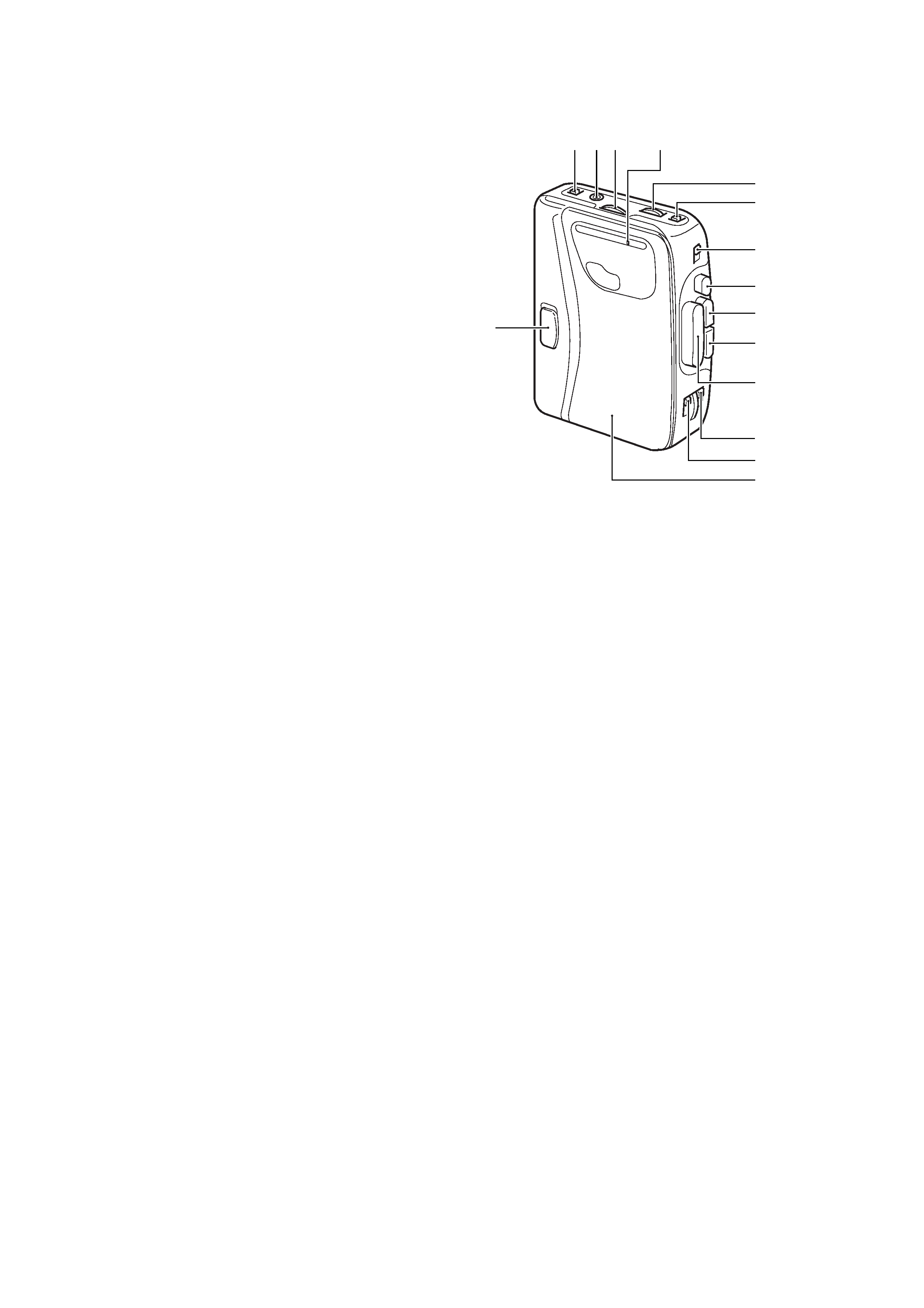
1
AVLS switch
2
2 jack
3
TUNING knob
4
DIAL pointer
5
VOLUME knob
6
NORM-CrO2/METAL switch
7
FM/AM/TAPE(RADIO OFF) switch
8
p STOP button
9
0 button
0
) button
!¡
9 PLAY button
!TM
MODE switch
!£
9( switch
!¢
CASSETE holder
!
MEGA BASS switch
1. GENERAL ·········································································· 2
2. DISASSEMBLY
2-1.
Cabinet (rear) ······································································ 3
2-2.
Cabinet (front) ···································································· 3
2-3.
Main Board ········································································· 4
2-4.
Cassette Lid ········································································ 4
2-5.
Mega Bass Unit ·································································· 5
2-6.
Note For Installation
· Dial Pointer ······································································ 5
· Torsion Spring ·································································· 5
3. MECHANICAL ADJUSTMENT ·································· 6
4. ELECTRICAL ADJUSTMENT ···································· 6
5. DIAGRAMS
5-1.
Block Diagram ··································································· 9
5-2.
IC Block Diagrams ··························································· 11
5-3.
Printed Wiring Board ························································ 13
5-4.
Schematic Diagram ·························································· 17
6. EXPLODED VIEWS ················································· 20
7. ELECTRICAL PARTS LIST ··································· 23
123
4
5
6
7
8
9
0
!¡
!TM
!£
!¢
!
-- 3 --
SECTION 2
DISASSEMBLY
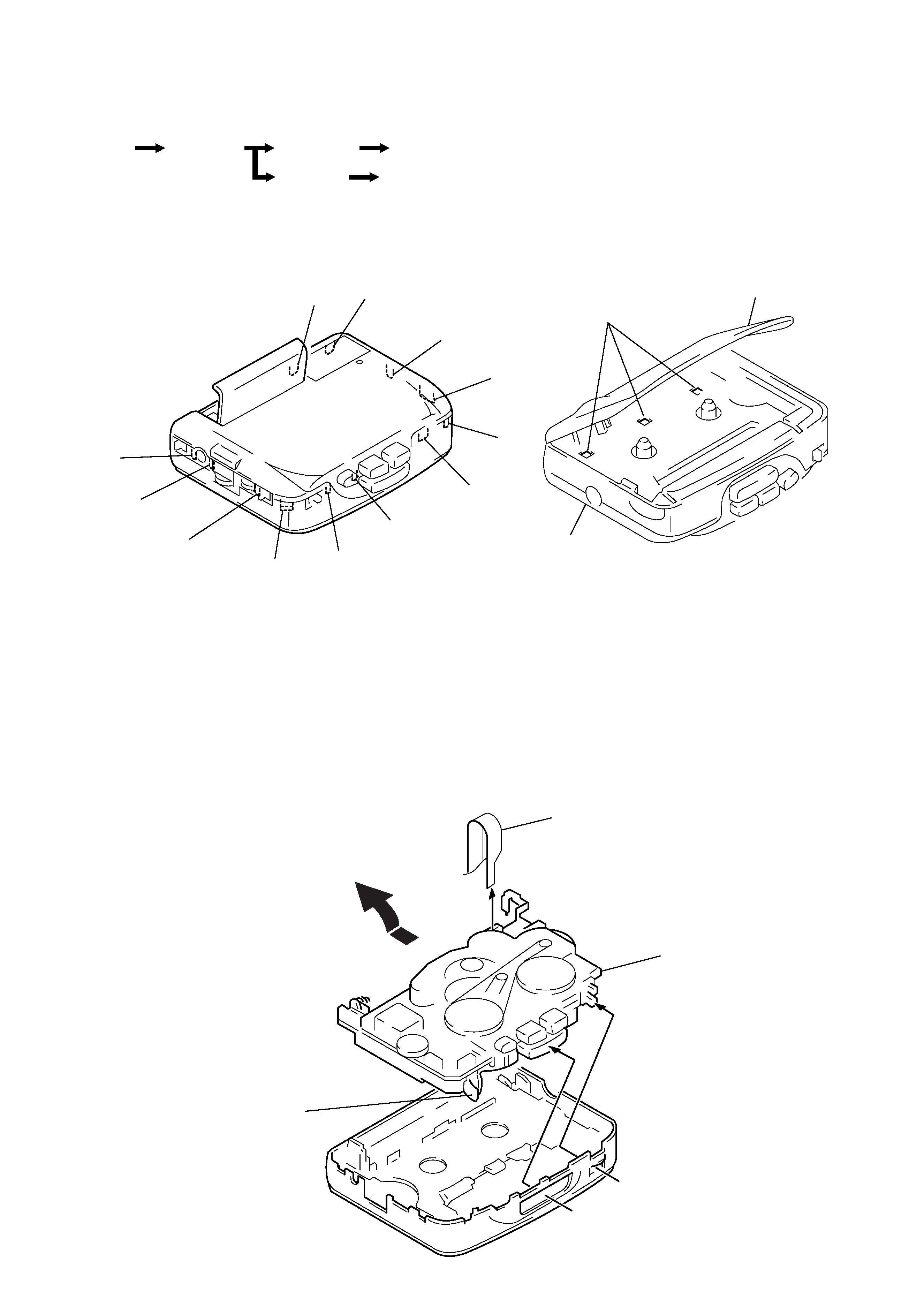
Note :
Follow the disassembly procedure in the numerical order given.
Note :
Disassemble the unit in the order as shown below.
2-1. CABINET (REAR)
2-2. CABINET (FRONT)
B
C
D
E
I
L
M
K
J
H
G
F
Cassette lid
Cabinet(rear)
1 Open the cassette lid and release claw A.
2 Remove the cabinet(rear).(Release
all claws B from M in alphabetical order.)
A
1 Flexible board
2 Remove the mechanism deck
and main board in the
direction of the arrow.
Mechanism deck and
MAIN board
* Note for installation:
Make sure to put the head flexible
board to ditch before install the
mechanism deck and MAIN board.
*
Head flexible board
Set
Cabinet(rear)
Cabinet(front)
Main board
Cassette lid
Mega bass unit
-- 4 --
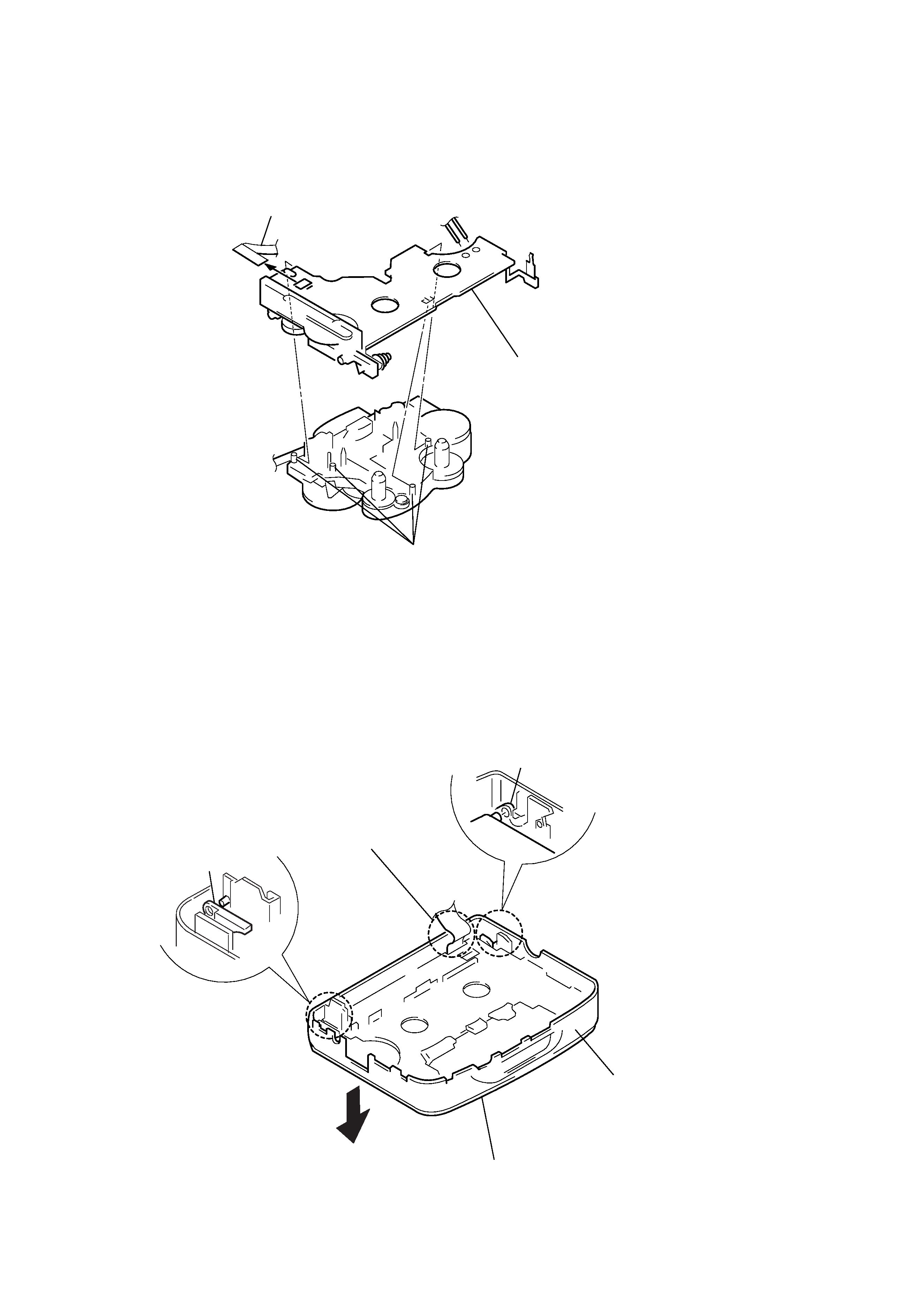
2-3. MAIN BOARD
2-4. CASSETTE LID
2 Remove the solder of the
motor wire.
4 Main board
1 Head flexible board
3 Claws
Front cabinet
A
3 Cassette lid
(Remove it in the
direction of the arrow)
1 Release the catch A.
2 Release the catch B.
B
Note: When the Cassette lid is
installed to the unit, Pass
the flexible board through
a square hole.
-- 5 --
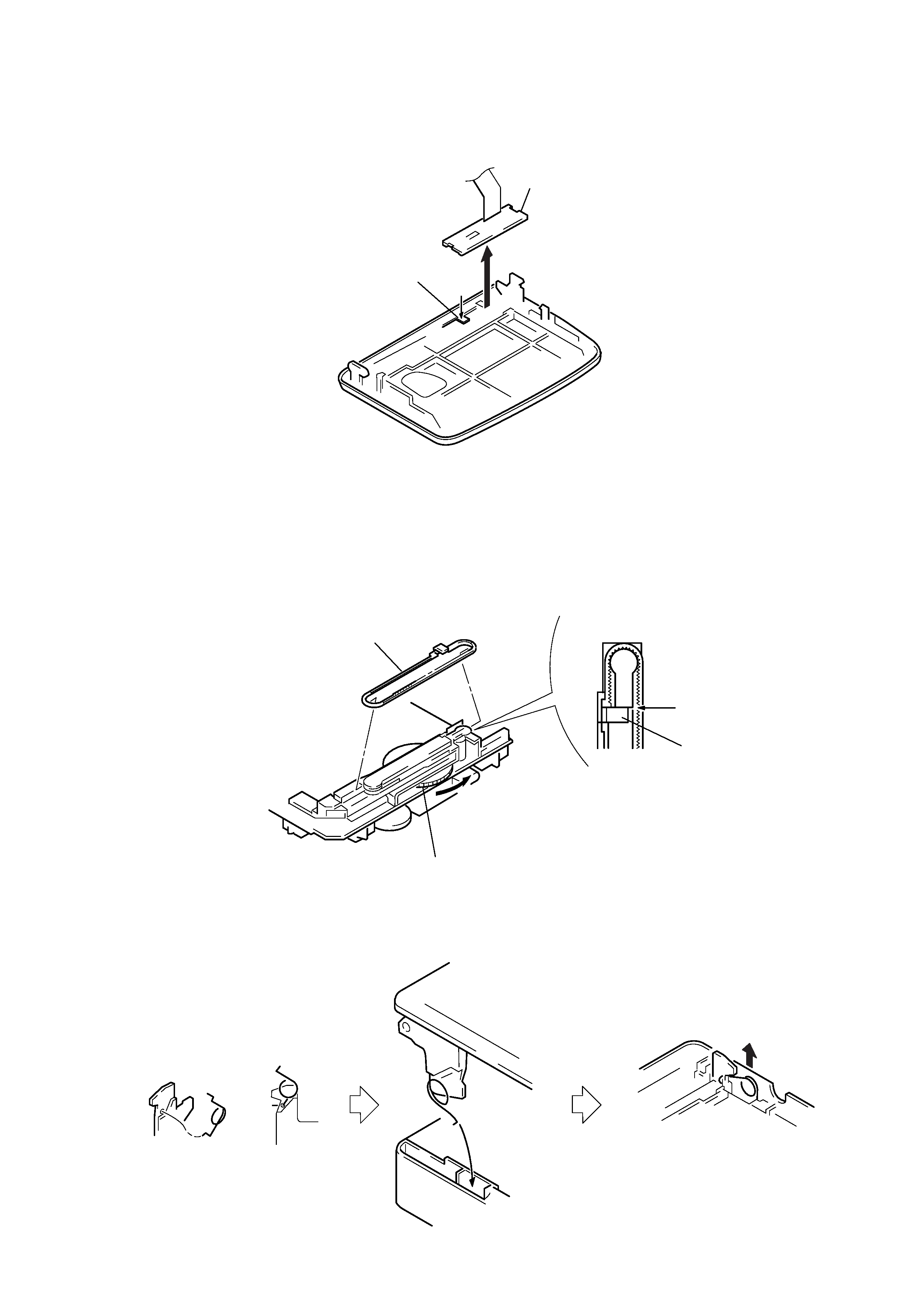
2-5. MEGA BASS UNIT
2-6. NOTE FOR INSTALLATION
· DIAL POINTER
2 Remove the mega bass
unit in the derection of
the arrow.
1 Claw
2 Align pointer with arrow
marked side as shown in Fig.1
and then fit to groove in the
order of A and B.
Align
Pointer
Fig. 1
Pointer
1 Rotate tune knob fully to arrow direction.
A
B
·TORSION SPRING
1 Attach the torsion spring as
shown in the figure.
2 Insert the torsion spring in the hole as
shown in the figure.
3 Lift the torsion spring in the arrow direction and
hook it properly.
