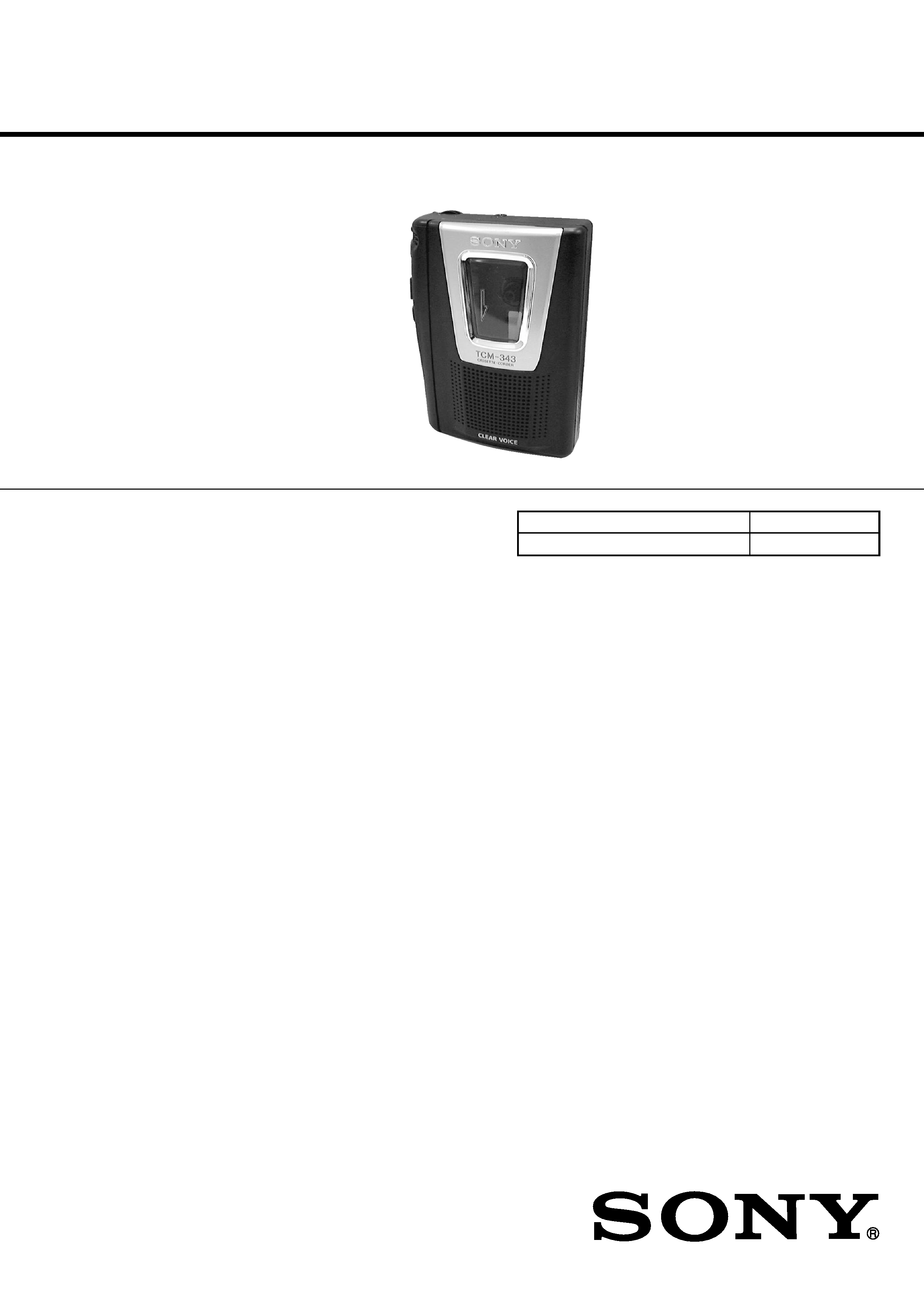
TCM-343
E Model
Chinese Model
SERVICE MANUAL
CASSETTE-CORDER
SPECIFICATIONS
Model Name Using Similar Mechanism
NEW
Tape Transport Mechanism Type
MT-323-118
Recording system
2-track 1 channel monaural
Frequency range
250 - 6 300 Hz
Speaker
Approx. 3.6 cm (1 7 / 16 in.) dia.
Power output (at 10% harmonic
distortion)
250 mW
Output
Earphone jack (minijack) for 8 -
300
earphone
Power requirements
· 3 V DC batteries R6 (AA)
× 2
· External DC 3 V power sources
Dimensions (w/h/d) (incl. projecting
parts and controls)
Approx. 112
× 36.6 × 90.3 mm
(4 1 /2
× 1 1 /2 × 3 5 /8 in.)
Mass (not incl. batteries)
Approx. 180 g (6.4 oz.)
Design and specifications are subject
to change without notice.
Ver 1.0 2000. 11
-- 2 --
Notes on chip component replacement
· Never reuse a disconnected chip component.
· Notice that the minus side of a tantalum capacitor may be
damaged by heat.
Flexible Circuit Board Repairing
· Keep the temperature of soldering iron around 270°C
during repairing.
· Do not touch the soldering iron on the same conductor of the
circuit board (within 3 times).
· Be careful not to apply force on the conductor when soldering
or unsoldering.
TABLE OF CONTENTS
1. GENERAL ·········································································· 2
2. DISASSEMBLY
2-1. Lid Sub Assy, Cassette ···················································· 3
2-2. Main Board, Mechanism Deck ······································· 3
2-3. Belt ·················································································· 4
2-4. "Head, Magnetic", Pinch Roller ····································· 4
3. MECHANICAL ADJUSTMENT ·································· 5
4. ELECTRICAL ADJUSTMENT ···································· 5
5. DIAGRAMS
6-1. IC Block Diagrams ························································· 6
6-2. Block Diagram ································································ 7
6-3. Schematic Diagram ························································· 9
6-4. Printed Wiring Board ···················································· 11
6. EXPLODED VIEWS
6-1. Cabinet Section ····························································· 13
6-2. Mechanism Deck Section-1 (MT-323-118) ·················· 14
6-3. Mechanism Deck Section-2 (MT-323-118) ·················· 15
7. ELECTRICAL PARTS LIST ······································· 16
SECTION 1
GENERAL
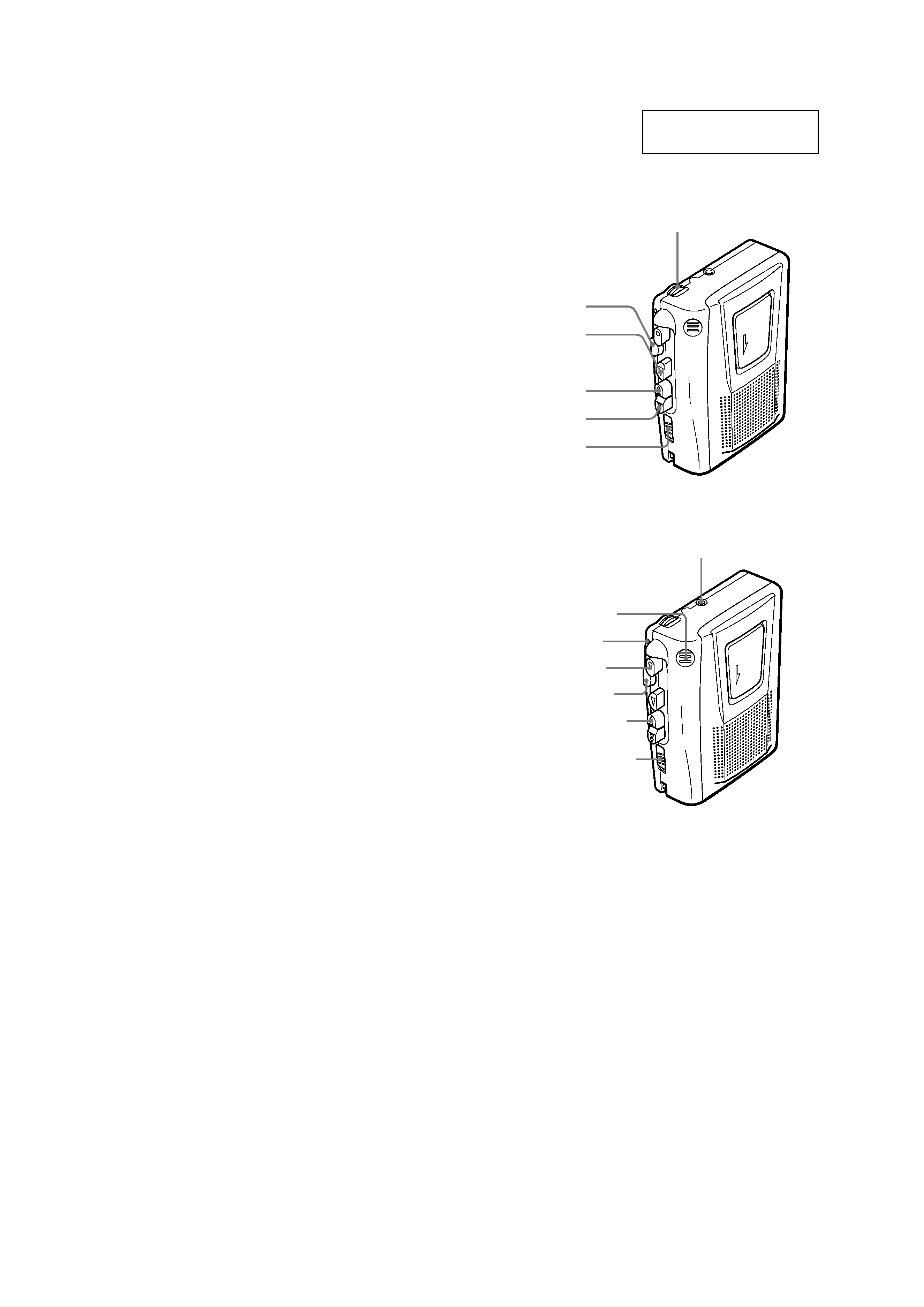
This section is extracted
from instruction manual.
VOL
M
FF/CUE
x
STOP
m
REW/REVIEW
PAUSE .
N
PLAY
EAR
z
REC
x
STOP
m
REW/
REVIEW
PAUSE .
Built-in mic
Micrófono incorporado
Microfone incorporado
BATT
-- 3 --
SECTION 2
DISASSEMBLY
Note :
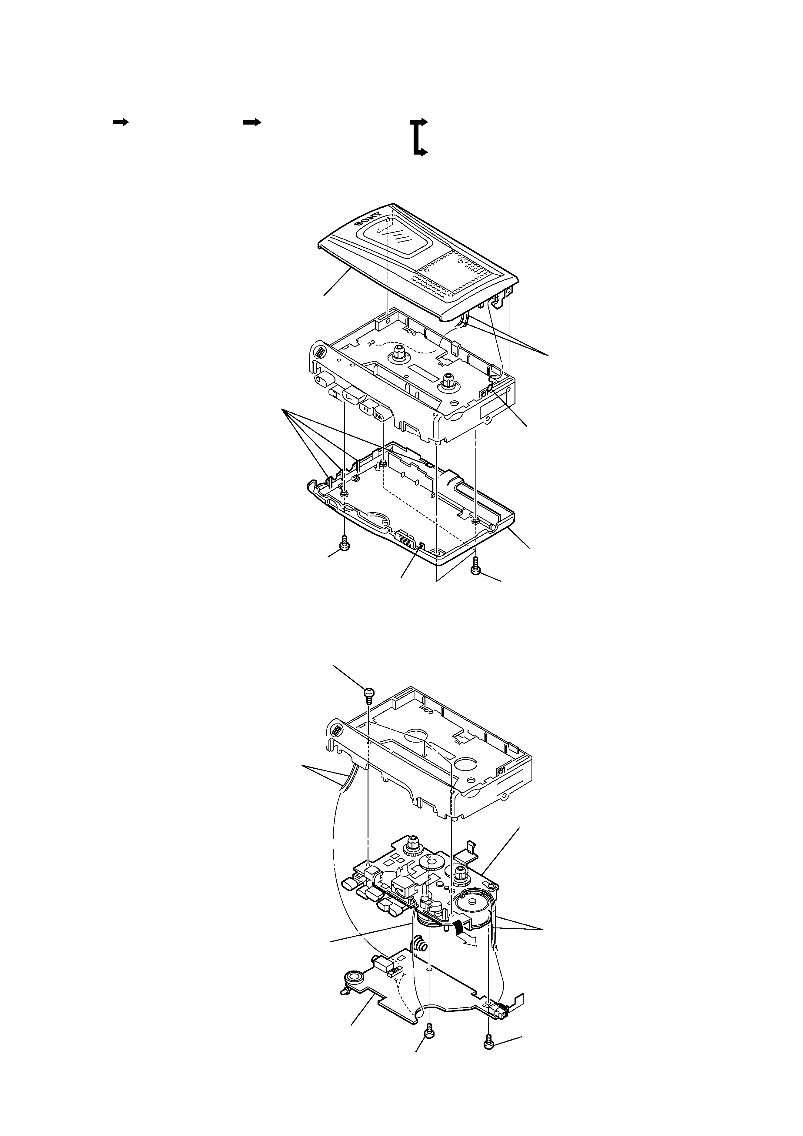
Follow the disassembly procedure in the numerical order given.
· The equipment can be removed using the following procedure.
2-1. LID SUB ASSY, CASSETTE
2-2. MAIN BOARD, MECHANISM DECK
4
two cords(SP901)
6
spring, cassette
5
lid sub assy, cassette
four claws
claw
3
cabinet (rear)
2
screw
(IB LOCK)
1
three screws
(B1.7
× 9)
8
mechanism deck
6
main board
4
cord
(HRP901)
5
two cords
(MIC901)
3
two cords
(M901)
1
screw
(1.7)
2
screw
(M1.4)
7
three screws
(IB LOCK)
Lid Sub Assy, Cassette
Main Board, Mechanism Deck
Belt
Set
"Head, Magnetic", Pinch Roller
-- 4 --
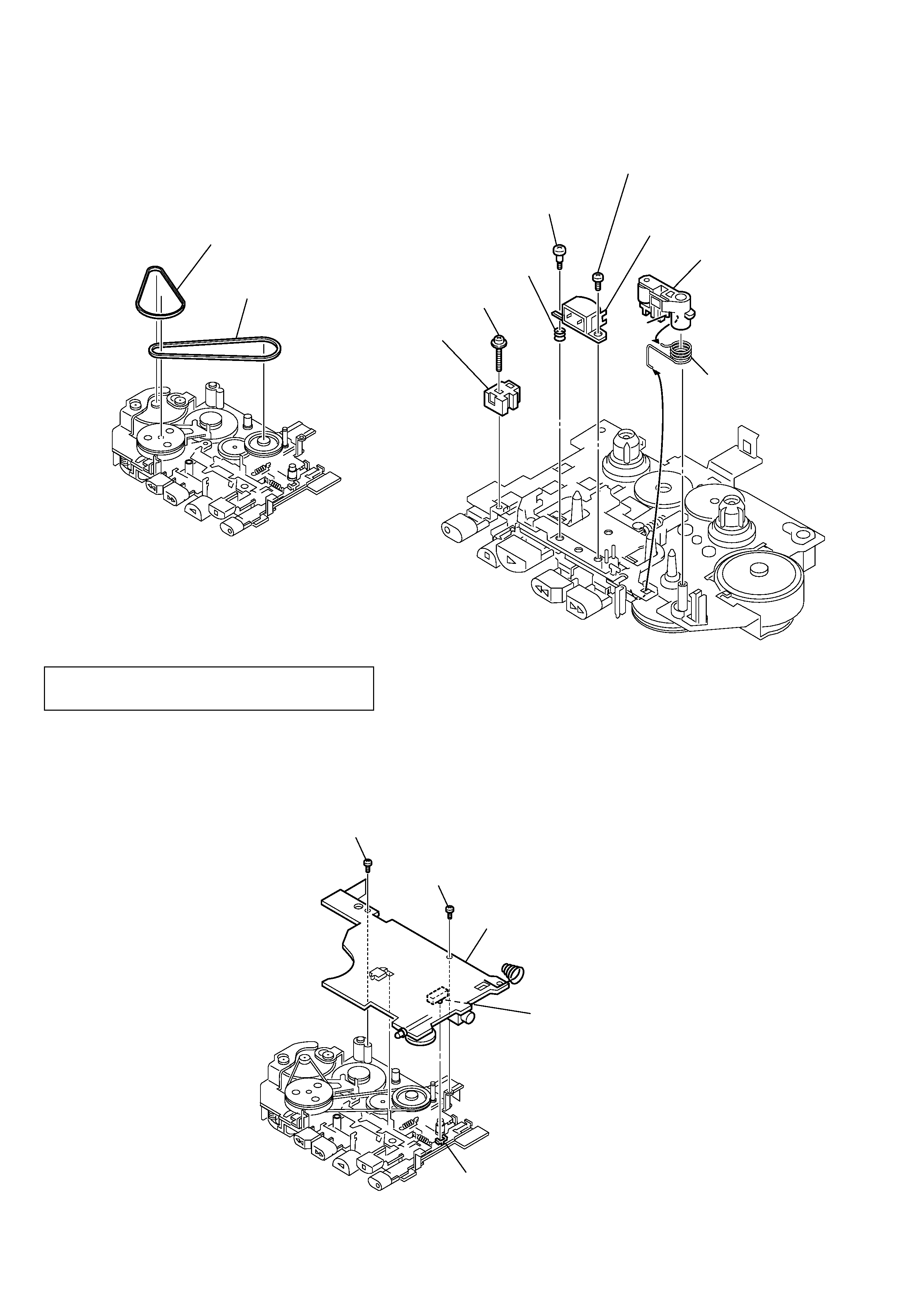
2-3. BELT
1
belt (capstan)
2
belt (fr)
screw
(M1.4)
screw
(1.7)
main board
S101 (REC)
REC lever
2-4. "HEAD, MAGNETIC", PINCH ROLLER
INSTALLATION MAIN BOARD
On installation MAIN board, adjust to the S101 and
the REC lever.
8
screw (M1.4)
6
head, magnetic
(HRP901)
3
pinch roller
2
4
screw (1.4)
5
screw (M1.4
× 3.8)
9
head, magnetic
(HE901)
1
lever (pinch roller)
7
spring (azimuth),
compression
-- 5 --
SECTION 3
MECHANICAL ADJUSTMENT
PRECAUTION
1.
Clean the following parts with a denatured-alcohol-moistened
swab :
playback head
pinch roller
capstan
rubber belt
2.
Demagnetize the playback head with a head demagnetizer.
3.
Do not use a magnetized screwdriver for the adjustments.
4.
The adjustments should be performed with the rated power
supply voltage (DC 3.0 V) unless otherwise noted.
Torque Measurement
SECTION 4
ELECTRICAL ADJUSTMENT
PRECAUTION
· Supplied voltage
: 3.0 V
· Switch and control position
VOL control
: mechanical mid
PAUSE switch : OFF
Test tape
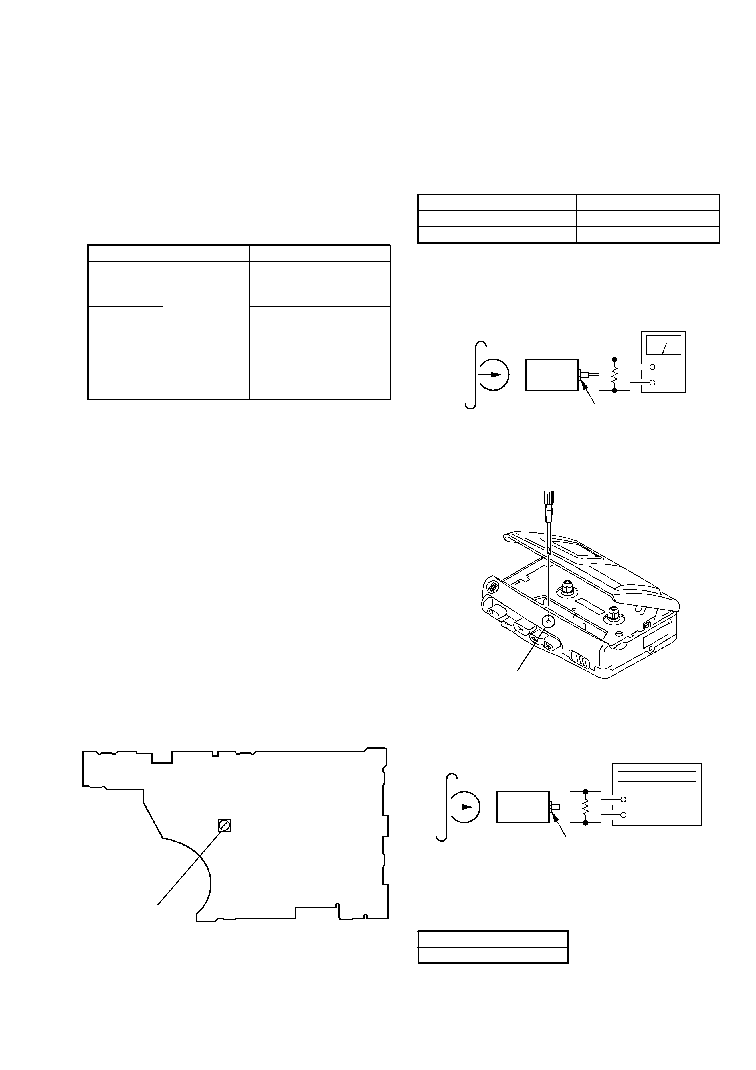
REC/PB Head Azimuth Adjustment
Procedure :
1.
Model : playback
2.
Turn the adjustment screw to obtain the maximum readig on
level meter.
Note : Several peaks may appear, but take the maximum.
Adjustment Location :
Tape Speed Adjustment
Procedure :
1.
Playback WS-48A (tape center part) in the FWD state and adjust
RV601 so that the frequency counter reading becomes
3,000 Hz.
Specification Value :
2.
Check that frequency counter reading is within 2% of reading
of step 1.
Digital frequency counter
2,970 to 3,030 Hz
Type
WS-48A
P-4-A063
Signal
3 kHz, 0 dB
6.3 kHz, - 10dB
Used for
tape speed adjustment
head azimuth adjustment
Mode
Torque Meter
Meter Reading
more than 1.96 mN · m
(more than 20 g · cm)
(more than 0.28 oz · inch)
more than 4.90 mN · m
(more than 50 g · cm)
(more than 0.69 oz · inch)
0.05 0.29 mN · m
(0.5 3 g · cm)
(0.007 0.04 oz · inch)
FWD
CQ-102C
FWD
back tension
FF, REW
CQ-201B
+
test tape
WS-48A
(3 kHz, 0 dB)
set
EAR jack (J102)
32
frequency counter
RV601
Adjustment Location : main board (conductor side)
+
test tape
P-4-A063
(6.3 kHz, -10 dB)
set
EAR jack (J102)
10 k
level meter
adjustment screw
