1
STR-W555
AEP Model
UK Model
E Model
Australian Model
Chinese Model
Tourist Model
SPECIFICATIONS
SERVICE MANUAL
FM STEREO/FM-AM RECEIVER
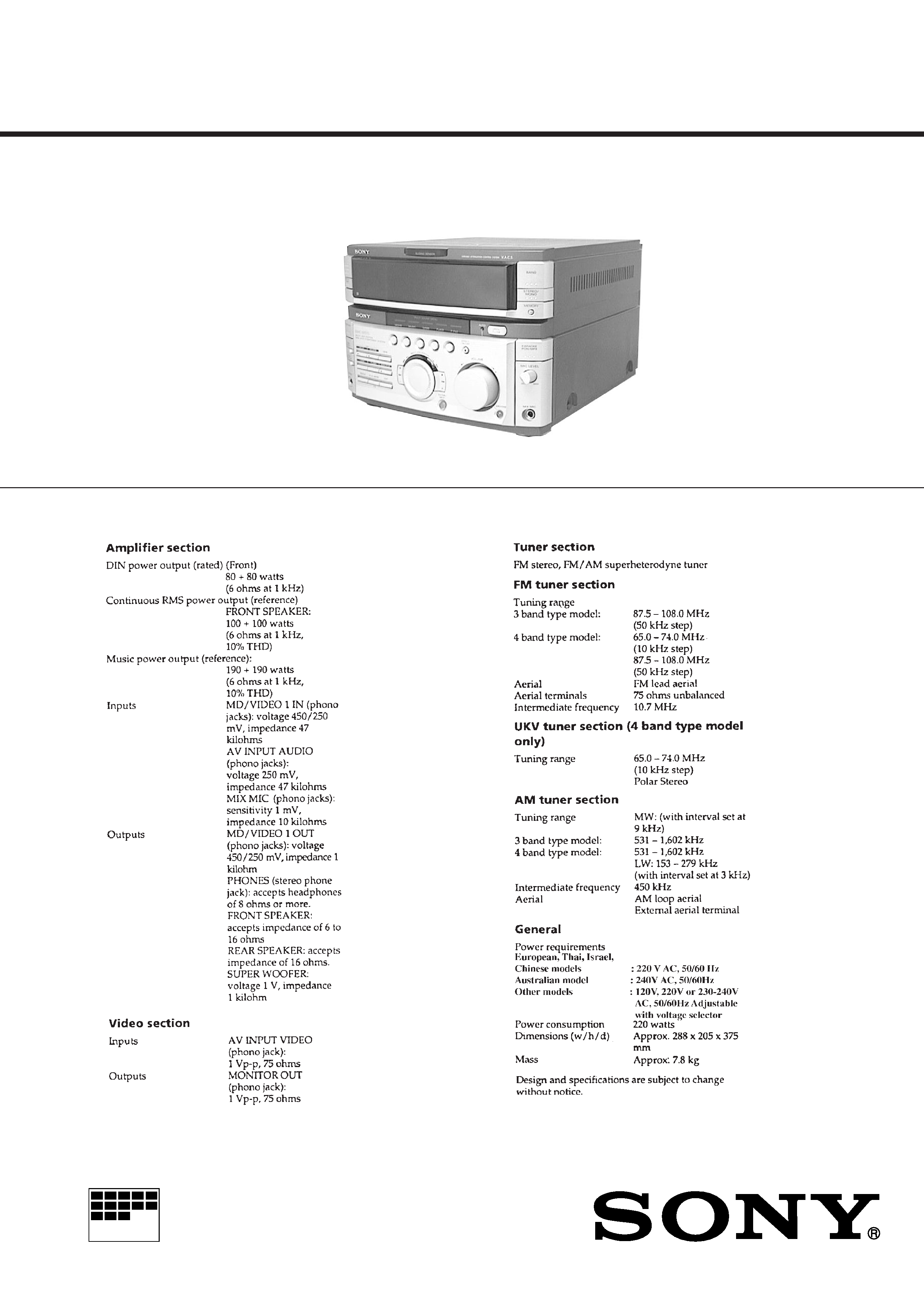
STR-W555 is the tuner and amplifier
section in MHC-W555.
MICROFILM
Photo : E model

2
Notes on chip component replacement
· Never reuse a disconnected chip component.
· Notice that the minus side of a tantalum capacitor may be
damaged by heat.
Flexible Circuit Board Repairing
· Keep the temperatur e of soldering ir on around 270°C
during repairing.
· Do not touch the soldering iron on the same conductor of the
circuit board (within 3 times).
· Be careful not to apply force on the conductor when soldering
or unsoldering.
SAFETY-RELATED COMPONENT WARNING !!
COMPONENTS IDENTIFIED BY MARK ! OR DOTTED LINE
WITH MARK ! ON THE SCHEMATIC DIAGRAMS AND IN
THE PARTS LIST ARE CRITICAL TO SAFE OPERATION.
REPLACE THESE COMPONENTS WITH SONY PARTS
WHOSE PART NUMBERS APPEAR AS SHOWN IN THIS
MANUAL OR IN SUPPLEMENTS PUBLISHED BY SONY.
MIN
MIX MIC 2
MIX MIC 1
MAX
MALAYSIA
MALAYSIA
MALAYSIA
MALAYSIA
JAPAN
THAI
MALAYSIA
MALAYSIA
MALAYSIA
MALAYSIA
MALAYSIA
MALAYSIA
JAPAN
LABEL MODEL NUMBER
No.
PTY button
PRODUCT
COUNTRY
MODEL
POWER CORD
JACK (MIC2)
(Refer to Fig 3)
NOT USED
USED
NOT USED
NOT USED
NOT USED
NOT USED
NOT USED
NOT USED
NOT USED
NOT USED
NOT USED
NOT USED
NOT USED
NOT USED
NOT USED
USED
NOT USED
NOT USED
NOT USED
NOT USED
NOT USED
NOT USED
NOT USED
USED
4-210-483-0
4-210-483-0
4-210-481-0
4-210-481-0
4-210-482-0
4-210-482-1
4-210-479-0
4-210-480-0
4-210-483-1
4-210-479-0
4-210-492-1
4-210-481-0
LABEL MODEL NUMBER
(Refer to Fig 1)
PTY button
(Refer to Fig 2)
AEP
East European
,CIS
Saudi Arabia
,Taiwan
NOT USED
NOT USED
4-210-479-0
Singapore
,Malaysia
Saudi Arabia
Thai
Israel
Argentine
Australian
UK
E
Chinese
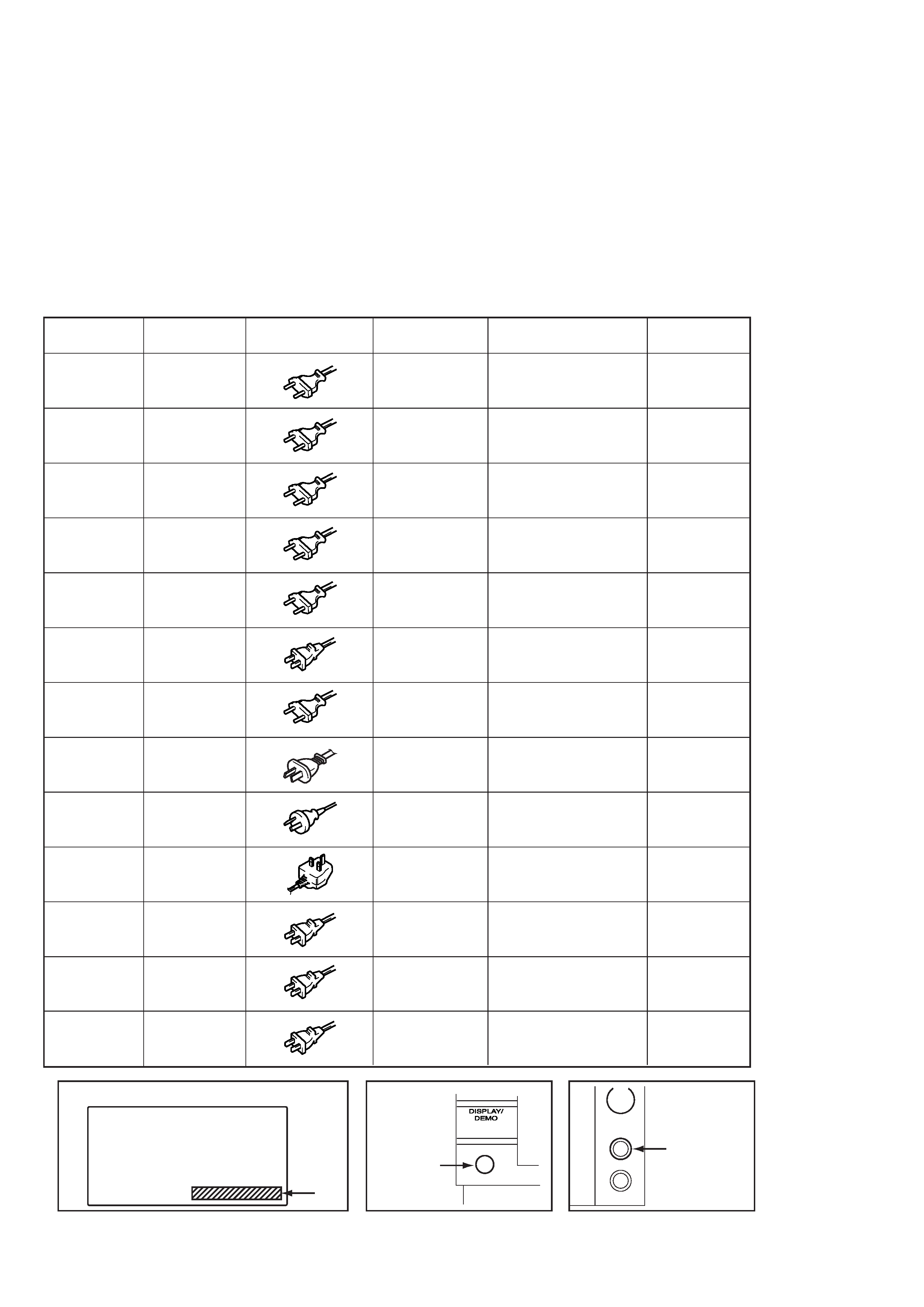
Fig 1.
Fig 2.
Fig 3.
Tourist
Jack (MIC 2)

3
TABLE OF CONTENTS
1. GENERAL ........................................................................... 4
2. DISASSEMBLY
· Sliding Panel Assembly ...................................................... 5
3. SERVICE MODE .............................................................. 6
4. ELECTRICAL ADJUSTMENT ................................... 11
5. DIAGRAMS
5-1. Circuit Boards Location ...................................................... 12
5-2. Block Diagrams
· Tuner Section (AEP, UK model) ..................................... 13
· Tuner Section (East European, CIS model) ..................... 15
· Main Section .................................................................... 17
· Power Section .................................................................. 19
5-3. Schematic Diagram
Tuner (AEP, UK model) Section .................................... 23
5-4. Printed Wiring Board
Tuner (AEP, UK model) Section .................................... 25
5-5. Printed Wiring Board
Tuner (East European, CIS model) Section ................... 26
5-6. Schematic Diagram
Tuner (East European, CIS model) Section ................... 27
5-7. Printed Wiring Board Main Section .............................. 29
5-8. Schematic Diagram Main (1/2) Section ........................ 31
5-9. Schematic Diagram Main (2/2) Section ........................ 33
5-10. Schematic Diagram AV/Mic Section .......................... 35
5-11. Printed Wiring Board AV/Mic Section ....................... 36
5-12. Schematic Diagram Power Amp Section ................... 37
5-13. Printed Wiring Board Power Amp Section ................. 39
5-14. Schematic Diagram Display Section .......................... 41
5-15. Printed Wiring Board Display Amp Section .............. 43
5-16. Schematic Diagram Sliding Panel Section ................. 45
5-17. Printed Wiring Board Sliding Panel Section .............. 47
5-18. Printed Wiring Board Trans Section ........................... 49
5-19. Schematic Diagram Trans Section ............................. 51
5-20. IC Block Diagrams ........................................................... 52
5-21. IC Pin Function ................................................................ 56
6. EXPLODED VIEWS
6-1. Case and Sliding Panel Section ........................................... 59
6-2. Front Panel Section ............................................................. 60
6-3. Slide Mechanism Section .................................................... 61
6-4. Circuit Boards and Back Panel Section .............................. 62
7. ELECTRICAL PARTS LIST ........................................ 63

4
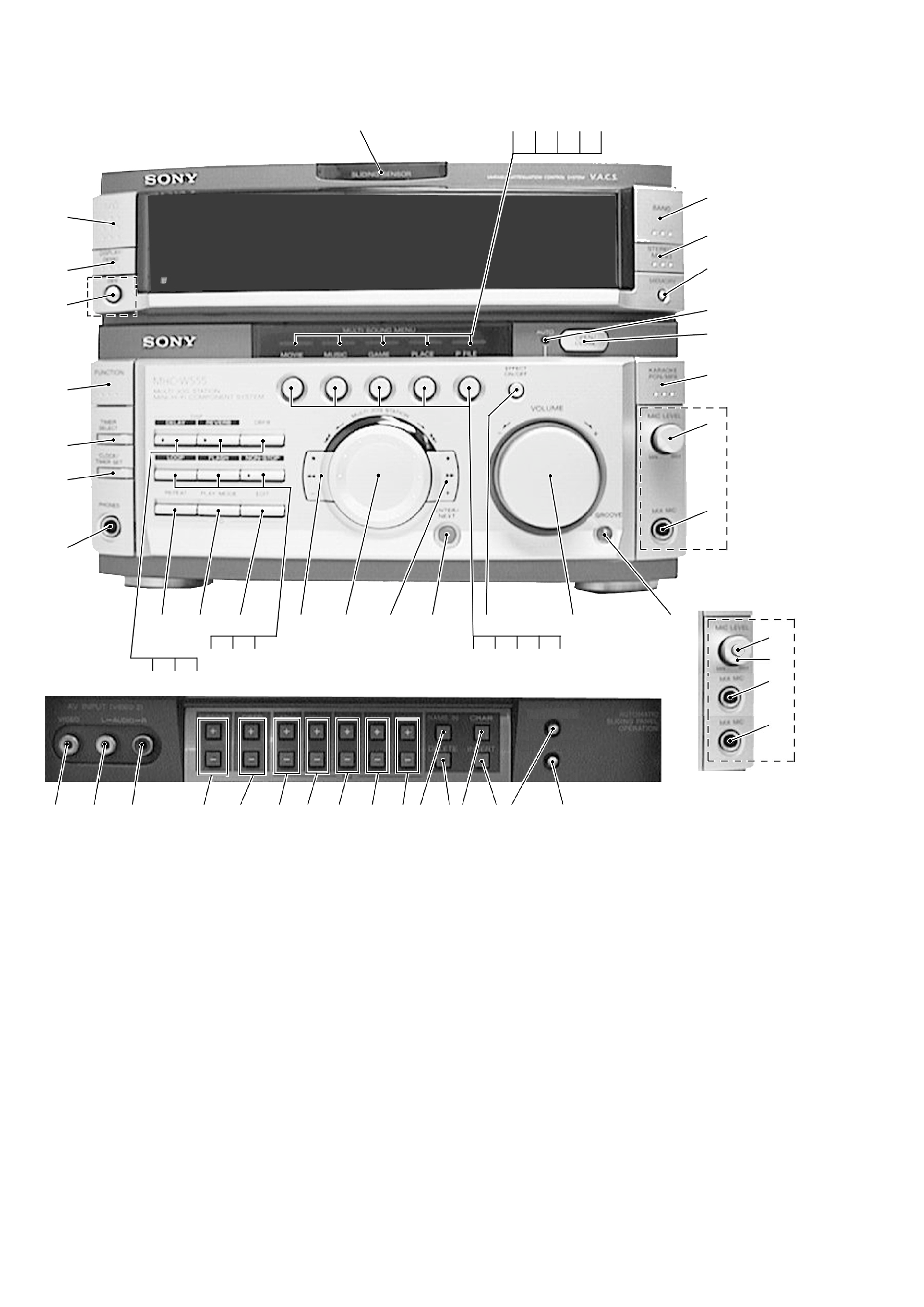
LOCATION OF PARTS AND CONTROLS
1
1/u (Power) button
2
SLIDING SENSOR window
3
MOVIE indicator
4
MUSIC indicator
5
GAME indicator
6
PLACE indicator
7
P FILE indicator
8
TUNER/BAND button
9
STEREO/MONO button
10 MEMORY button
11 AUTO indicator
12 OPEN/CLOSE button
13 KARAOKE PON/MPX button
14 MIC LEVEL knob
15 MIX MIC jack (EXCEPT EA3 (Japan
Product), JE model)
MIC 1 jack (EA3 (Japan Product), JE
model)
16 GROOVE button and indicator
17 VOLUME knob
18 EFFECT ON/OFF button and indicator
19 P FILE button
20 PLACE button
SECTION 1
GENERAL
Front Panel
45
46
47
48
49
50 51 52
53 54 55 56 57 58 59
60
43 MIC 2 jack (EA3 (Japan Product), JE
model)
44 ECHO LEVEL knob
(EA3 (Japan Prooduct), JE model)
45 VIDEO (AV INPUT (VIDEO 2)) jack
46 AUDIO-L (AV INPUT (VIDEO 2)) jack
47 AUDIO-R (AV INPUT (VIDEO 2)) jack
48 SURROUND +/ buttons
49 DBFB +/ buttons
50 63Hz +/ buttons
51 250Hz +/ buttons
52 1kHz +/ buttons
53 4kHz +/ buttons
54 16kHz +/ buttons
55 NAME IN button
56 DELETE button
57 CHAR button
58 INSERT button
59 OPEN SENSOR ON/OFF button
60 EQ MEMORY button
· Abbreviation
EA3 : Saudi Arabia model.
JE
: Tourist model.
21 GAME button
22 MUSIC button
23 MOVIE button
24 ENTER/NEXT button and indicator
25 ) + button and indicator
26 = C MULTI JOG STATION c
+ dial
27 0 button and indicator
28 CD EDIT button
29 CD PLAY MODE button
30 CD REPEAT button
31 NON-STOP button and indicator
32 FLASH button
33 LOOP button
34 DBFB button
35 DSP REVERB button and indicator
36 DSP DELAY button and indicator
37 PHONES jack
38 CLOCK/TIMER SET button
39 TIMER SELECT button
40 FUNCTION button
41 PTY button (AEP, UK model)
42 DISPLAY/DEMO button
2
19
20
21
22
23
16
17
18
9
10
11
12
13
14
15
34 56
7
8
24
25
26
27
1
37
38
39
41
42
40
34
35
36
31
29
30
32
33
28
EXCEPT
EA3 (Japan
Product), JE
EA3 (Japan
Product), JE
44
43
15
14

5
SECTION 2
DISASSEMBLY
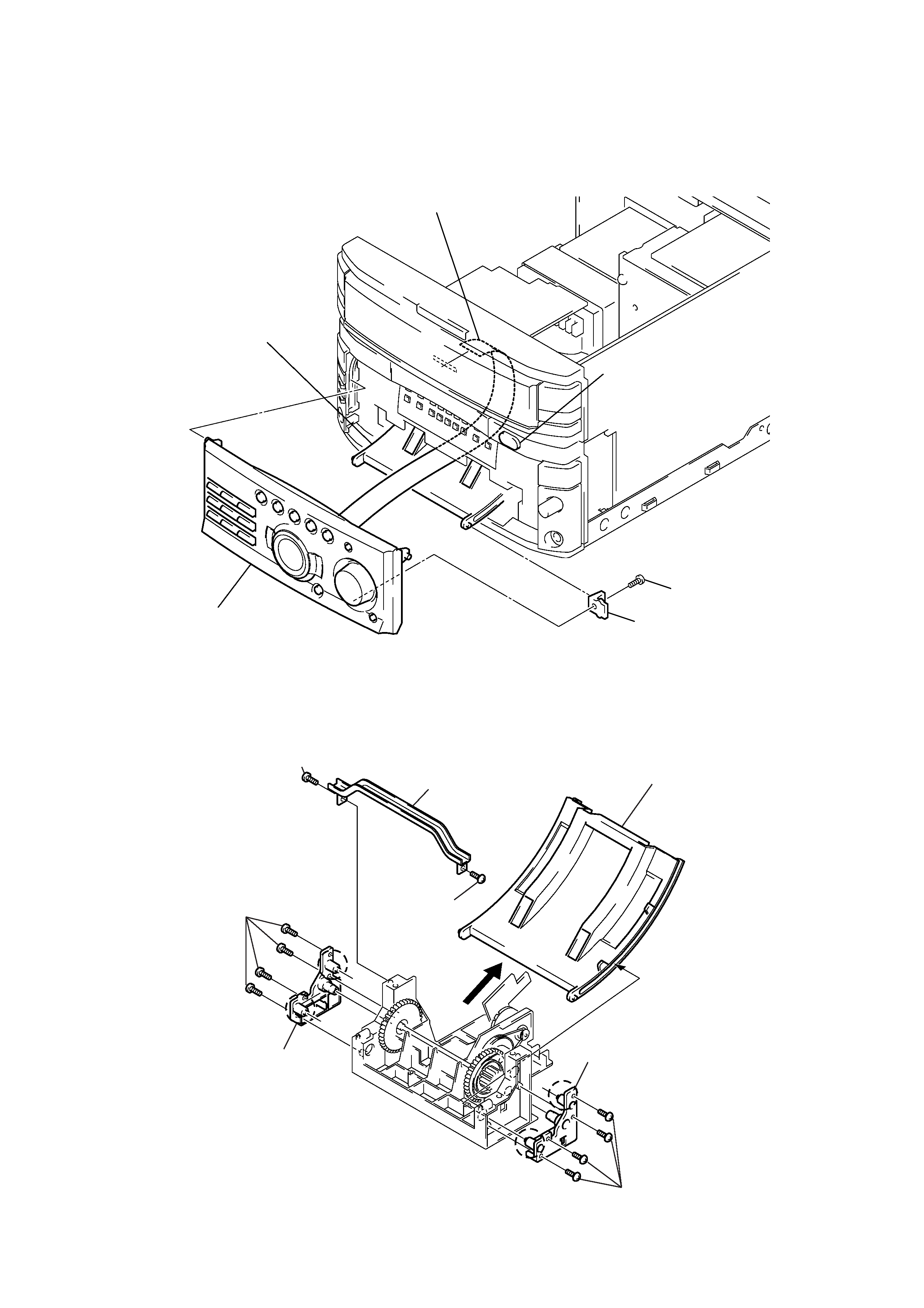
Note: Follow the disassembly procedure in the numerical order given.
· SLIDING PANEL ASSEMBLY
4 Flat type cable (19 core)
2 Screw (BVTP 3x8)
3 Holder level
5 Sliding panel assembly
Slide mechanism
1 Push the OPEN/CLOSE button to
open the Sliding panel assembly.
1 Screw (BVTP2.6x8)
4 Four screw
(BVTP2.6x8)
5 Holder (L) assembly
a
a
b
b
6 Four screw (BVTP2.6x8)
7 Holder (R) assembly
8 Remove the Level slider direction of arrow.
2 Screw
(BVTP2.6x8)
3 Top bracket
NOTE FOR INSTALLATION (LEVEL SLIDER)
NOTE :
Attach in the reverse order, but make sure the rollers (
a, b) of the
holder (L) assembly and holder (R) assembly fit into the grooves of
the level slider.
