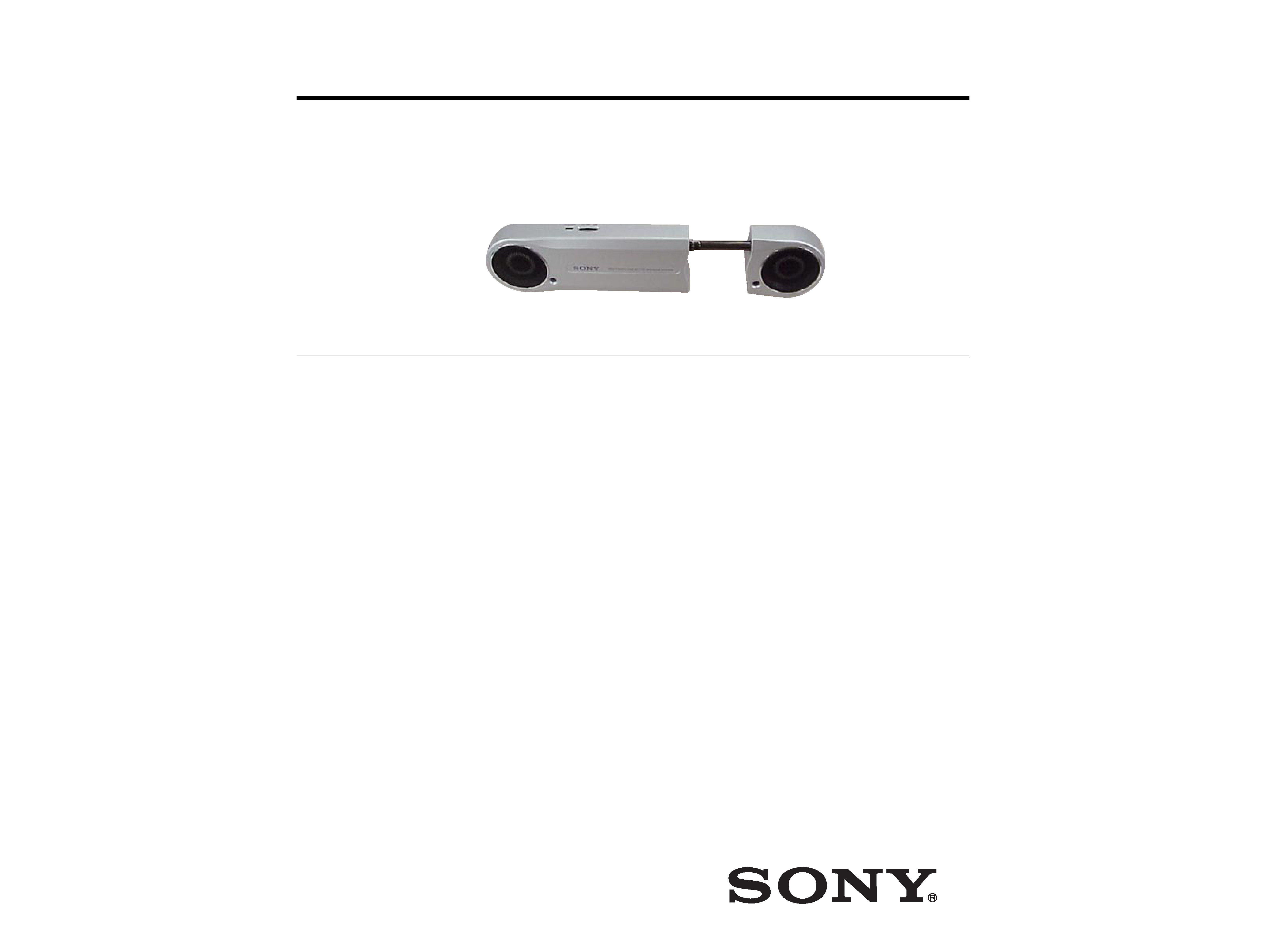
SRS-T100PC
US Model
Canadian Model
AEP Model
E Model
SERVICE MANUAL
ACTIVE SPEAKER SYSTEM
SPECIFICATIONS
Ver 1.0 2003. 02
Sony Corporation
Personal Audio Company
Published by Sony Engineering Corporation
9-877-119-01
2003B167800-1
© 2003.02
USB section
USB connector
Type A plug
USB cord length
Approx. 51 cm (20 1/8 inch)
Compliant OS
Windows XP, Windows 2000,
Windows Me, Windows 98SE
Complies with the standard
operating systems that are
installed
Compliant computer
IBM PC/AT or compatible
computers
Recommended CPU
Pentium II 266MHz or faster
Amplifier section
Maximum output power 0.6 W + 0.6 W
(10 % T.H.D., 1 kHz, 20
)
Input
USB terminal
Speaker section
Enclosure type
Full range, Bass reflex
Speaker system
34 mm magnetically shielded
Impedance
20
Rated input power
1 W
General
Power supply
USB bus power compliant
(5 V, 500 mA)
Dimensions (w
× h × d) Approx. 209 × 53 × 24.2 mm
(8 1/4
× 2 1/8 × 31/32 inch)
(When extended approx.
428
× 53 × 24.2 mm,
16 7/8
× 2 1/8 × 31/32 inch)
Mass
Approx. 250 g (9 oz.)
Supplied accessories
Operating instructions (1)
Design and specifications are subject to change without
notice.

2
SRS-T100PC
TABLE OF CONTENTS
Notes on chip component replacement
·Never reuse a disconnected chip component.
· Notice that the minus side of a tantalum capacitor may be dam-
aged by heat.
1. GENERAL ·········································································· 3
2. DIAGRAMS
2-1. Printed Wiring Board ······················································ 5
2-2. Schematic Diagram ························································· 6
2-3. IC Block Diagrams ························································· 7
3. EXPLODED VIEWS
3-1. Left Speaker Section ······················································· 9
4. ELECTRICAL PARTS LIST ······································· 10

3
SRS-T100PC
SECTION 1
GENERAL
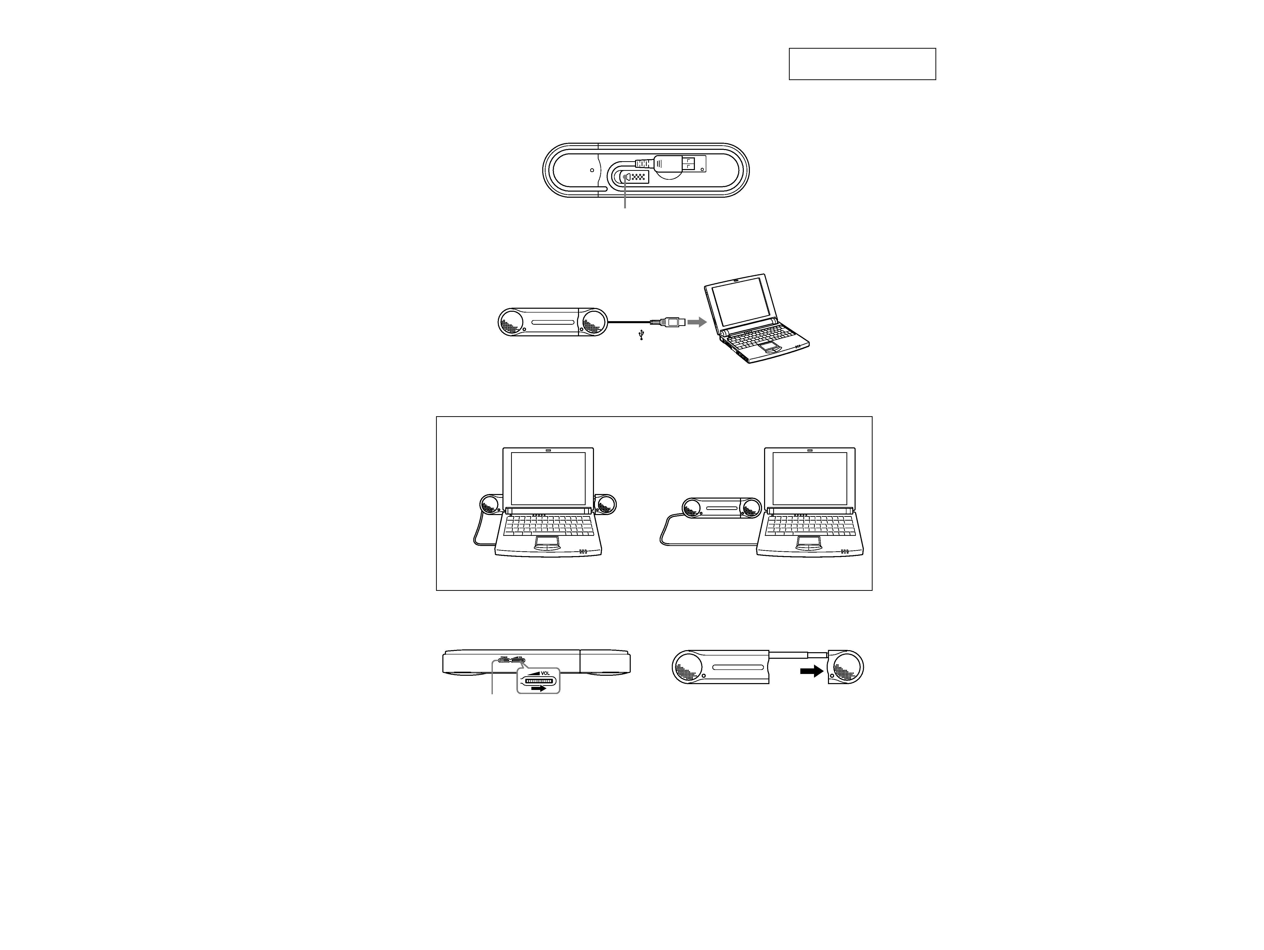
This section is extracted from
instruction manual.
stand
Left speaker
Right speaker
Power indicator
VOLUME
To increase the volume,
rotate in the direction of
the arrow; to decrease the
volume, rotate in the
opposite direction.
Type A plug
To the USB
type A jack of
a computer
Image

4
SRS-T100PC
SECTION 2
DIAGRAMS
Note on Schematic Diagrams:
· All capacitors are in µF unless otherwise noted. pF: µµF
50 WV or less are not indicated except for electrolytics
and tantalums.
· All resistors are in
and 1/4 W or less unless otherwise
specified.
· C : panel designation.
· A : B+ Line.
·Voltage and waveform are connected and measured in
the USB port of PC.
·Voltages are taken with a VOM (Input impedance 10 M
).
Voltage variations may be noted due to normal produc-
tion tolerances.
·Waveform is taken with a oscilloscope. Voltage variations
may be noted due to normal production tolerances.
· Circled numbers refer to Waveforms.
· Signal path.
F
: AUDIO
Note on Printed Wiring Boards:
· Y : parts extracted from the conductor side.
· b : Pattern from the side which enables seeing.
· Indication of transistor.
C
B
These are omitted.
E
Q
·Waveform
1 IC1 w; (XTO)
4.4 Vp-p
83.3 ns
1V/DIV, 40ns/DIV

5
5
SRS-T100PC
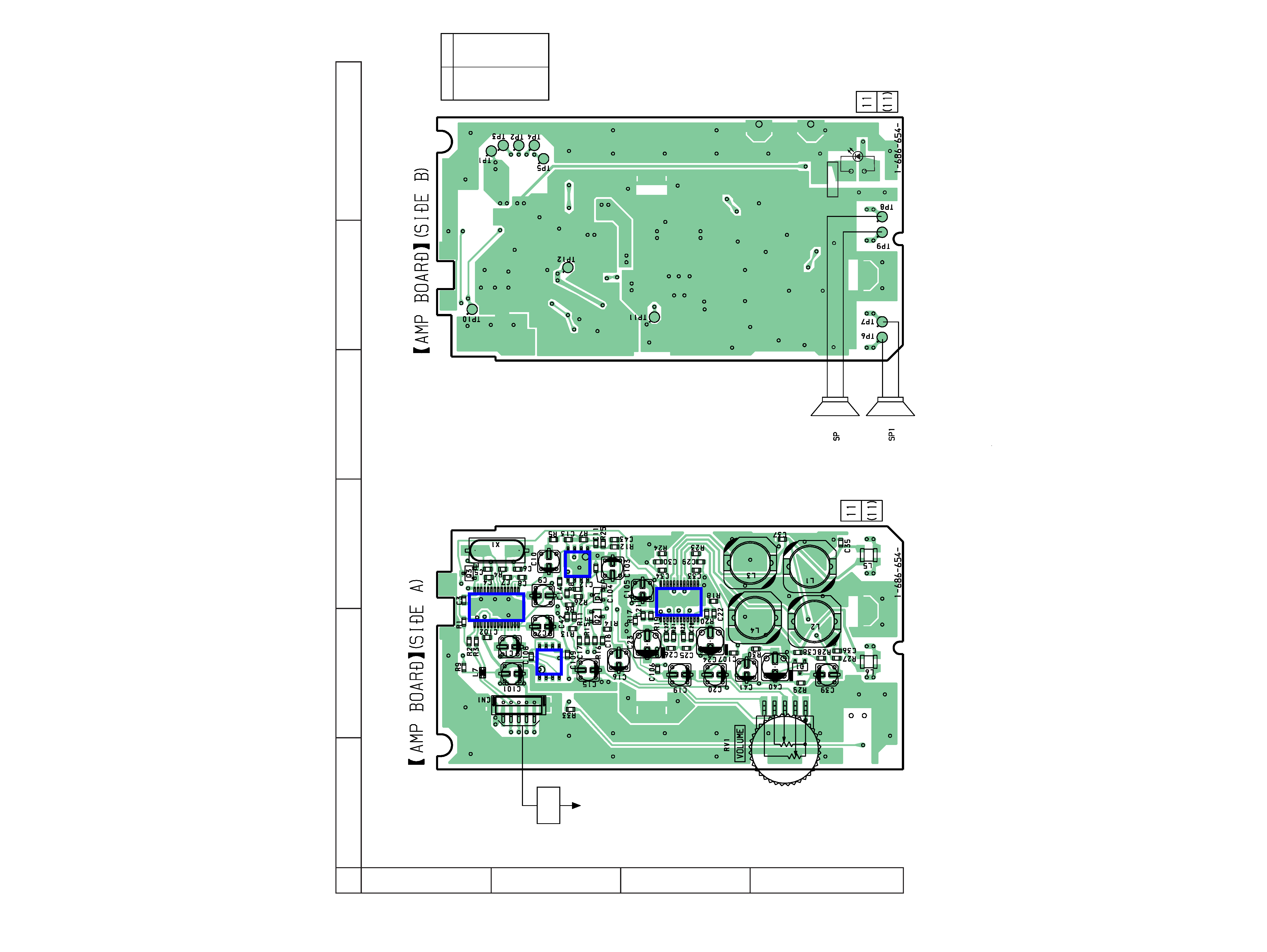
2-1. Printed Wiring Board
Ref. No.
Location
D1
D-2
D2
D-6
IC1
A-3
IC2
B-3
IC3
C-3
IC4
B-2
Q1
B-3
Q2
B-2
Q3
A-3
· Semiconductor
Location
(L CH)
(R CH)
2
(+)
(-)
(+)
(-)
D2
POWER
12
A
B
C
D
345
6
TO PC
USB
CABLE
IC3
IC1
IC2
IC4
