MICROFILM
SERVICE MANUAL
J VIDEO CASSETTE RECORDER
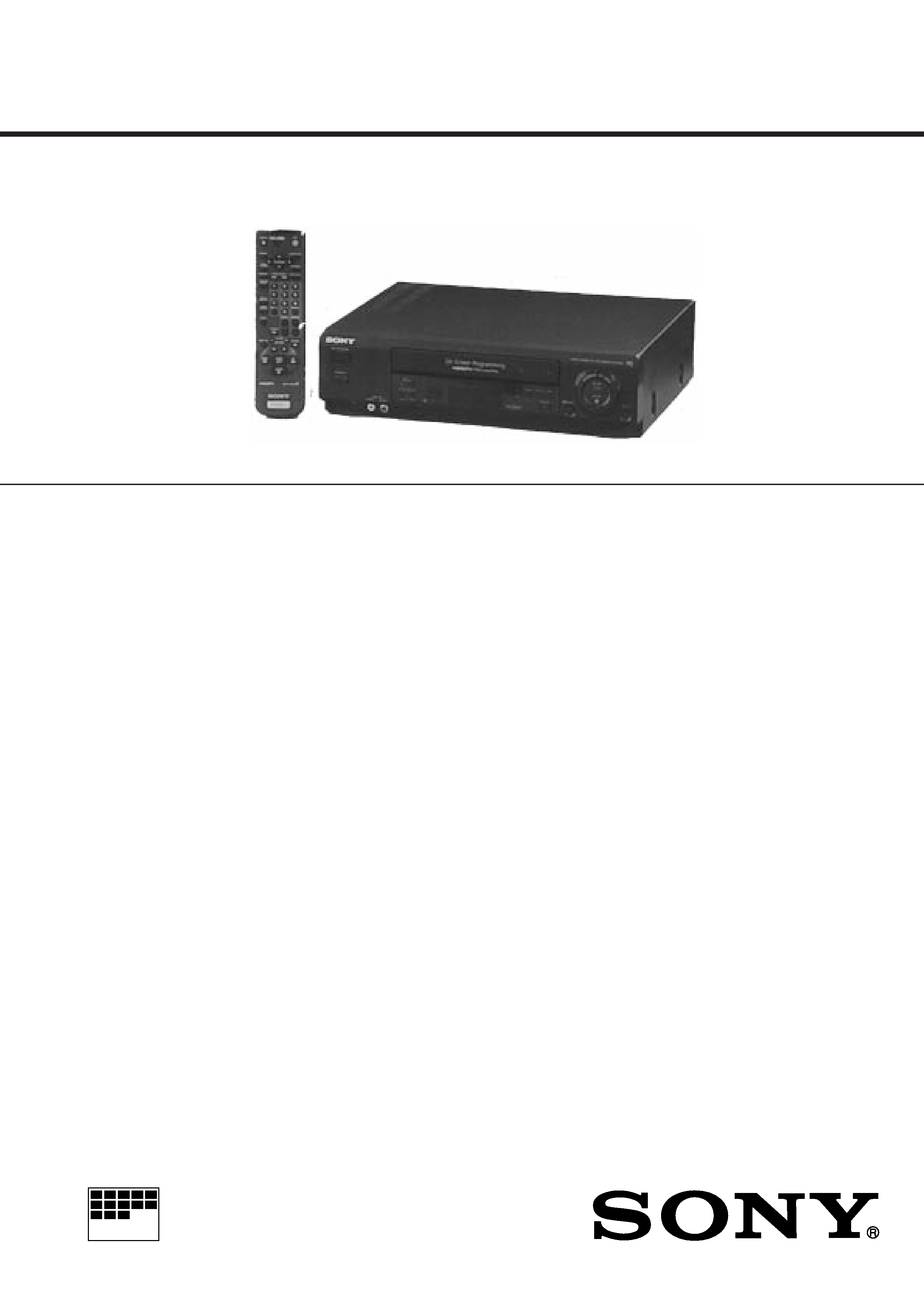
Photo : SLV-E280UX
AEP Model
SLV-E120AE/E220AE/VP1/VP2/E270CP/VC1/VC2/E280CP/VC1/VC2
UK Model
SLV-E220UY/E280UX
SPECIFICATIONS
System (SLV-E220UY/E280UX)
Channel coverage
PAL (I) :
UHF B21 - B69
RF output signal
UHF I21 - 69 CH
Aerial out
75-ohm asymmetrical aerial socket
System (EXCEPT SLV-E220UY/E280UX)
Channel coverage
PAL (B, G) :
VHF E2 - E12
(comprese channel C)
(A - H only For Italy)
UHF E21 - E69
CATV S01 - S03, S1 - S20
HYPER BAND S21 - S41
Intermediate frequency
F1 - 1 Video 38.9MHz
F2 - 1 Audio 33.4MHz
RF output signal
UHF G22 - 69
Aerial out
75-ohm asymmetrical aerial socket
Inputs/outputs
ÚEURO-AV1
21-pin
Video input
: pin 20
Audio input
: pins 2 and 6
Video output
: pin 19
Audio output
: pins 1 and 3
J EURO-AV2 (2nd Scart)
21-pin
(Except SLV-E120AE/E220 Series)
Video input
: pin 20
Audio input
: pins 2 and 6
Front Line In (SLV-E280 Series)
VIDEO IN, Phono jack (1)
Input signal : 0.5 1.5 Vp-p
75 ohms, unbalanced, sync negative
AUDIO IN, Phone jack (1)
Input level : 8 dBs
(0 dBs = 0.755 Vrms)
Input impedance : more than
47 kilohoms
General
Power requirements
220 240 V AC, 50 Hz
Power consumption
17 W
5W (standby)(SLV-E120AE/E220 Series)
6W (standby)(Except SLV-E120AE/E220 Series)
Operating temperature
5
°C to 40°C
Storage temperature
20
°C to 60°C
Dimensions
Approx. 360 x 97 x 298 mm (w/h/d)
including projecting parts and controls
Mass
Approx. 3.7 kg
Supplied accessories
Remote commander (1)
R6 (size AA) batteries (2)
Aerial cable (1)
Mains lead (1)
Design and specifications are subject to change without notice.
SLV-E120AE/E220AE/UY/VP1/VP2/E270CP/VC1/VC2/
E280CP/UX/VC1/VC2
RMT-V206C/V206D/V207C/V207D/V207E/V207G/V207H

2
SAFETY-RELATED COMPONENT WARNING!!
COMPONENTS IDENTIFIED BY MARK
! OR DOTTED
LINE WITH MARK
! ON THE SCHEMATIC DIAGRAMS AND
IN THE PARTS LIST ARE CRITICAL TO SAFE OPERATION.
REPLACE THESE COMPONENTS WITH SONY PARTS
WHOSE PART NUMBERS APPEAR AS SHOWN IN THIS
MANUAL OR IN SUPPLEMENTS PUBLISHED BY SONY.
SAFETY CHECK-OUT
After correcting the original service problem, perform the following
safety check before releasing the set to the customer :
4. Look for parts which, though functioning, show obvious
signs of deterioration. Point them out to the customer and
recommend their replacement.
5. Check the B+ voltage to see it is at the values specified.
1. Check the area of your repair for unsoldered or poorly-sol-
dered connections. Check the entire board surface for sol-
der splashes and bridges.
2. Check the interboard wiring to ensure that no wires are
"pinched" or contact high-wattage resistors.
3. Look for unauthorized replacement parts, particularly tran-
sistors, that were installed during a previous repair. Point
them out to the customer and recommend their replacement.

3
1.
GENERAL
Step 1 Setting up the remote commander ..................... 1-1
Step 2 Connecting the VCR .......................................... 1-1
Step 3 Tuning the TV to your VCR ............................... 1-1
Step 4 Selecting a language ........................................... 1-2
Step 5 Tuning the VCR to TV Channels ....................... 1-2
Step 6 Setting the Clock ................................................ 1-2
Additional Tuning Instructions ..................................... 1-3
Setting a Satellite Tuner ................................................ 1-3
Playing a Tape ............................................................... 1-3
Recording TV Programmes ........................................... 1-4
Recording TV Programmes using Video Plus + ........... 1-4
Playing/Searching at Various Speeds ............................ 1-5
Setting the Timer Manually ........................................... 1-5
Recording TV Programmes using the Quick Timer ...... 1-6
Checking/Cancelling Timer Settings ............................. 1-6
Searching using the index function ............................... 1-6
Editing with another VCR ............................................. 1-7E
Adjusting the Picture ..................................................... 1-7E
Visual index ................................................................... 1-7E
2.
DISASSEMBLY
1-1. Removal of Cabinet, Mechanism Unit and Main
Board ..................................................................... 2-1
Removing the Cabinet Parts .................................. 2-1
Removing the Mechanism Main Unit and the
CP-1 PWB Assembly ............................................. 2-1
l-2. Temporarily Setting Up and Connecting
CP-1 PWB Assembly ............................................. 2-3E
1-3. Installation of the Front Panel ................................ 2-3E
3. DIAGRAMS
Circuit Boards Location ................................................ 3-1
Overall wiring Diagram ................................................ 3-3
Mechanism Connection Diagram .................................. 3-5
Video Circuit Diagram .................................................. 3-6
System Control & Servo Circuit Diagram ................... 3-9
Audio Circuit Diagram .................................................. 3-12
Terminal & Input/ Output Selector Circuit Diagram
(SLV-E270 & E280 Series) ........................................... 3-14E
4. SCHEMATIC DIAGRAMS AND PRINTED
WIRING BOARDS
CP-1 Board (PW-A) Power Supply Circuit Diagram .... 4-1
CP-1 Board (AD-A) Terminal & Selector
(SLV-E270 & E280 Series) ........................................... 4-3
CP-1 Board (AD-A) Terminal Circuit Diagram
(SLV-E120AE/E220 Series) .......................................... 4-5
CP-1 Board (VA-A) Video & Audio Circuit Diagram
(SLV-E270 Series/E280CP/VC1/VC2) ......................... 4-7
CP-1 Board (VA-A) Video & Audio Circuit Diagram
(SLV-E120AE & E220 Series) ...................................... 4-9
CP-1 Board (VA-A) Video & Audio Circuit Diagram
(SLV-E280UX) .............................................................. 4-11
Video Circuit Waveforms .............................................. 4-13
VP-1 Board Video Pre-Amp circuit Diagram ............... 4-14
CP-1 Board (SV-A) Servo Circuit Diagram .................. 4-16
Servo Circuit Waveforms .............................................. 4-18
CP-1 Board (SY-A) System Control, Timer & Tuner
Circuit Diagram (Except SLV-E220UY/E280UX) ....... 4-19
IC 301 System Control, Timer & Tuning Control MPU Pin
Functions Table ............................................................. 4-20
CP-1 Board (SY-A) System Control, Timer & Tuner
Circuit Diagram (SLV-E220UY/E280UX) ................... 4-21
TM-1 Board Operation Key Circuit Diagram ............... 4-27
TABLE OF CONTENTS
Section
Title
Page
______
____
____
Section
Title
Page
______
____
____
TM-2 Board Circuit Diagram ........................................ 4-29
A7101 Display (FLD) Grid/Anode Assignment
Drawing & Table ........................................................... 4-30
TM-9 Board PDC/VPS (SLV-E220VP1/E270 &
E280 Series) .................................................................. 4-31E
5. ADJUSTMENTS
1. Maintaining and Checking the Mechanism ............... 5-1
l -1. Regular Checks and Maintenance Items ............... 5-1
1-1-1. Regular Checks ................................................ 5-1
1-1-2. Cleaning ............................................................ 5-1
1-2 Service Tools ........................................................... 5-2
1-2-1. Service Tools ................................................... 5-2
1-2-2. Using the Relay Cable (VHJ-0106) .................. 5-3
2. An Overview of the Mechanism ................................ 5-3
2-1. Names of the Main Parts ........................................ 5-3
2-1-1. Cassette Mechanism Assembly ........................ 5-3
2-1-2. Top View .......................................................... 5-4
2-1-3. Under Side ........................................................ 5-4
2-2. An Overview of the Mechanism Modes ................ 5-5
2-2-1. Mechanism Mode Switching Table .................. 5-5
2-2-2. Movement Check List for the Main Parts of the
Mechanism ........................................................ 5-6
2-2-3. How to Check the Mechanism
Mode Position ................................................... 5-6
2-2-4. Self-Diagnosis Display ..................................... 5-6
3. Disassembling the Main Parts of the Mechanism ..... 5-7
3-1. How to Make the Mechanism Move ...................... 5-7
3-1-1. How to Operate the Loading Motor Using
A DC Voltage Supply ....................................... 5-7
3-1-2. Operating the Loading Motor
by the Manual Method ...................................... 5-7
3-1-3. Making the Mechanism Move
Using the Manual Method ................................ 5-7
3-2. Mechanism Unit ..................................................... 5-8
3-3. Cassette Drive Mechanism ..................................... 5-8
3-3-1. Cassette Mechanism Assembly ........................ 5-8
3-3-2. Cassette Drive Gear .......................................... 5-9
3-3-3. Door opener, Under Frame and Stand L ........... 5-9
3-3-4. Start Rack Gear and Front Rack Gear .............. 5-10
3-4. Cleaner Roller Assembly ....................................... 5-10
3-5. Cylinder (DRUM) .................................................. 5-11
3-5-1. Upper Cylinder Assembly (UPPER DRUM) ... 5-11
3-5-2. Cylinder Motor (ROTOR and STATOR) .......... 5-12
3-5-3. Cylinder Assembly ........................................... 5-12
3-6. FE Head and ACE Head ......................................... 5-13
3-6-1. Audio R/P Head Assembly (ACE HEAD) ........ 5-13
3-6-2. Full Erase Head ................................................ 5-13
3-7. Capstan Motor ........................................................ 5-14
3-7-1. Capstan Motor .................................................. 5-14
3-7-2. Capstan Brake Assembly .................................. 5-14
3-8. Loading Motor Assembly and
Worm Gear Assembly ............................................ 5-15
3-9. Pinch Roller Pressure Mechanism ......................... 5-15
3-9-1. Pinch Roller Lever Assembly ........................... 5-15
3-9-2. Pinch Lift Cam and Pinch Cam Gear ............... 5-16
3-10. L Guide Lever Assembly and
Load Lever Assembly .......................................... 5-17
3-11. BT Lever Assembly ............................................. 5-17
3-12. Reel Drive Mechanism ......................................... 5-18
3-12-1. Reel belt, Reel Pulley, Friction Gear
Assembly and Clutch Change Lever ............... 5-18
3-12-2. Clutch Mounting Assembly ............................ 5-18
3-12-3. S Soft Lever, Supply Reel Assembly
and S Reel Gear .............................................. 5-18

4
Section
Title
Page
______
____
____
3-12-4. T Soft Brake Assembly, Take Up Reel
Assembly, T Reel Gear ................................... 5-19
3-13. Brakes .................................................................. 5-19
3-13-1. S Brake Assembly, T Brake
Assembly, T Brake ACT Slide ........................ 5-19
3-13-2. Brake Control Lever and Brake ACT Lever
Assembly ........................................................ 5-20
3-13-3. S Brake ACT Slide and BT Spring Lever
Assembly ........................................................ 5-20
3-14. Guides .................................................................. 5-21
3-14-1. Guide Roller Assembly ................................... 5-21
3-14-2. S and T Incline Mounting Assemblies ............ 5-21
3-15. Wheel Gear 2, Main Cam and Mode Switch ....... 5-22
3-16. Crescent Slide ...................................................... 5-23
3-17. S Load Gear, T Load Gear, S Load Lever
Assembly and T Load Lever Assembly ............... 5-24
3-18. Tape Sensors, Reel Sensor and EP SW Lever ...... 5-25
3-18-1. Tape Top Sensor and Tape End Sensor ........... 5-25
3-18-2. Reel Sensor ..................................................... 5-25
3-18-3. EP Switch Lever ............................................. 5-25
4. Mechanism Checks and Adjustments ........................ 5-26
4-1. Reel Table Torque Check ....................................... 5-26
4-2. Adjusting the BT Lever Assembly Position and
Checking the Back Tension Torque in Play Mode . 5-26
4-2-1. BT Lever Pole Position Adjustment ................. 5-26
4-2-2. Checking the Back Tension Torque
Play Mode ......................................................... 5-26
4-3. Tape Path Adjustment ............................................ 5-27
4-3-1. Adjustment Procedure ...................................... 5-27
4-3-2. Load Lever Assembly Height Adjustment ........ 5-27
4-3-3. Guide Roller Height Adjustment ...................... 5-28
4-3-4. Audio R/P Head (ACE HEAD) Height
Adjustment, Azimuth Adjustment and
Horizontal Position Adjustment ........................ 5-29
4-3-5. Checking After Adjustment .............................. 5-30E
6. ELECTRICAL ADJUSTMENTS
Circuit Boards Location ................................................ 6-1
Self -Diagnosis Display ................................................. 6-2
1. Self-Diagnosis Contents and Mechanism Mode
Display ...................................................................... 6-2
2. Electrical Adjustment ................................................ 6-4
2-1. Servo Circuit Adjustment ....................................... 6-4
2-1-1. Test Equipment and Standards Required .......... 6-4
2-1-2. Location of Adjustment Points ......................... 6-4
2-1-3. Switching Position Adjustment ........................ 6-5
2-2. Video Circuit Relay Jig .......................................... 6-6
2-2-1. Test Equipment and Standards Required .......... 6-6
2-3. IF Circuit Adjustment ............................................ 6-7E
2-3-1. Test Equipment and Standard Required ........... 6-7E
2-3-2. Location of Adjustment Point ........................... 6-7E
2-3-3. RF AGC Adjustment ........................................ 6-7E
3. Test Points for Tape Path Adjustment ....................... 6-7E
7. EXPLODED VIEWS
7-1. Cabinet & Chassis Parts ......................................... 7-1
7-2. Mechanism Parts-1 ................................................ 7-3
7-3. Mechanism Parts-2 ................................................. 7-5E
8. ELECTRICAL PARTS LIST ................................. 8-1
Hardware List ................................................................ 8-10E

1-1
SECTION 1
GENERAL
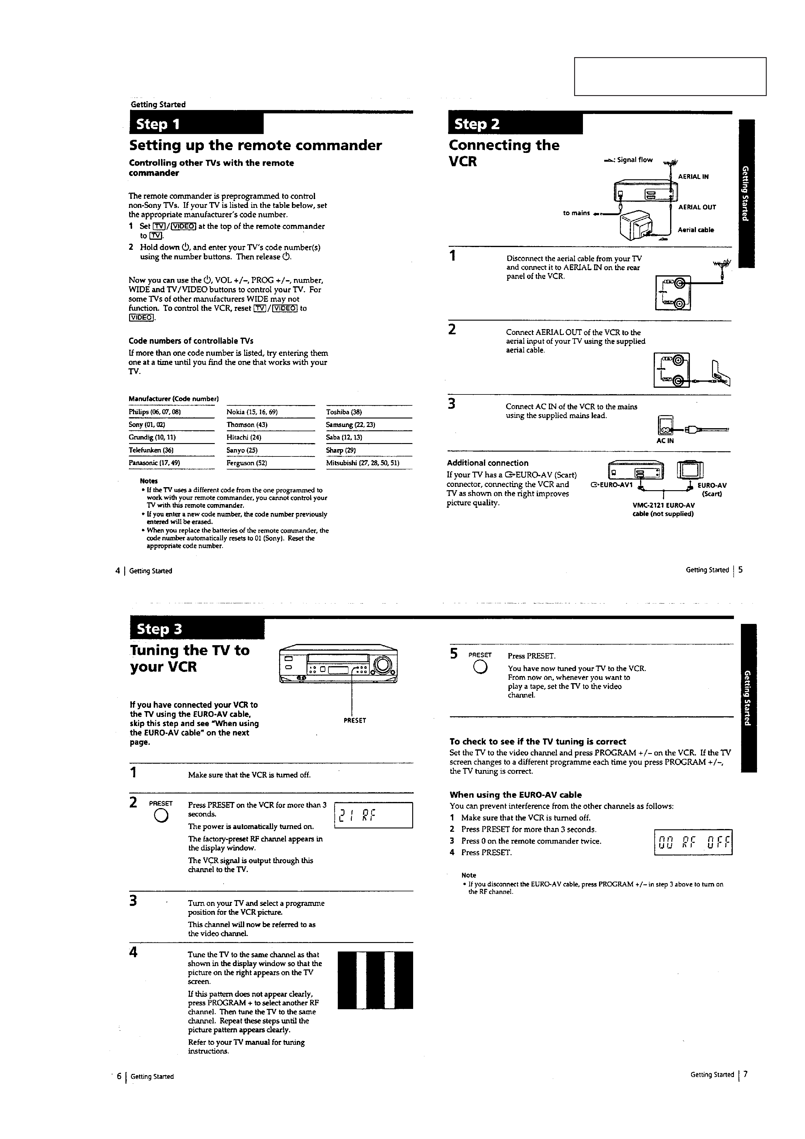
This section is extracted from
SLV-E280UX instruction manual.
SLV-E120AE/E220AE/UY/VP1/VP2/E270CP/VC1/VC2/E280CP/UX/VC1/VC2
