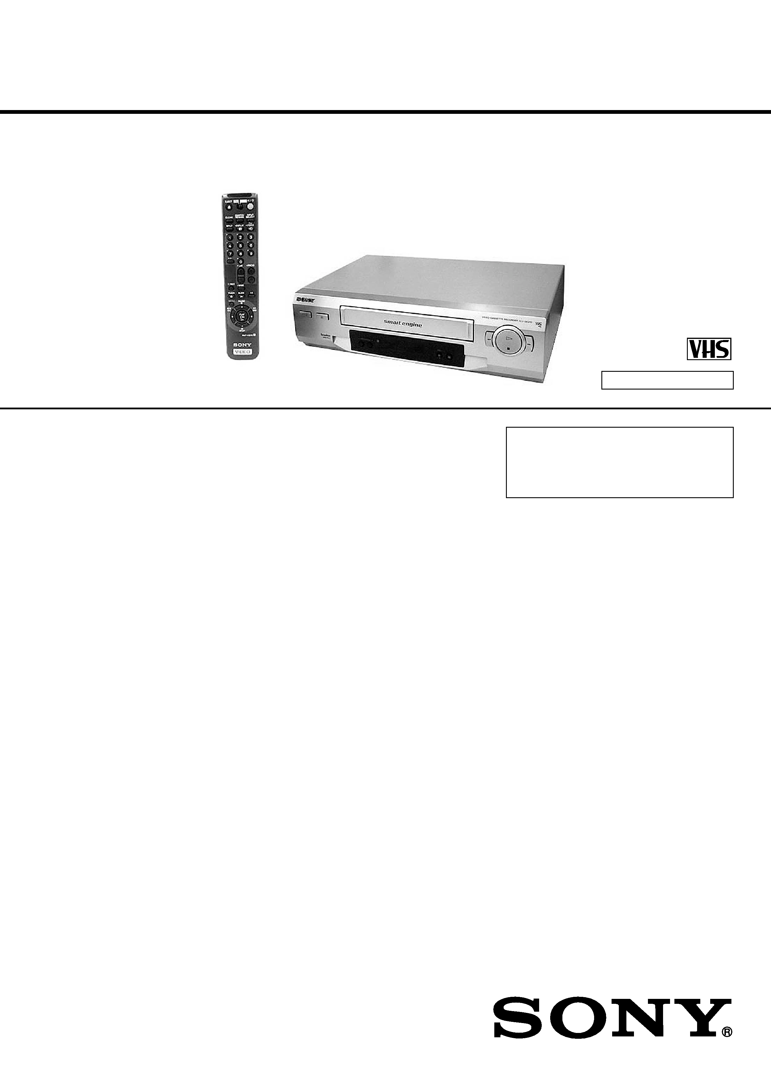
Photo: SLV-SE210
SLV-SE210B/SE210D/SE210G/
SX110A/SX110B
RMT-V257D/V257E
SERVICE MANUAL
France Model
SLV-SE210B/SX110B
Italy Model
Germany Model
North Europe Model
SLV-SE210D/SX110A
UK Model
SLV-SE210G
VIDEO CASSETTE RECORDER
SPECIFICATIONS
Refer to the SERVICE MANUAL of VHS
MECHANICAL ADJUSTMENT MANUAL
VII for MECHANICAL ADJUSTMENTS.
(9-921-790-11)
TS-10 MECHANISM
System
Channel coverage
PAL (I): (SLV-SE210G)
UHF B21 to B69
PAL (B/G)
(SLV-SE210B/SE210D/SX110B/
SX110A):
VHF E2 to E12
Italiens VHF A to H
UHF E21 to E69
CATV S01 to S05, S1 to S20
HYPER S21 to S41
SECAM (L)
(SLV-SE210B/SX110B):
VHF F2 to F10
UHF F21 to F69
CATV B to Q
HYPER S21 to S41
RF output signal
(SLV-SE210G/SE210D/SX110D)
UHF channels 21 to 69
Aerial out
75-ohm asymmetrical aerial socket
Tape speed
SP: PAL
23.39 mm/s
(recording/playback)
NTSC 33.35 mm/s
(playback only)
SECAM
(SLV-SE210B/SX110B)
23.39 mm/s
(recording/playback)
MESECAM
(SLV-SE210B/SE210D/SX110B/
SX110D)
23.39 mm/s
(recording/playback)
LP: PAL (SLV-SE210G)
11.70 mm/s
(recording/playback)
NTSC (SLV-SE210G)
16.67 mm/s
(playback only)
Maximum recording/playback time
10 hrs. in LP mode (with E300 tape)
(SLV-SE210G)
5 hrs. in SP mode (with E300 tape)
Rewind time
Approx. 60 sec. (with E180 tape)
Inputs and outputs
AV1 (EURO AV)
21-pin
Video input: pin 20
Audio input: pins 2 and 6
Video output: pin 19
Audio output: pins 1 and 3
AV2 IN (SLV-SE210B/SE210D)
21-pin
Video input: pin 20
Audio input: pins 2 and 6
General
Power requirements
240 V: (SLV-SE210G)
230 V: (SLV-SE210B/SE210D/
SX110A/SX110B)
AC, 50 Hz
Power consumption
15 W
3 W (ECO. MODE is set to ON,
Standby mode)
Operating temperature
5 C to 40 C
Storage temperature
20 C to 60 C
Dimensions
Approx. 360
× 94 × 255 mm (w/h/d)
including projecting parts and controls
Mass
Approx. 2.8 kg (SLV-SE210G)
Approx. 2.6 kg (SLV-SE210B/
SE210D/SX110A/SX110B)
Supplied accessories
Remote commander (1)
R6 (size AA) batteries (2)
Aerial cable (1)
PERITEL cable (1)
(SLV-SE210B/SX110B)
Design and specifications are subject to
change without notice.

2
1.
Check the area of your repair for unsoldered or poorly-
soldered connections. Check the entire board surface for
solder splashes and bridges.
2.
Check the interboard wiring to ensure that no wires are
"pinched" or contact high-wattage resistors.
3.
Look for unauthorized replacement parts, par-ticularly
transistors, that were installed during a previous repair.
Point them out to the customer and recommend their
replacement.
4.
Look for parts which, through functioning, show obvious
signs of deterioration. Point them out to the customer and
recommend their replace-ment.
5.
Check the line cord for cracks and abrasion.
Recommend the replacement of any such line cord to the
customer.
6.
Check the B+ voltage to see it is at the values specified.
6.
Check the antenna terminals, metal trim, "metallized"
knobs, screws, and all other exposed metal parts for AC
leakage.
Check leakage as described below.
LEAKAGE TEST
The AC leakage form any exposed metal parts to earth ground
and from all exposed metal parts to any exposed metal part
having a return to chassis, must not exceed 0.5mA (500
microampers).
Leakage current can be measured by any one of three methods.
1. A commercial leakage tester, such as Simpson 229 or RCA
WT-540A. Follow the manufactures' instructions to use these
instruments.
2. A battery operated AC milliammerter. The Data Precision
245 digital multimeter is suitable for this job.
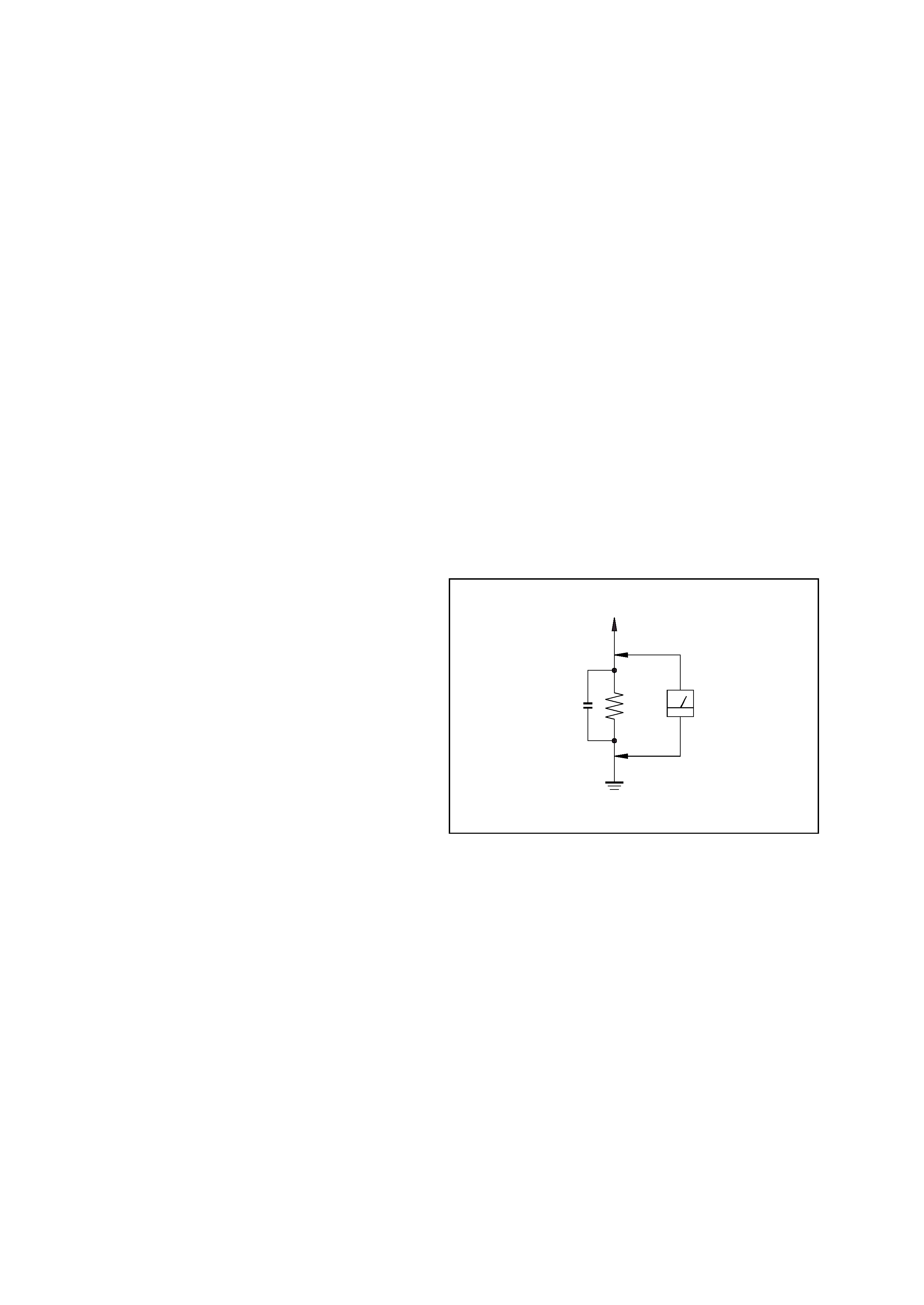
3. Measuring the voltage drop across a resistor by means of a
VOM or battery-operated AC voltmeter. The "limit"
indication is 0.75V, so analog meters must have an accurate
lowvoltage scale. The Simpson 250 and Sanwa SH-63Trd are
examples of a passive VOM that is suitable. Nearly all battery
operated digital multimeters that have a 2V AC range are
suitable. (See Fig. A)
SAFETY CHECK-OUT
After correcting the original service problem, perform the following
safety checks before releasing the set to the customer.
SAFETY-RELATED COMPONENT WARNING!!
COMPONENTS IDENTIFIED BY MARK ! OR DOTTED LINE
WITH MARK ! ON THE SCHEMATIC DIAGRAMS AND IN THE
PARTS LIST ARE CRITICAL TO SAFE OPERATION. REPLACE
THESE COMPONENTS WITH SONY PARTS WHOSE PART
NUMBERS APPEAR AS SHOWN IN THIS MANUAL OR IN
SUPPLEMENTS PUB-LISHED BY SONY.
To Exposed Metal
Parts on Set
0.15
µF
1.5 k
AC
Voltmeter
(0.75 V)
Earth Ground
Fig. A. Using an AC voltmeter to check AC leakage.

3
TABLE OF CONTENTS
SERVICE NOTE
1.
Mode Switch (Program Switch) Assembly Point ............. 4
2.
How to eject the cassette tape
(If the unit does not operate on condition that tape is
inserted into housing ass'y) ............................................... 4
3.
EEPROM Initialization and Discharging the Backup
Capacitor ............................................................................5
3-1.
NV-RAM (EEPROM) Initialization Clear the EEPROM
Using the TEST Button on the JIG Remote Controller......5
3-2.
NV-RAM (EEPROM) Initialization Clear the EEPROM
without Using the TEST Button on the JIG Remote
Controller............................................................................5
3-3.
MICOM RESET (Backup Release) ...................................5
4.
How to troubleshoot ......................................................... 6
1.
GENERAL
Getting Started
Index of parts and controls ....................................................1-1
Step 1: Unpacking .................................................................1-2
Step 2: Setting up the remote commander.............................1-2
Step 3: Connecting the VCR .................................................1-3
Step 4: Setting up the VCR with the Auto Set Up function ..1-3
Selecting a language..............................................................1-4
Presetting channels ................................................................1-4
Changing/disabling programme positions.............................1-5
Setting the clock ....................................................................1-6
Basic Operations
Playing a tape ........................................................................1-6
Recording TV programmes ...................................................1-7
Recording TV programmes using
the VIDEO Plus+ system .................................................1-8
Setting the timer manually ....................................................1-9
Additional Operations
Playing/searching at various speeds ......................................1-9
Setting the recording duration time .....................................1-10
Checking/changing/cancelling timer settings......................1-10
Adjusting the picture ...........................................................1-10
Changing menu options.......................................................1-11
Editing with another VCR...................................................1-11
Additional Information
Troubleshooting...................................................................1-12
2.
DISASSEMBLY
2-1.
Cabinet Top ................................................................... 2-1
2-2.
Cover Bottom ................................................................ 2-1
2-3.
Ass'y-Panel Front .......................................................... 2-2
2-4.
Ass'y MAIN-PCB, DECK ............................................ 2-3
2-5.
Internal Views ............................................................... 2-4
3.
PRINTED WIRING BOARDS
3-1.
Main PCB ...................................................................... 3-1
4.
SCHEMATIC DIAGRAMS
Block Identification of Main PCB ............................................ 4-1
4-1.
S.M.P.S. ........................................................................ 4-3
4-2.
Power ............................................................................ 4-5
4-3.
System Control/Servo ................................................... 4-7
4-4.
Audio/Video .................................................................. 4-9
4-5.
TM-Block .....................................................................4-11
4-6.
OSD (VPS/PDC) ......................................................... 4-13
4-7
SECAM (SLV-SE210B/SX110B model) .....................4-15
4-8.
Input-Output (2 Scart Jack) ......................................... 4-17
4-9.
Input-Output (1 Scart Jack) ......................................... 4-19
5.
ALIGNMENT AND ADJUSTMENT
5-1.
Reference .......................................................................5-1
5-1-1 Location of adjustment button of remote control .......... 5-1
5-1-2. Test point location for adjustment mode setting ........... 5-2
5-2.
Mechanical Adjustment ................................................ 5-3
5-2-1. The number and position of test point .......................... 5-3
5-2-2. ACE Head Position (X-Point) Adjustment ................... 5-3
5-3.
Head Switching Point Adjustment ................................ 5-4
5-4.
NVRAM Option Setting ............................................... 5-4
6.
REPAIR PARTS LIST
6-1.
Exploded Views ............................................................ 6-1
6-1-1. Instrument Assembly .................................................... 6-1
6-1-2. Mechanical Parts (Top Side) ......................................... 6-2
6-1-3. Mechanical Parts (Bottom Side) ................................... 6-3
6-2.
Electrical Parts List ....................................................... 6-4

4
SERVICE NOTE
1. MODE SWITCH (PROGRAM SWITCH) ASSEMBLY POINT
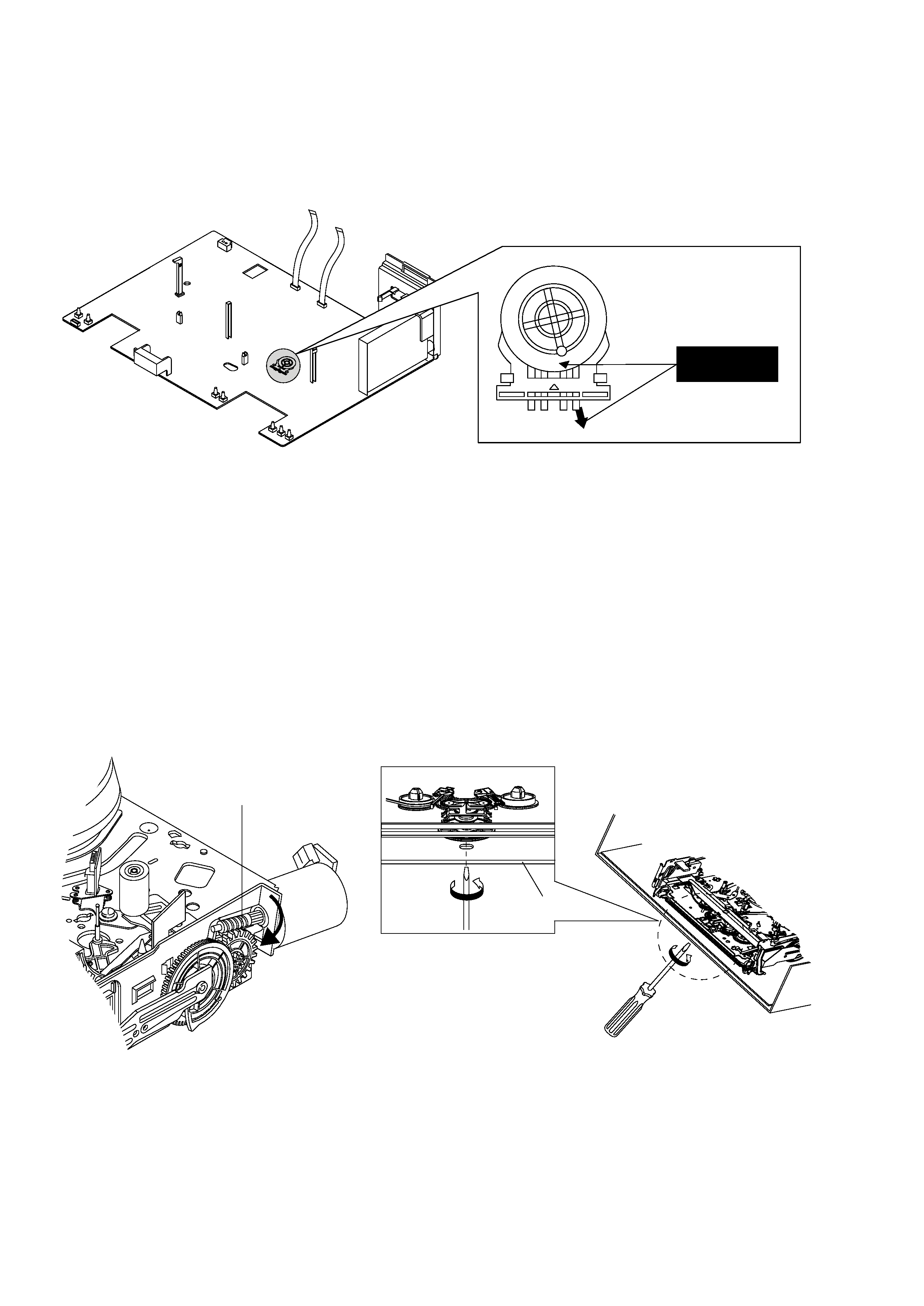
1) When installing the ass'y deck on the Main PCB, be sure to align the assembly point of mode switch.
ASSEMBLY POINT
(ALIGN TWO ARROWS)
Fig. 1
2. HOW TO EJECT THE CASSETTE TAPE
(If the unit does not operate on condition that tape is inserted into housing ass'y)
1) Turn the Gear Worm OE clockwise in the direction of arrow with screw driver. (See Fig. 2)
(Other method ; Remove the screw of Motor Load Ass'y, Separate the Motor Load Ass'y)
2) When Slider S, T are approached in the position of unloading, rotate holder Clutch counterclockwise after inserting screw driver in the
hole of frame's bottom in order to wind the unwiunded tape. (Refer to Fig. 3)
(If you rotate Gear Worm OE continuously when tape is in state of unwinding, you may cause a tape contamination by grease and
Fig. 2
Fig. 3
OE GEAR WORM
FRAME

5
3. EEPROM INITIALIZATION AND DISCHARGING THE BACKUP CAPACITOR
3-1. NV-RAM (EEPROM) Initialization Clear the EEPROM Using the TEST Button on the JIG Remote Controller
1) Plug the VCR into the mains.
Switch on the VCR by pressing (ON/STANDBY) on the remote controller.
2) Press (TEST) button on the JIG remote controller and released.
3) Within 2 seconds, press the (CLEAR) button on the remote controller.
Result:
The EEPROM will be cleared.
4) During the clearing, the "TEST" indication flashes on the front of the VCR.
The process will finish after a few seconds.(2-3 seconds)
5) After exiting the display "TEST" to normal display.
6) Press the (ON/STANDBY) button to switch off the VCR.
7) Disconnect the power supply the VCR.
It is important that you make sure ;
Do not plug the VCR into the mains after clearing EEPROM to ensure that Auto set up procedure works correctry for end users.
3-2. NV-RAM (EEPROM) Initialization Clear the EEPROM without Using the TEST Button on the JIG Remote Controller
1) Plug the VCR into the mains.
Switch on the VCR by pressing (ON/STANDBY) on the remote controller.
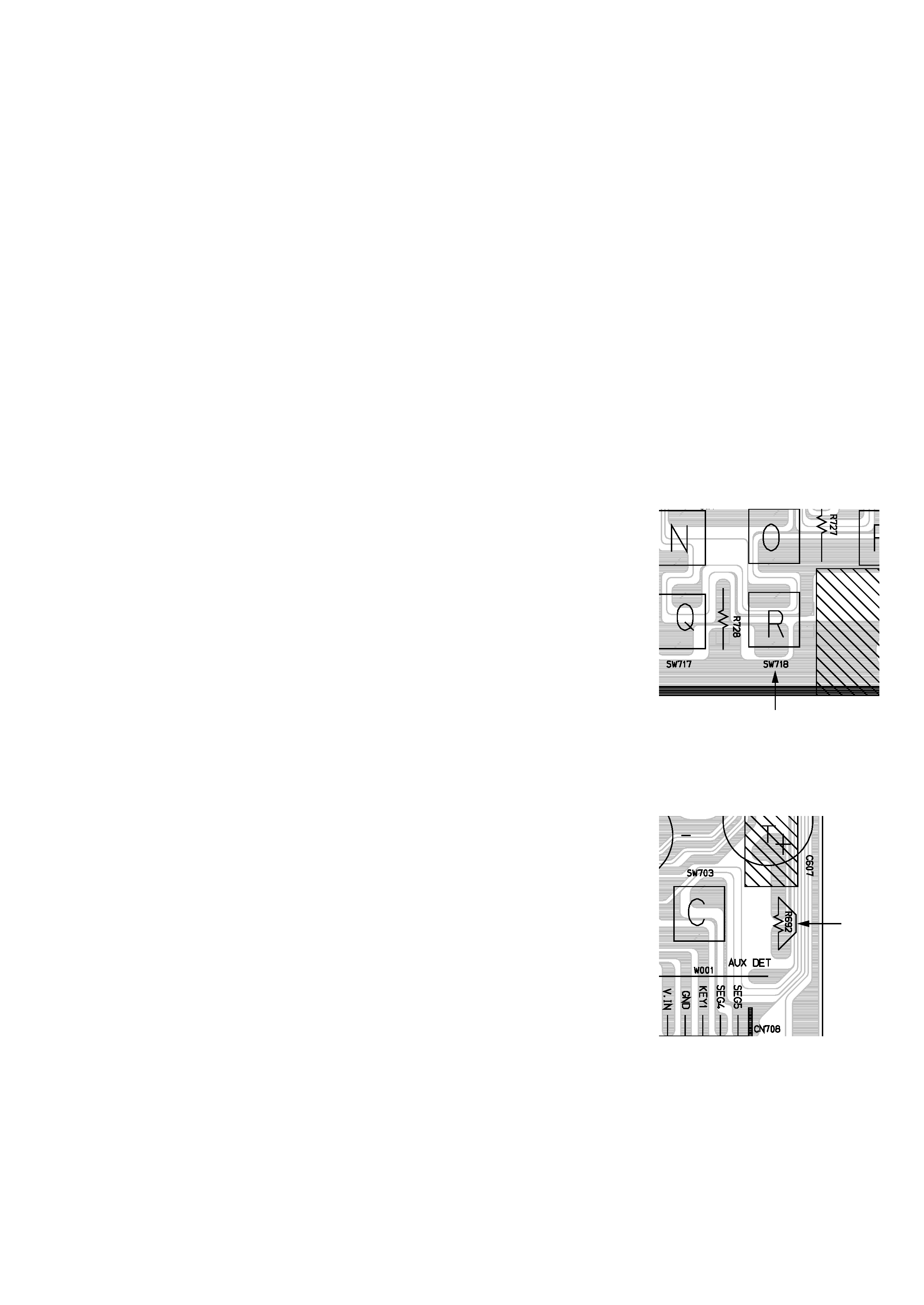
2) Press the TACT switch (SW718) on the main PCB and released.
3) Within 2 seconds, press the (CLEAR) button on the remote controller.
Result:
The EEPROM will be cleared.
4) During the clearing, the "TEST" indication flashes on the front of the VCR.
The process will finish after a few seconds.(2-3 seconds)
5) After exiting the display "TEST" to normal display.
6) Press the (ON/STANDBY) button to switch off the VCR.
7) Disconnect the power supply the VCR.
It is important that you make sure ;
Do not plug the VCR into the mains after clearing EEPROM to ensure that Auto set up procedure works correctry for end users.
3-3. MICOM RESET (Backup Release)
The automatic adjustment cannot be executed unless the backup battery is discharged even if the
memory is initialized.
Release the backup power as follows only when the adjustment is going to be mode in an ealier
time after the power is turned off.
1) Open the Top cabinet.
2) Short the R692 to TU Shield GND for a few seconds. (1 or 2 seconds)
3) Now the VCR all cleared EEPROM and reseted MICOM same as factory pre-set.
R692
SW718
