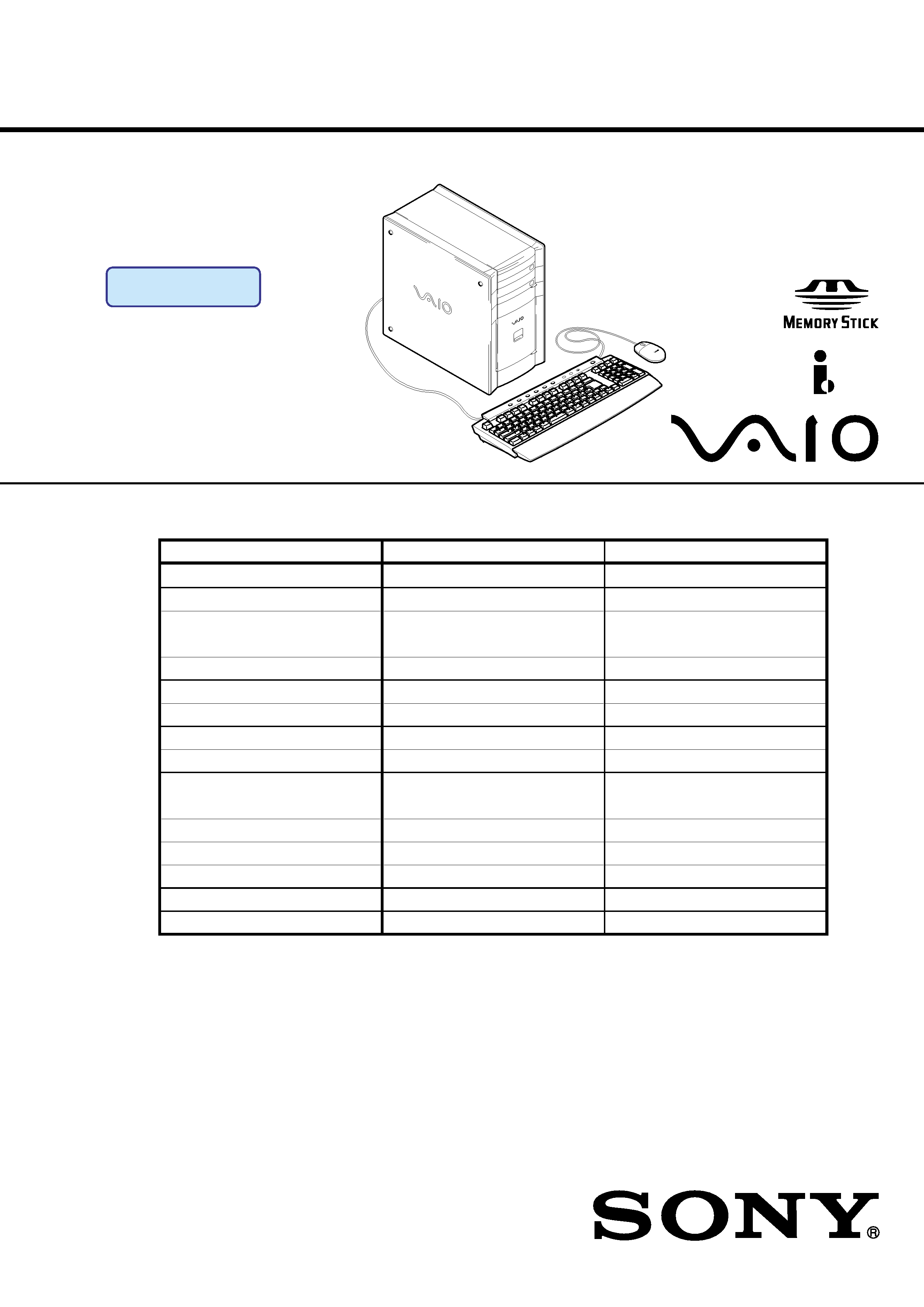
SERVICE MANUAL
PERSONAL COMPUTER VAIO
For American Area
Mexican Model
Specifications
S400
9-874-334-02
Lineup: PCV-RX64M
PCV-RX65M
PCV-RX6_M Series
Model-name
PCV-RX65M
PCV-RX64M
CPU
P4 1.8GHz
P4 1.6GHz
M/B
(AN)
(AN)
Memory
std/max
512MB/1024MB
256MB/1024MB
Slot 1
512MB
256MB
Slot 2
None
None
HDD
Bay 1
80GB
60GB
Bay 2
-
-
Opt.Device
Upper
DVD-RW
DVD-ROM
Lower
CD-ROM
CD-RW
Expansion Card
(Top)
Slot4 (AGP)
VGA Card
VGA Card
Slot3 (PCI)
-
-
Slot2 (PCI)
-
-
(Bottom) Slot1 (PCI)
Modem
Modem
MemoryStick
aa
OS
Win XP
Win XP
Ver 2-2004A
Revision History

2
PCV-RX6_ M Series (AM)
Confidential
CAUTION
Danger of explosion if battery is incorrectly replaced.
Replace only with the same or equivalent type
recommended by the manufacturer.
Dispose of used batteries according
to the manufacturer's instructions.

3
PCV-RX6_ M Series (AM)
Confidential
TABLE OF CONTENTS
1.
OPERATION ...........................................................
1-1
2.
DISASSEMBLY
2-1.
Flow Chart ................................................................
2-1
2-2.
Top Panel Section ....................................................
2-2
2-3.
Left Panel Section ....................................................
2-2
2-4.
DVD-ROM, DVD-RW, CD-RW, CD-ROM ............
2-3
2-5.
Power Unit ...............................................................
2-4
2-6.
HDD .........................................................................
2-4
2-7.
PCI Slot Panel ..........................................................
2-5
2-8.
VGA Card ................................................................
2-5
2-9.
Modem Card ............................................................
2-6
2-10.
Panel Ass'y (Upper) (For 2 Bay) .............................
2-6
2-11.
Panel Ass'y (Lower) (U) ..........................................
2-7
2-12.
Right Panel ...............................................................
2-7
2-13.
CNX-138 Board .......................................................
2-8
2-14.
SWX-66 Board ........................................................
2-8
2-15.
FDD ..........................................................................
2-9
2-16.
CNX-169 Board .......................................................
2-9
2-17.
Memory (DDR) ........................................................ 2-10
2-18.
CPU .......................................................................... 2-10
CPU Installation ....................................................... 2-11
2-19.
Mother Board ........................................................... 2-12
3.
PROGRAMS FOR SERVICE
3-1.
General .....................................................................
3-1
3-2.
PC-Doctor Starting Method .....................................
3-1
3-3.
intel815E-B Video Diag Starting Method ...............
3-1
4.
SERVICE INFORMATION
4-1.
Jumper Setting on Hard Disk Drive ........................
4-1
5.
FRAME HARNESS
5-1.
Connector List
1.
Mother Board (AN) .................................................
5-1
5-2.
Frame Harness Diagram and Jumper Setting
of Mother Board ......................................................
5-3
6.
REPAIR PARTS LIST
6-1.
Exploded Views and Parts List
(Mother Board (AN) Assy) ......................................
6-1
6-2.
Accessories and Parts List .......................................
6-4
History of the changes is shown as the "Revision
History" at the end of this data.

2-1
Confidential
PCV-RX6_ M Series (AM)
SECTION 2
DISASSEMBLY
2-1.
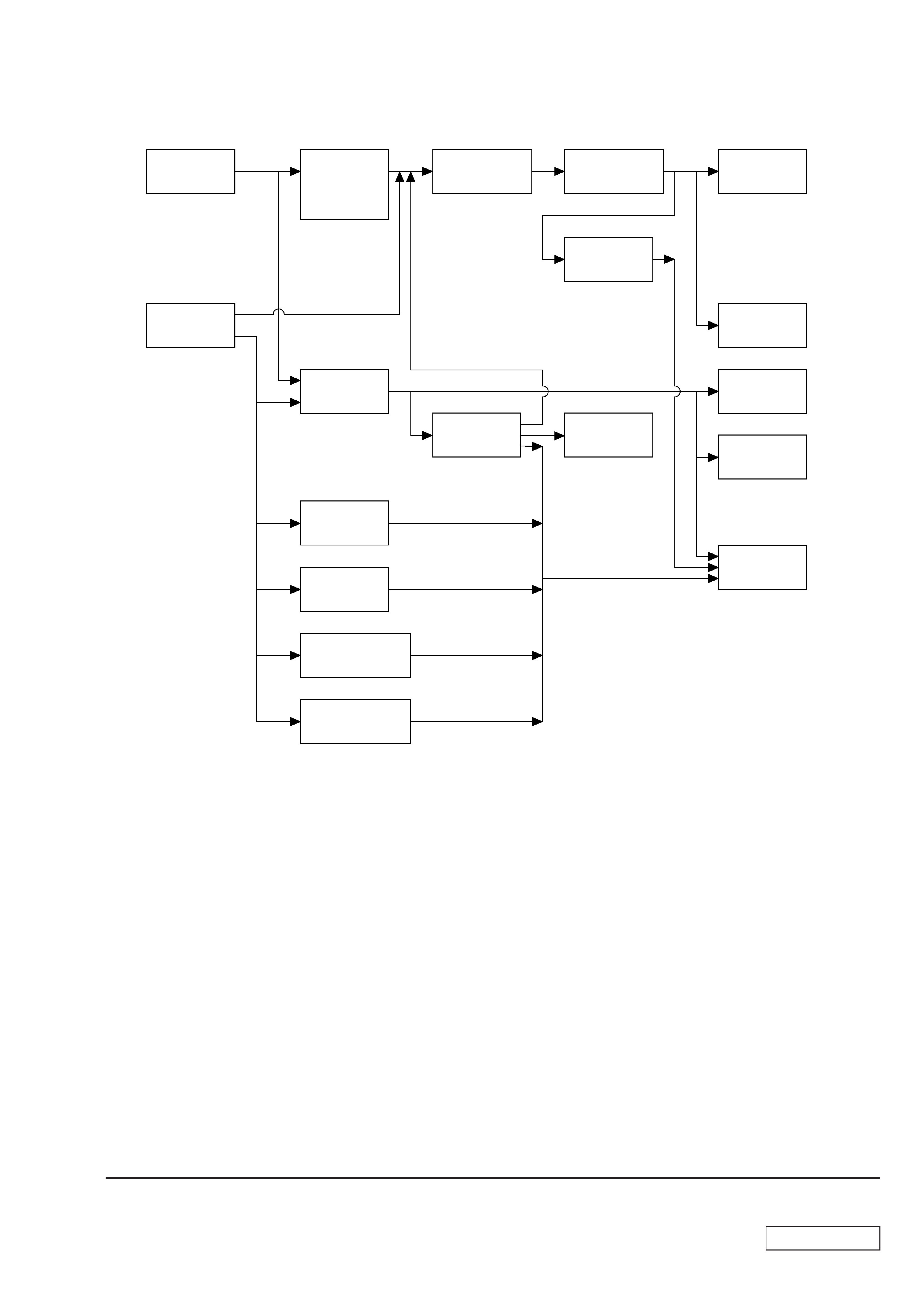
FLOW CHART
·
Ps-s denotes the page concerned.
·
HDD has a low resistance to vibration, requiring careful handling.
TOP PANEL
SECTION
P2-2
LEFT PANEL
SECTION
P2-2
DVD-ROM,
DVD-RW,
CD-RW
CD-ROM
P2-3
PANEL ASS'Y
(UPPER)
(FOR 2 BAY)
P2-6
PANEL ASS'Y
(LOWER) (U)
P2-7
RIGHT
PANEL
P2-7
SWX-66
BOARD
P2-8
P2-10
MOTHER
BOARD
P2-12
POWER
UNIT
P2-4
PCI SLOT
PANEL
P2-5
VGA CARD
P2-5
P2-6
HDD
P2-4
FDD
P2-9
CPU
P2-10
MODEM CARD
CNX-138
BOARD
P2-8
CNX-169
BOARD
P2-9
MEMORY

2-2
Confidential
PCV-RX6_ M Series (AM)
2-3.
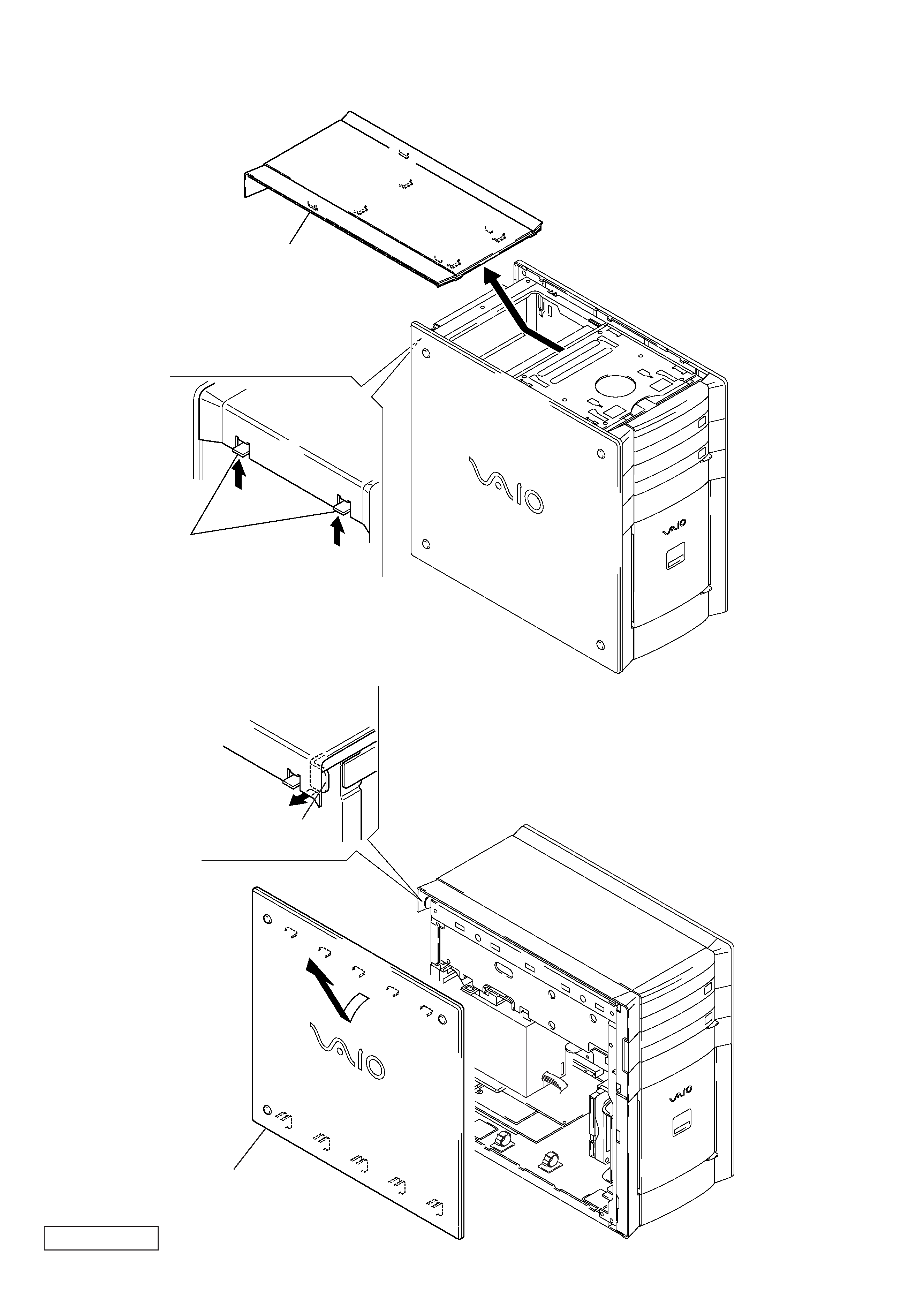
LEFT PANEL SECTION
2-2.
TOP PANEL SECTION
2
Remove the top panel section
in the direction of arrow A.
A
1
two claws
A
2
Remove the left panel section
in the direction of arrow A.
1
Pull thelever.
