1
Ver 1.2 2004. 03
Sony Corporation
Personal Audio Company
Published by Sony Engineering Corporation
9-924-998-13
2004C04-1
© 2004. 03
1
Notes on Chip Component Replacement
·Never reuse a disconnected chip component.
· Notice that the minus side of a tantalum capacitor may be
damaged by heat.
SERVICE MANUAL
US Model
Canadian Model
AEP Model
UK Model
E Model
MDR-IF5000
CORDLESS STEREO HEADPHONES
SPECIFICATIONS
Modulation System
Frequency modulation
Carrier wave frequency Right channel 2.8 MHz
Left channel 2.3 MHz
Frequency response
12 24,000 Hz
Power requirements
Rechargeable Ni-Cd
batteries (supplied) or
R6 (size AA) batteries
(dry-cell or
rechargeable, sold
separately)
Mass
Approx. 280 g
(including the
supplied rechargeable
Ni-Cd batteries)
Design and specifications are subject to
change without notice.
· MDR-IF5000 is the component model block one in
MDR-DS5000.
COMPONENT MODEL NAME FOR MDR-DS5000
DIGITAL SURROUND PROCESSOR
DP-IF5000
CORDLESS STEREO HEADPHONES
MDR-IF5000
2
SECTION 1
GENERAL
This section is extracted
from instruction manual.
3
4
SECTION 2
DISASSEMBLY
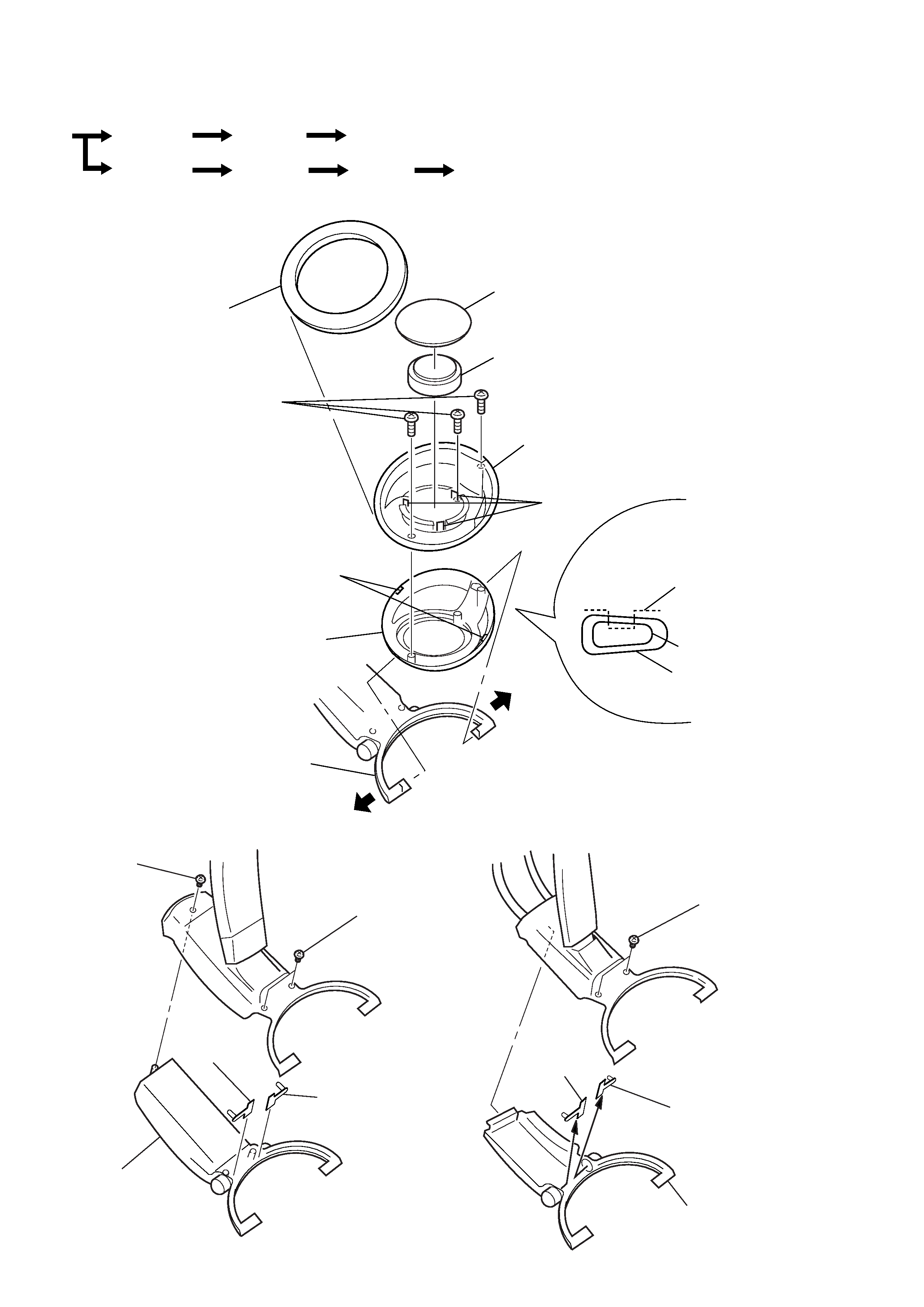
1 pad (outer), ear
2 pad (inner), ear
4 driver assy
7 plate, front
3 claws
5 P 2.6X6
6 claws
8 frame assy
9 hanger
plate, front
hanger
frame assy
spread
spread
Set
Frame assy
Frame assy
Hanger (L)
Hanger (R)
Band Assy, Head
Band Assy, Head
RX board
2 P 2.6X6
1 P 2.6X6
5 RX PD2
board (L-CH)
4 RX PD1 board (L-CH)
3 hanger (L)
1 P 2.6X6
4 RX PD2
board
(R-CH)
3 RX PD1 board (R-CH)
2 hanger (R)
2-1. FRAME ASSY
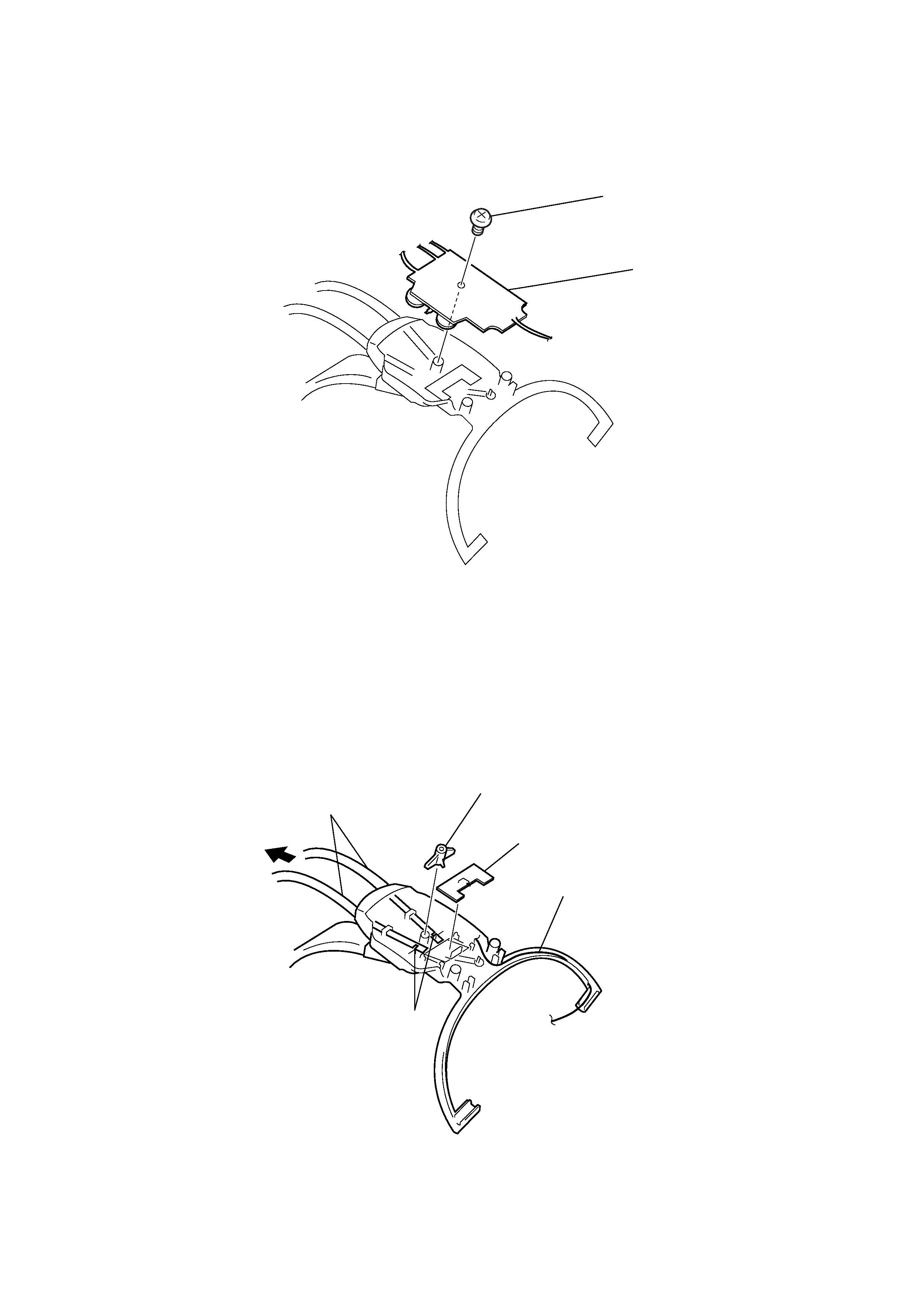
2-2. HANGER (L)
2-3. HANGER (R)
· The equipment can be removed using the following procedure.
Note : Follow the disassembly procedure in the numerical order given.
· Remove the left and right ear
pads in the same manner.
5
5 band assy, head
3 stopper, PC board
2 RX SW board
1 wire
When installing,
take care to avoid extrusion
of wire from the hanger.
4 claws
1 P 2.6X6
2 RX board
2-4. RX BOARD
2-5. BAND ASSY, HEAD