SERVICE MANUAL
MODEL
COMMANDER
DEST. CHASSIS NO.
MODEL
COMMANDER
DEST. CHASSIS NO.
MICROFILM
Please file according to model size. ...
41
CHASSIS
48 53 61
RG-2
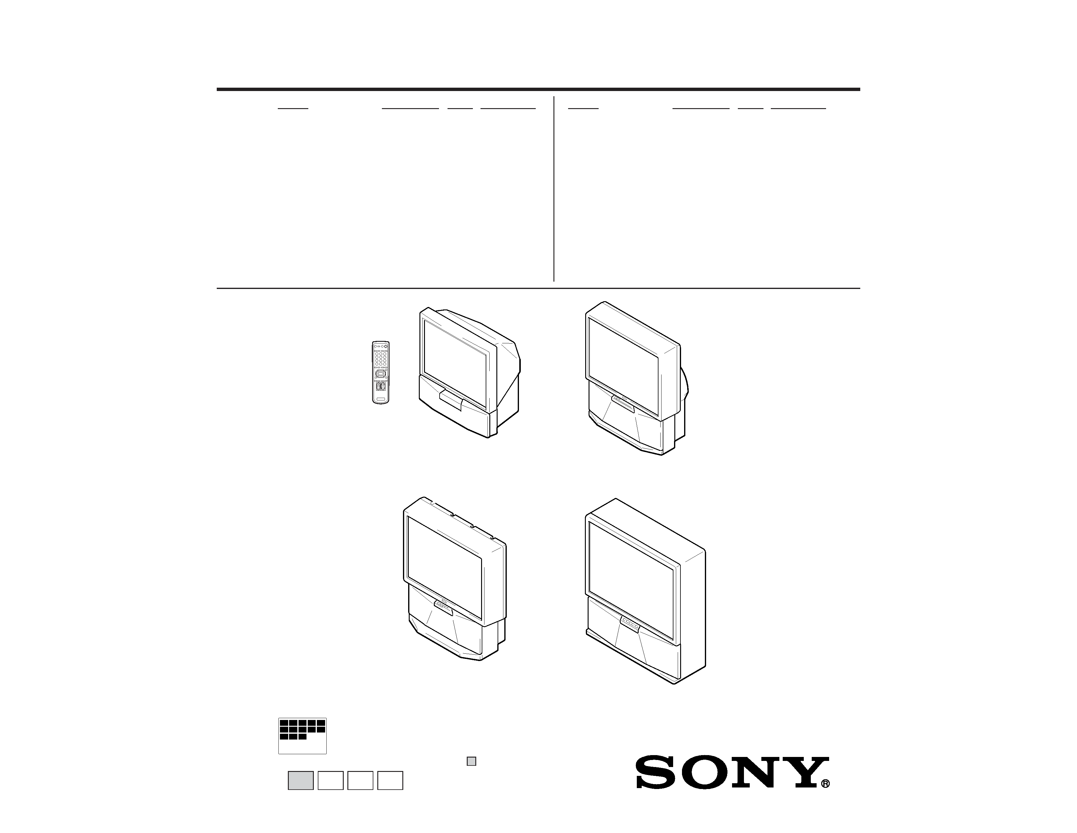
PROJECTION TV
KP-EF41HK RM-871
HK
SCC-N71A-A
KP-EF41ME RM-871
ME
SCC-N72A-A
KP-EF41MN RM-871
GE
SCC-N69A-A
KP-EF41SN RM-871
AUS
SCC-N73A-A
KP-EF48HK RM-871
HK
SCC-N71C-A
KP-EF48ME RM-871
ME
SCC-N72C-A
KP-EF48MN RM-871
GE
SCC-N69C-A
KP-EF48SN RM-871
AUS
SCC-N73C-A
KP-EF53HK RM-871
HK
SCC-N71B-A
KP-EF53ME RM-871
ME
SCC-N72B-A
KP-EF53MN RM-871
GE
SCC-N69B-A
KP-EF53SN RM-871
AUS
SCC-N73B-A
KP-EF61HK RM-871
HK
SCC-N71D-A
KP-EF61ME RM-871
ME
SCC-N72D-A
KP-EF61MN RM-871
GE
SCC-N69D-A
KP-EF61SN RM-871
AUS
SCC-N73D-A
KP-EF41HK/EF41ME/
KP-EF41MN/EF41SN
KP-EF48HK/EF48ME/
KP-EF48MN/EF48SN
KP-EF61HK/EF61ME/
KP-EF61MN/EF61SN
KP-EF53HK/EF53ME/
KP-EF53MN/EF53SN

2
KP-EF41HK/ME/MN/SN, EF48HK/ME/MN/SN,
KP-EF53HK/ME/MN/SN, EF61HK/ME/MN/SN RM-871
Projection system
3 picture tubes, 3 lenses, horizontal in-
line system
Picture tube
7 inch high-brightness monochrome
tubes (6.3 raster size), with optical
coupling and liquidcooling system
Projection lenses High performance, large-diameter
hybrid lens
Screen size
41 inches (KP-EF41)
48 inches (KP-EF48)
53 inches (KP-EF53)
61 inches (KP-EF61)
Television system
B/G, I, D/K, M
Color system
PAL, PAL 60, SECAM, NTSC4.43,
NTSC3.58
Channel coverage
B/G
VHF: E2 to E12
UHF: E21 to E69
CATV: S01 to S03, S1 to S41
I
UHF: B21 to B68
CATV: S01 to S03, S1 to S41
D/K
VHF: C1 to C12, R1 to R12
UHF: C13 to C57, R21 to R60
CATV: Z1 to Z39, S01 to S03, S1 to S41
M
VHF: A2 to A13
UHF: A14 to A79
CATV: A-8 to A-2, A to W+4,
W+6 to W+84
Stereo system
NICAM stereo B/G, I, D/K
A2 stereo (German) B/G
Antenna
75 ohm external antenna terminal
Audio output (Speaker)
15 W
× 2
Number of terminals
Video
Input: 4, Output: 1
phono jacks, 1 Vp-p, 75 ohms
Audio
Input: 5, Output: 1, VARIABLE output:
1, phono jacks, 500 mVrms
S video
Input: 2,
Y: 1 Vp-p, 75 ohms, unbalanced, sync
negative,
C: 0.286 Vp-p, 75 ohms
Component video
Input: 1, phono jacks
Y: 1.0 Vp-p, 75 ohms, sync negative
CB/B-Y: 0.7 Vp-p, 75 ohms
CR/R-Y: 0.7 Vp-p, 75 ohms
Audio: 500 mVrms
Headphone
Output: 1, minijack
Power requirement
110 240 V AC, 50/60 Hz
Power consumption
160 W
Dimensions (w/h/d)
948
× 992 × 511 mm (KP-EF41)
1106
× 1336 × 558 mm (KP-EF48)
1218
× 1413 × 602 mm (KP-EF53)
1338
× 1520 × 655 mm (KP-EF61)
Mass
Approx. 43 kg (KP-EF41)
Approx. 66 kg (KP-EF48)
Approx. 70 kg (KP-EF53)
Approx. 124 kg (KP-EF61)
Supplied accessories
Remote commander RM-871 (1)
Size R6 (AA) battery (2)
Optional accessory
AV rack SU-EF41 (KP-EF41),
SU-EF4853 (KP-EF48/EF53)
Design and specifications are subject to change without
notice.
CAUTION
SHORT CIRCUIT THE ANODE OF HTE PICTURE TUBE
AND THE ANODE CAP TO THE METAL CHASSIS, CRT
SHIELD, OR CARBON PAINTED ON THE CRT, AFTER
REMOVING THE ANODE.
SAFETY-RELATED COMPONENT WARNING!!
COMPONENTS IDENTIFIED BY SHADING AND MARK
! ON THE SCHEMATIC DIAGRAMS, EXPLODED
VIEWS AND IN THE PARTS LIST ARE CRITICAL TO
SAFE OPERATION. REPLACE THESE COMPONENTS
WITH SONY PARTS WHOSE PART NUMBERS AP-
PEAR AS SHOWN IN THIS MANUAL OR IN SUPPLE-
MENTS PUBLISHED BY SONY.
SPECIFICATIONS

3
KP-EF41HK/ME/MN/SN, EF48HK/ME/MN/SN,
KP-EF53HK/ME/MN/SN, EF61HK/ME/MN/SN RM-871
1. GENERAL .................................................................
4
2. DISASSEMBLY
2-1.
Rear Board Removal .........................................
19
2-2.
Main Bracket Section Removal ........................
20
2-3.
Service Position .................................................
21
2-4.
H1 Board, H2 Board and Resistor
(High Voltage) Removal ...................................
22
2-5.
Beznet Section Removal ...................................
24
2-6.
G Board Removal ...............................................
26
2-7.
P1 Board and V2 Board Removal ......................
26
2-8.
UG Baord, AG Baord ans S Board Removal ....
26
2-9.
High-Voltage Cable Installation and Removal ..
27
2-10. Mechasel Assy Removal ....................................
27
2-11. Chassis Block Removal ......................................
28
(1)
H1, H2 Boards and Resistor Removal ..............
28
(2)
Main Bracket Removal ......................................
29
(3)
Chassis Block Removal .....................................
30
3. SET-UP ADJUSTMENTS
3-1.
Screen Voltage Adjustment
(Rough Alignment) ...........................................
31
3-2.
Focus Adjustment ..............................................
31
3-3.
Screen (G2) Adjustment ....................................
31
3-4.
Deflection Yoke Tilt Adjustment ......................
31
3-5.
2-Pole Magnet Adjustment ................................
32
3-6.
4-Pole Magnet Adjustment ................................
32
3-7.
Defocus Adjustment (Blue) ...............................
32
3-8.
Green and Red Focus Adjustment .....................
32
3-8-1. Green and Red Lens Focus Adjustment .......
32
3-8-2. Green and Red Electrical Focus
Adjustment ....................................................
32
4. SAFETY RELATED ADJUSTMENT
4-1.
HV Hold Down Adjustment .............................
33
5. CIRCUIT ADJUSTMENTS ................................
34
5-1.
Adjustments with Commander .........................
34
5-2.
Adjustment Method ...........................................
35
5-3.
Adjustment After IC1001 and IC1702
Replacement .......................................................
35
5-4.
Registration (Convergence)Adjustment
Method ................................................................
42
5-5.
Auto Convergence Adjustment ..........................
47
5-6.
White Balance Adjustment ................................
48
5-7.
Text Position Adjustment ...................................
48
5-8.
Picture Quality Adjustments .............................
48
TABLE OF CONTENTS
6. DIAGRAMS
6-1.
Block Diagrams ..................................................
49
6-2.
Frame Schematic Diagram .................................
62
6-3.
Circuit Boards Location .....................................
62
6-4.
Schematic Diagrams and Printed Wiring
Boards .................................................................
63
(1)
Schematic Diagram of AG (1/3) Board .............
67
(2)
Schematic Diagram of AG (2/3) Board ............
71
(3)
Schematic Diagrams of AG (3/3), CB, CG and
CR Boards .........................................................
75
(4)
Schematic Diagram of E Board .........................
79
(5)
Schematic Diagram of D Board ........................
89
(6)
Schematic Diagram of P1 and V2 Boards .........
93
(7)
Schematic Diagrams of H1, H2, S,
ZG and ZR Boards ............................................. 101
(8)
Schematic Diagrams of G and UG Boards ........ 104
6-5.
Semiconductors ................................................. 109
7. EXPLODED VIEWS
7-1.
Screen and Cover Block (KP-EF41) ................. 111
7-2.
Cabinet and Panel Block (KP-EF41) ................ 112
7-3.
Chassis and Picture Tube Block (KP-EF41) ..... 113
7-4.
Screen and Cover Block (KP-EF48) .................. 114
7-5.
Cabinet and Panel Block (KP-EF48) ................. 115
7-6.
Chassis and Picture Block (KP-EF48) ............... 116
7-7.
Screen and Cover Block (KP-EF53) .................. 117
7-8.
Cabinet and Panel Tube Block (KP-EF53) ........ 118
7-9.
Chassis and Picture Tube Block (KP-EF53) ..... 119
7-10. Screen Block (KP-EF61) .................................... 120
7-11. Panel and Cover Block (KP-EF61) ................... 121
7-12. Chassis and Picture Tube Block (KP-EF61) ..... 122
8. ELECTRICAL PARTS LIST ............................ 123
Section
Title
Page
Section
Title
Page

4
SECTION 1
GENERAL
The operating instructions mentioned here are partial abstracts
from the Operating Instruction Manual. The page numbers of
the Operating Instruction Manual remain as in the manual.
6-EN
Getting Started
1
L
(MONO)
R
2
3
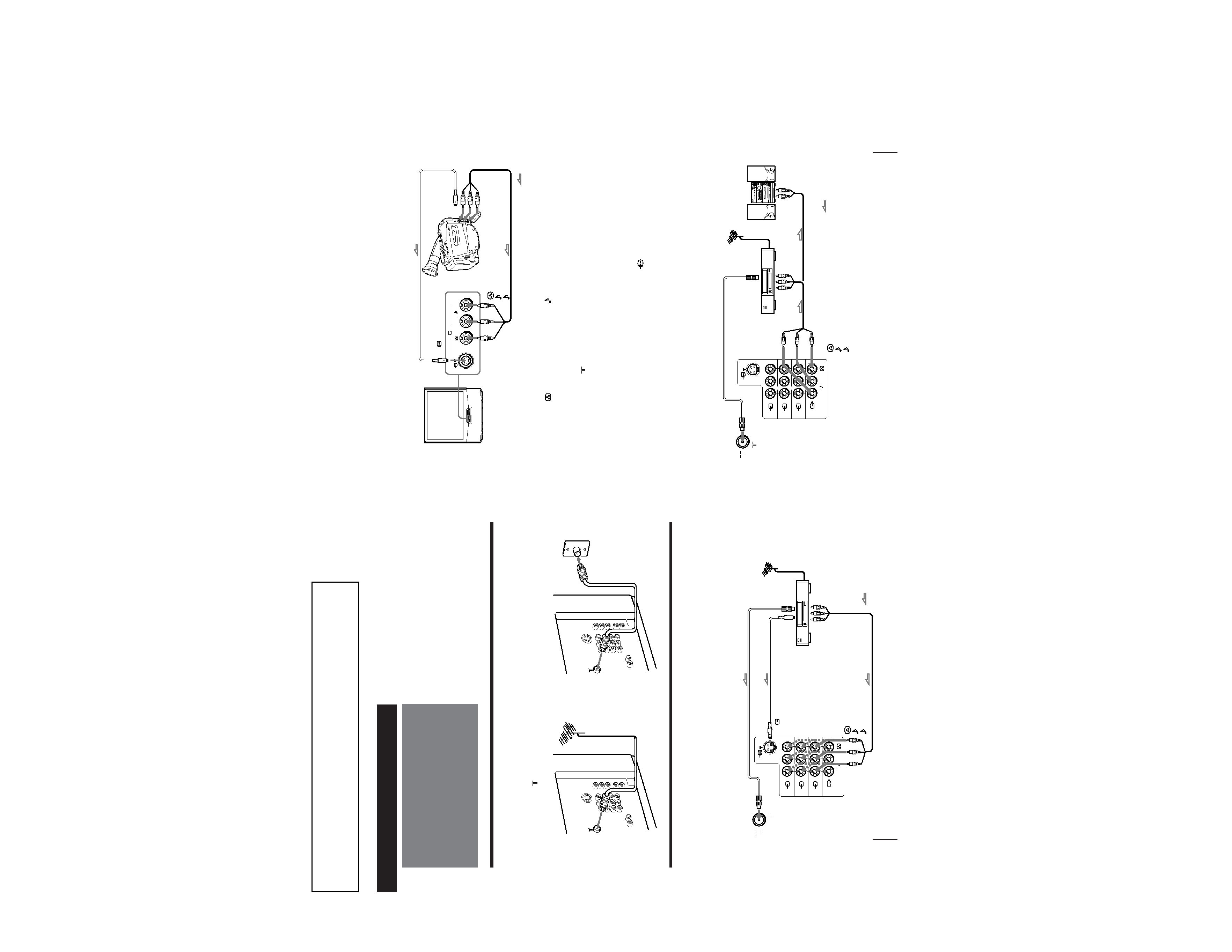
Connecting a VHF antenna or a combination VHF/UHF antenna
-- 75-ohm coaxial cable (round)
Attach an optional IEC antenna connector to the 75-ohm coaxial cable.
Plug the connector into the
(antenna) socket at the rear of the TV.
Connecting optional equipment
You can connect optional audio/video equipment to your TV such as a VCR, multi disc player, camcorder, video
game or stereo system.
Connecting video equipment using video input jacks
Connections
On a wall
Rear of TV
Rear of TV
or
Rear of TV
VCR
to
S video
output
to
antenna
output
to video and
audio outputs
: Signal flow
Getting Started
to
(antenna) socket
to ... 1, 2, or 3 (video input)
(yellow)
-L (MONO)(white)
-R (red)
to
(S video input)
7-EN
Getting Started
Camcorder
to S video output
to video and
audio outputs
: Signal flow
Rear of TV
VCR
to
antenna
output
to video and
audio inputs
Audio system
to audio
inputs
: Signal flow
or
L(MONO)
R
3
1
L
(MONO)
R
2
3
to
(S video input)
to ... 3 (video input)
(yellow)
-L (MONO)(white)
-R (red)
to
(antenna) socket
to Ú (monitor/TV output)
(yellow)
-L (MONO)(white)
-R (red)
When connecting a monaural VCR
Connect the yellow plug to
(video input) and the black plug to
-L (MONO) (audio input).
When connecting video game equipment
Connect video game equipment to the ... 3 (video input) jacks at the front or the rear of your TV.
When connecting a VCR to the
(antenna) terminal
Preset the signal output from the VCR to the program position 0.
When connecting video equipment to the ... 3 (video input) jacks at the front and the rear
Do not connect video equipment to the ... 3 (video input) jacks at the front and the rear of your TV simultaneously; otherwise the picture
will not be displayed properly on the screen.
If both S Video and video signals are input simultaneously
The S video input signal is selected. To view a video input signal, disconnect the
(S video) connection.
Note on the video input
When no signal is input, the screen becomes blue.
Connecting audio/video equipment using Ú (monitor/TV output) jacks
Front of TV

5
8-EN
Getting Started
COMPOMENT VIDEO OUT
S VIDEO OUT
LINE OUT
CB/B-Y
YCR/R-Y
R-AUDIO-L
VIDEO
CR/
R-Y
CB/
B-Y
Y
L
R
1
L
(MONO)
R
2
3
LINE OUT
R-AUDIO-L
VIDEO
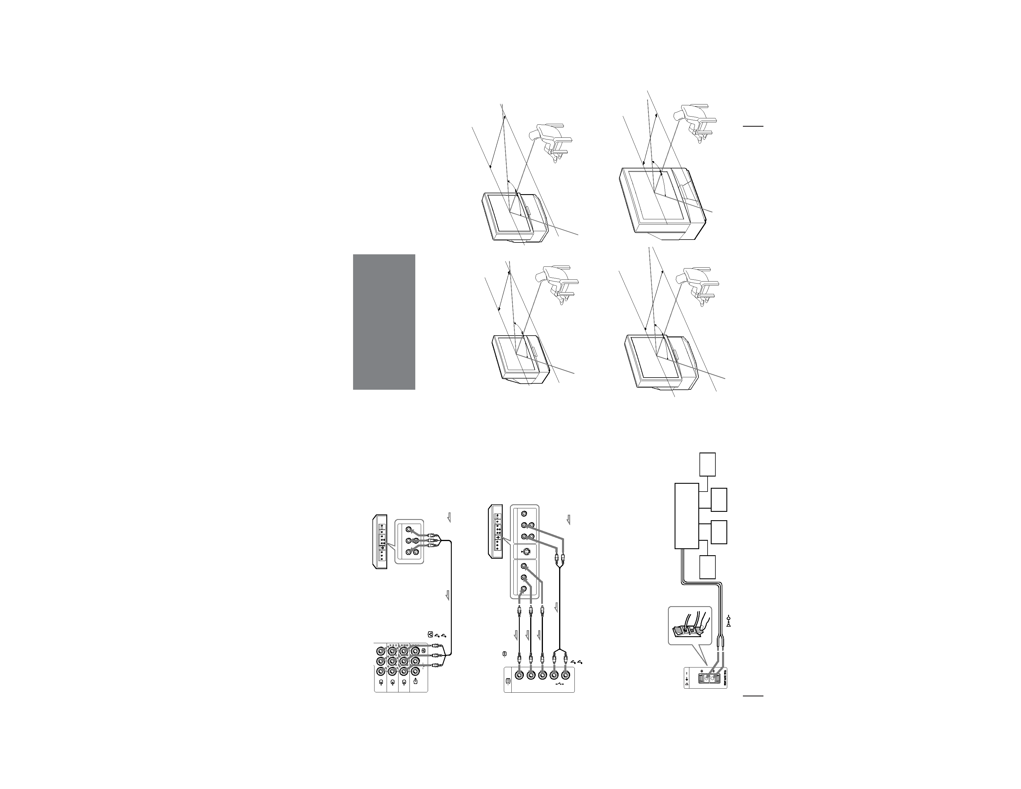
Connecting a DVD player
C
Connecting an amplifier with Dolby* Pro Logic decoder
Even though you use an amplifier with Dolby Pro Logic
decoder instead of the projection TV's audio system, you
can still use the projection TV's center speaker.
*
Manufactured under license from Dolby Laboratories
Licensing Corporation.
DOLBY, the double-D symbol a and "PRO LOGIC" are
trademarks of Dolby Laboratories Licensing Corporation.
Amplifier with Dolby Pro
Logic decoder
Rear
speaker
(L)
Rear
speaker
(R)
Front
speaker
(L)
Front
speaker
(R)
to
(center speaker
inputs)
Rear of TV
Connecting a DVD player with component video output connecors
Notes
· Since the high quality pictures on a DVD disc contain a lot of
information, picture noise may appear. In this case, adjust the
sharpness (SHARP) in the VIDEO ADJUST menu. (See page 20.)
· Connect your DVD player directly to your TV. Connecting the
DVD player through other video equipment will cause unwanted
picture noise.
Rear of TV
: Signal flow
to audio/
video
outputs
DVD player
to ... 1, 2, or 3 (video input)
(yellow)
-L (MONO)(white)
-R (red)
Rear of TV
: Signal flow
-L (white)
-R (red)
to
(component video
input) Y/CB/B-Y/CR/R-Y
to component video
output
to audio output
DVD player
9-EN
Getting Started
For the best picture quality, install the projection TV
within the areas shown below.
Optimum viewing area (Horizontal)
KP-EF41
Installing the
projection TV
KP-EF53
min 1.5m (5 ft.)
min 2.1m (7 ft.)
75°
75°
75°
75°
KP-EF48
KP-EF61
min 1.8m (6 ft.)
75°
75°
min 2.7m (9 ft.)
75°
75°
