D-T101/T401/T405
SERVICE MANUAL
FM/AM COMPACT DISC COMPACT PLAYER
MICROFILM
Model Name Using Similar Mechanism
D-265/365
CD Mechanism Type
CDM-2811CAA
Optical Pick-Up Name
DAX-11C
US Model
Canadian Model
D-T401/T405
AEP Model
UK Model
E Model
Chinese Model
Australian Model
D-T101/T401/T405
Tourist Model
D-T405
SPECIFICATIONS
-- Continued on next page --
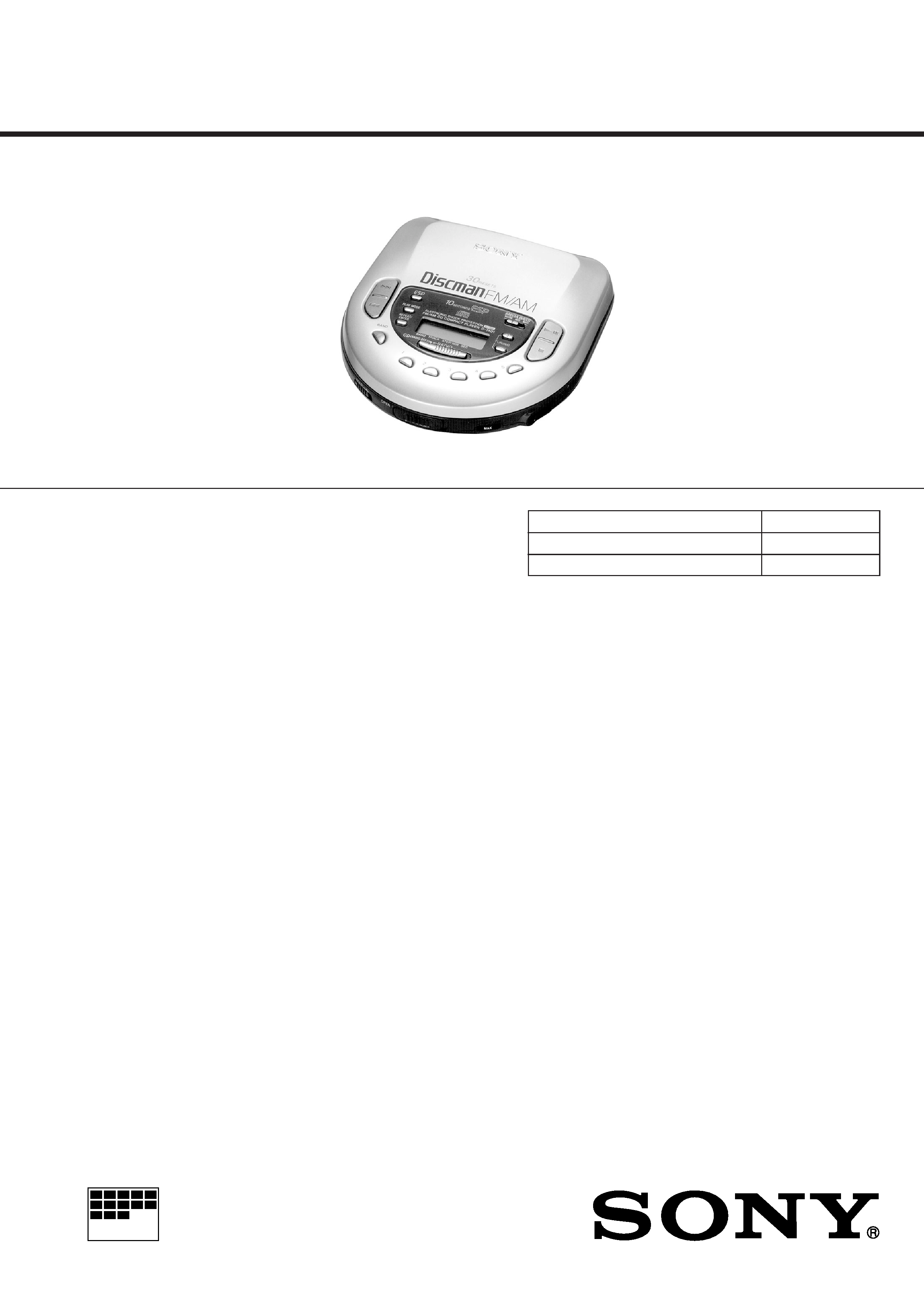
Photo : D-T401
CD player section
System
Compact disk digital audio system
Laser diode properties
Material:GaAIAs
Wavelength:
=780nm
Emission duration:Continuous
Laser output:less than 44.6uW (measured at 200mm
away from the objective lens surface)
Error correction
Sony Super Stlategy Cross Interleave Reed Solomon Code
D-A conversion
1-bit quartz time-axis control
Frequency response
20-20,000Hz
2
dB (measured by EIAJ CP-307)
Output(at 4.5V input level)
Headphones (stereo minijack)
15mW+15mW at 16ohms
Line output (stereo minijack)
Output level 0.7Vrms at 50kilohms
Recommended load impedance over 10 kilohmes
Optical digital output (optical output connector)
Output level2115dBm
Wavelength:630-690nm at peak level
Radio section
Frequency range
FM:87.5-108.0MHz
AM:531-1,602kHz
Antenna
FM:Headphones coad antenna
AM:Built-in ferrite bar antenna
Genaral
For the area code of the model you purchased,
check the upper left side of the bar code on the
package.
Power requirements
· Sony BP-DM10 Rechargeable battery:
2.4V DC,Ni-Cd,650mAh
Sony BP-DM20 Rechargeable battery:
2.4V DC,Ni-MH,1,200mAh
· Two LR6 (Size AA) batteries:3 V DC
· AC power adaptor (DC IN 4.5V jack)
US/CND/E92model:220-230V, 50/60Hz
UK model:230-240V,50Hz
EA model:110-240V,50/60Hz
AUS model:240V,50Hz
JEW/E33 model:100-240V,50/60Hz
· Sony CPM-300P mount plate for use on car
battery:4.5 V DC
Dimensions(w/h/d) (without projecting parts and
controls)
Approx.132
×34.0×135.6
(51/4×11/4×53/8in.)
Mass (without rechargeable battery)
Approx.280g (9.9oz)
Operating temperature
5
°C-35°C (41°F-95°F)
Supplied accessories
T405
For the area code of the model you purchased,
check the upper left side of the bar code on the
package.
AC power adaptor (1)
Head phones (1)
Earphones (1)
Rechargeable battery (1)
Battery case (1)
Connecting cord (phone plug
×2stereo
miniplaug) (1)
Carrying case (1)
a) Supplied with US model
b) Not supplied US model
c) Not supplied with US,CND and E92 models
d) Not supplied with JEW, AEP, UK and CEF
models
Design and specifications are subject to change
without notice
+1

-- 2 --
TABLE OF CONTENTS
SAFETY-RELATED COMPONENT WARNING!!
COMPONENTS IDENTIFIED BY MARK ! OR DOTTED LINE WITH
MARK ! ON THE SCHEMATIC DIAGRAMS AND IN THE PARTS
LIST ARE CRITICAL TO SAFE OPERATION. REPLACE THESE
COMPONENTS WITH SONY PARTS WHOSE PART NUMBERS
APPEAR AS SHOWN IN THIS MANUAL OR IN SUPPLEMENTS
PUBLISHED BY SONY.
ATTENTION AU COMPOSANT AYANT RAPPORT
À LA SÉCURITÉ!
LES COMPOSANTS IDENTIFÉS PAR UNE MARQUE ! SUR LES
DIAGRAMMES SCHÉMATIQUES ET LA LISTE DES PIÈCES SONT
CRITIQUES POUR LA SÉCURITÉ DE FONCTIONNEMENT. NE
REMPLACER CES COMPOSANTS QUE PAR DES PIÈSES SONY
DONT LES NUMÉROS SONT DONNÉS DANS CE MANUEL OU
DANS LES SUPPÉMENTS PUBLIÉS PAR SONY.
T101
Supplied accessories
AC power adaptor(1)
Earphones(1)
Connecting cord(phone plugx2 stereo miniplug)(1)
T401
AC power adaptor(1)
Headphones(1)
Earphones(1)
Connecting cord(phone plugx2 stereo miniplug)(1)
a)Supplied with US model
b)Not supplied with US model
c)Not supplied with AEP,UK and CEF models
Recommended accessories
Mount plate CPM-300P
Mount kit CPM-450PC
Mount kit CPM-300PC
Car connecting pack CPA-9
Car battery cord with car connecting pack
DCC-E26CP
Car battery cord DCC-E245
Active speaker system SRS-A21,SRS-A41,
SRS-A71
Rechargeable battery BP-DM10,BP-DM20
Connecting cord RK-G129HG
Optical digital connecting cord POC-5B
POC-10B,POC-15B,POC-5AB,POC-10AB,POC-15AB
AC power adaptor AC-E45HG
Stereo headphones MDR-35,MDR-E848
Sold in Japan only
Your dealer may not handle some of the above listed accessories.Pleaseask the dealer
for detailed information about the accessories in your country.
NOTE:
In this set, there are a former type (board suffix-12) and a
new type (board suffix-13).
In electrical adjustment, between a former type and a new
type, there is a difference of measurement point.
Flexible Circuit Board Repairing
· Keep the temperature of the soldering iron around 270
°C during
repairing.
· Do not touch the soldering iron on the same conductor of the
circuit board (within 3 times).
· Be careful not to apply force on the conductor when soldering or
unsoldering.
Notes on chip component replacement
· Never reuse a disconnected chip component.
· Notice that the minus side of a tantalum capacitor may be
damaged by heat.
NOTES ON LASER DIODE EMISSION CHECK
The laser beam on this model is concentrated so as to be focused
on the disk reflective surface by the objective lens in the optical
pick-up block. Therefore, when checking the laser diode emission,
observe from more than 30cm away from the objective lens.
1.
GENERAL ······································································ 4
2.
SERVICE NOTE ··························································· 7
3.
DISASSEMBLY
3-1.
Cabinet (Lower) ································································· 8
3-2.
Cabinet (Upper) ·································································· 8
3-3.
Tuner Board ········································································ 9
3-4.
CD Board ············································································ 9
4.
SERVICE MODE ························································ 10
5.
ELECTRICAL ADJUSTMENT ······························ 11
6.
DIAGRAMS
6-1.
Block Diagram CD Section ·········································· 16
6-2.
Block Diagram Tuner Section ······································ 19
6-3.
Printed Wiring Board Tuner Section ···························· 21
6-4.
Schematic Diagram Tuner Section ······························· 23
6-5.
IC Block Diagrams ··························································· 25
6-6.
Printed Wiring Board CD Section ······························· 26
6-7.
Schematic Diagram CD Section ··································· 29
6-8.
IC Block Diagrams ··························································· 34
6-9.
IC Pin Function ································································ 39
7.
EXPLODED VIEWS
7-1.
Cabinet Section-1 ····························································· 43
7-2.
Cabinet Section-2 ····························································· 44
7-3.
Optical Pick-up Section (CDM-2811CAA) ····················· 45
8.
ELECTRICAL PARTS LIST ··································· 46

-- 3 --
SECTION 1
GENERAL
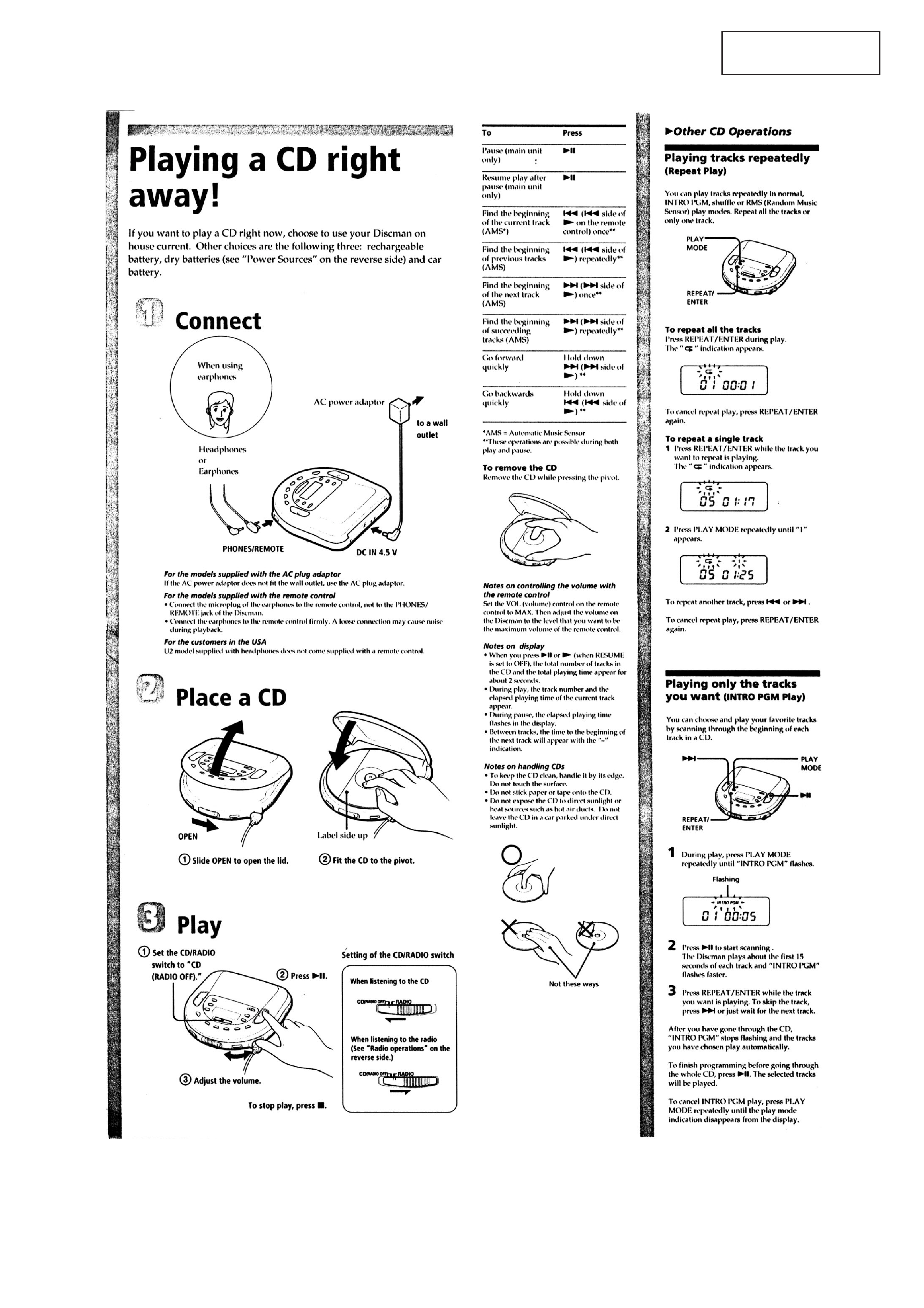
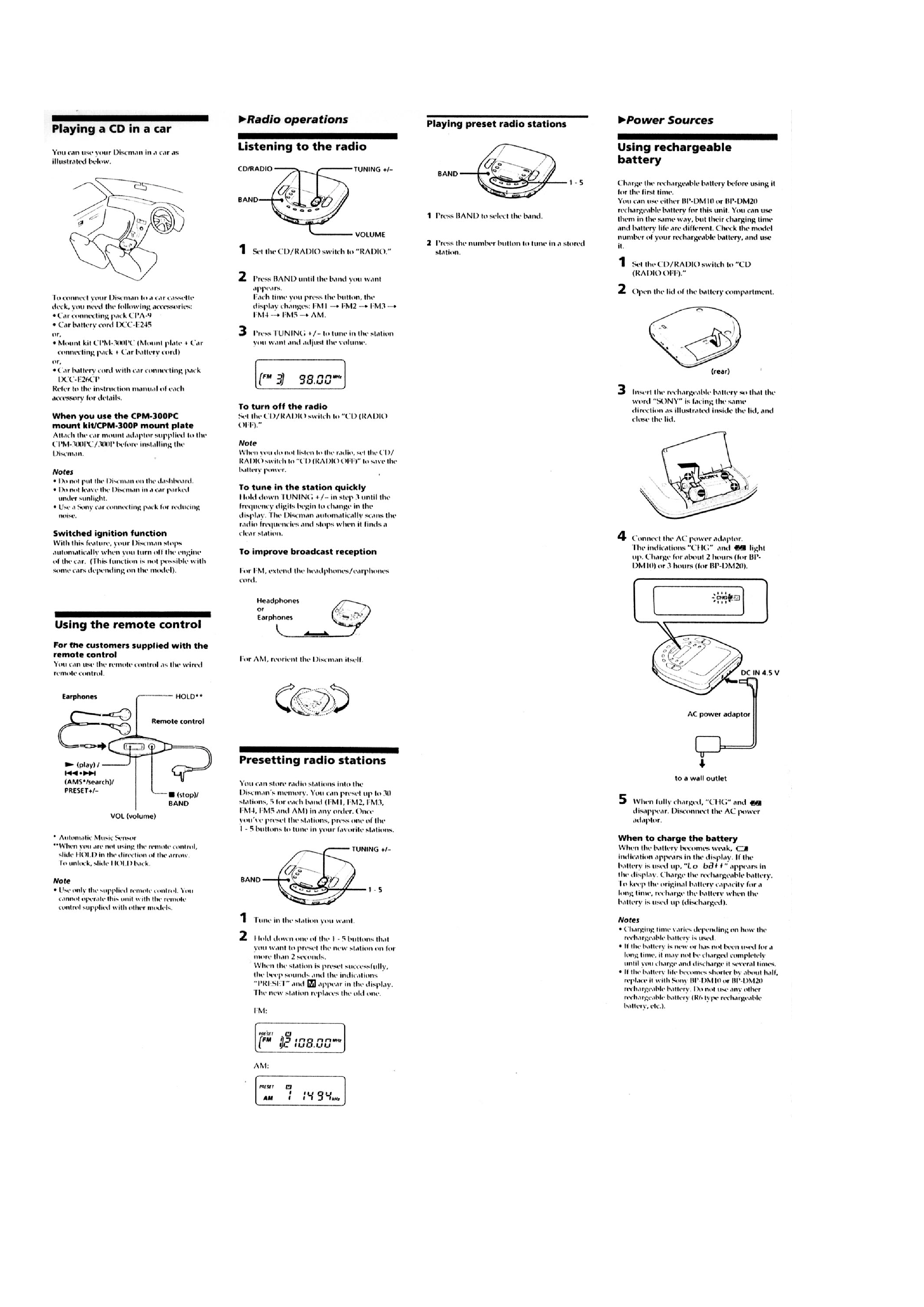
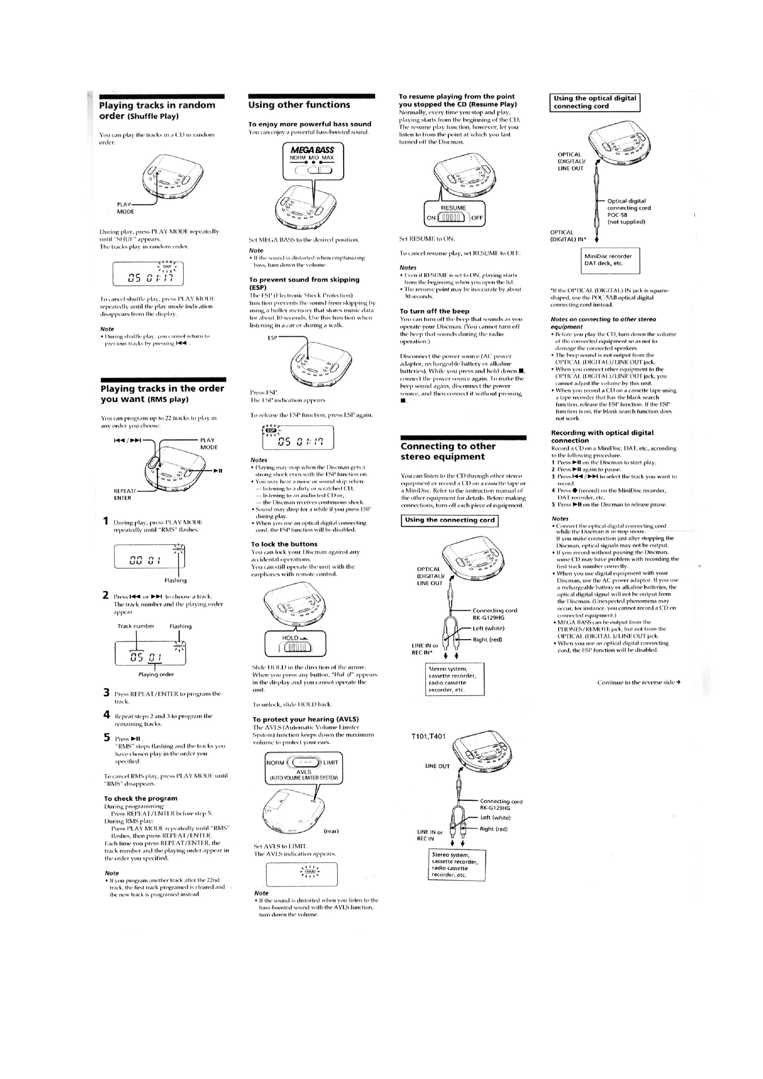
This section is extracted
from instruction manual.

-- 4 --

-- 5 --
