SERVICE MANUAL
MICROFILM
CHASSIS
SPECIFICATIONS
CPD-120AS
AEP Model
Chassis No. SCC-L13B-A-A
V-2
TRINITRON® MULTIMEDIA COMPUTER DISPLAY
Picture tube
CPD-120AS: 0.25 mm aperture grille
pitch, 15 inches measured diagonally
(13.9" viewable), 90-degree
deflection, AR coating
Viewable image size
CPD-120AS: Approx. 284
× 212 mm
(w/h) (11 1/4
× 8 3/8 inches) 13.9"
viewing image
Max resolution
Horizontal: Max. 1280 dots
Vertical: Max. 1024 lines
VESA standards
640
× 480 at 85 Hz
800
× 600 at 85 Hz
1024
× 768 at 85 Hz
1280
× 1024 at 60 Hz
Deflection frequency
Horizontal: 30 to 70 kHz
Vertical: 50 to 120 Hz
Speaker
Left, right: 3.5 W
× 2, Sub-woofer:
10 W 50 to 20 kHz
Microphones
Uni-direction, electret condenser
microphone
Microphones output
Miniplug
Audio input
Stereo miniplug, input impedance
47 k
, input level 0.7 Vrms typical
Headphones output
Stereo minijack, 4 mW + 4 mW at
16
Microphones input
Minijack, plug-in-power
USB pass-through
Upsteam
× 1, downstream × 1
Controls
Contrast/Audio level/Picture
enhancement/Brightness/Bass
Boost/(Audio level)/H.Size/V.Size/
Pincusion/Color tempeature/Audio
muting
AC input voltage/current
100 to 240 V, 50 60 Hz, 1.5 0.5 A
Dimensions
CPD-120AS: Approx. 424
× 425 ×
388 mm
(w/h/d) (16 3/4
× 16 3/4 × 15 3/8 inches)
(w/h/d) (19
× 19 1/8 × 16 7/8 inches)
Mass
CPD-120AS: Approx. 16.8 kg
(37 lb 1 oz)
Design and specifications are subject to change without notice.

2
CPD-120AS
DIAGNOSIS
Failure
Power LED
Mute LED
Scan/S cap Failure
Blink Amber
(On 1.5 sec, Off 0.5 sec)
ABL Failure
Blink Amber
(On 0.5 sec, Off 1.5 sec)
Audio Failure
Blink Amber
Blink Amber
(1 sec/cycle)
(1 sec/cycle)
Aging Mode : Raster aging
During Power Save, press "POWER switch" button for longer than 4 seconds.
Self Test : OSD color-bar indication
During Power Save, press "POWER switch" button for longer than 8 seconds.
Power
consumption
CPD-120AS
130 W (max)
CPD-220AS
150 W (max)
15 W (max)
10 W (max)
Approx. 10 W1)
Required
resumption time
--
--
Approx. 3 sec.
Approx. 10 sec.
--
u
Power
indicator
Green
Green
Green ~
Orange
Orange
Off
Normal
operation
Suspend (1st step
of power saving)
Active-off (2nd
step of power
saving)
Power-off
Power Saving Function
This display meets the power saving guidelines set by the International
ENERGYSTAR Program. It is capable of reduced power consumption when
usedwithacomputerequippedwithDisplayPowerManagementSignaling
(DPMS). By sensing the absence of the sync signal coming from the computer,
it will reduce the power consumption as follows:
CAUTION
ThePowerSavingfunctionwillautomaticallyputthedisplayintoActive-offstateifthe
powerswitchisturnedonwithoutanyvideosignalinput.Oncethehorizontaland
verticalsyncsaresensed,thedisplaywillautomaticallyreturntoitsNormaloperation
state.
Note
1) Tolowerthepowerconsumptionto0W,disconnectthepowercord.
Speaker
On
On
Off
Off
Off
State
1
2
3
4

CPD-120AS
3
PRIMARY MODE
PRIMARY
MODE AT PRODUCTION
MODE 1
MODE 2
MODE 3
MODE 4
MODE 5
MODE 6
MODE 7
MODE 8
MODE 9
MODE 10
RESOLUTION
640 X 480
800 X 600
800 X 600
1024 X 768
1024 X 768
1280 X 1024
640 X 400
640 X 480
1152 X 864
1152 X 432
CLOCK
36.000 MHz
40.000 MHz
49.500 MHz
78.750 MHz
94.500 MHz
108.500 MHz
25.175 MHz
25.175 MHz
80.000 MHz
65.000 MHz
-- HORIZONTAL --
H-FREQ
43.269 kHz
37.879 kHz
46.875 kHz
60.023 kHz
68.677 kHz
63.974 kHz
31.469 kHz
31.469 kHz
54.945 kHz
44.890 kHz
usec
usec
usec
usec
usec
usec
usec
usec
usec
usec
H. TOTAL
23.111
26.400
21.333
16.660
14.561
15.631
31.778
31.778
18.200
22.277
H. BLK
5.333
6.400
5.172
3.657
3.725
3.834
6.356
6.356
3.800
4.554
H. FP
1.556
1.000
0.323
0.203
0.508
0.590
0.636
0.636
0.800
1.354
H. SYNC
1.556
3.200
1.616
1.219
1.016
1.180
3.813
3.813
1.400
1.969
H. BP
2.222
2.200
3.232
2.235
2.201
2.065
1.907
1.907
1.600
1.231
H. ACTIV
17.778
20.000
16.162
13.003
10.836
11.797
25.422
25.422
14.400
17.723
-- VERTICAL --
V. FREQ(Hz)
85.008 Hz
60.317 Hz
75.000 Hz
75.029 Hz
84.997 Hz
60.013 Hz
70.086 Hz
59.940 Hz
59.984 Hz
94.804 Hz
lines
lines
lines
lines
lines
lines
lines
lines
lines
lines
V. TOTAL
509
628
625
800
808
1066
449
525
916
473.5
V. BLK
29
28
25
32
40
42
49
45
52
41.5
V. FP
1111
11
12
10
6
15
V. SYNC
3433
33225
4.5
V. BP
25
23
21
28
36
38
35
33
41
22
V. ACTIV
480
600
600
768
768
1024
400
480
864
432
-- SYNC --
INT(G)
NO
NO
NO
NO
NO
NO
NO
NO
NO
NO
EXT(H/V)/POLARITY
YES -/-
YES +/+
YES +/+
NO +/+
YES +/+
YES +/+
YES -/+
YES -/-
YES +/+
YES +/+
EXT(CS)/POLARITY
NO
NO
NO
NO
NO
NO
NO
NO
NO
NO
INT/NON INT
NON INT
NON INT
NON INT
NON INT
NON INT
NON INT
NON INT
NON INT
NON INT
INT
97.2.18 VER.
TIMING SPECIFICATION
WARNING!!
NEVER TURN ON THE POWER IN A CONDITION IN
WHICH THE DEGAUSS COIL HAS BEEN REMOVED.
SAFETY-RELATED COMPONENT WARNING!!
COMPONENTS IDENTIFIED BY SHADING AND MARK
¡
ON THE SCHEMATIC DIAGRAMS, EXPLODED VIEWS
AND IN THE PARTS LIST ARE CRITICAL FOR SAFE
OPERATION. REPLACE THESE COMPONENTS WITH
SONY PARTS WHOSE PART NUMBERS APPEAR AS
SHOWN IN THIS MANUAL OR IN SUPPLEMENTS
PUBLISHED BY SONY. CIRCUIT ADJUSTMENTS THAT
ARE CRITICAL FOR SAFE OPERATION ARE IDENTIFIED
IN THIS MANUAL. FOLLOW THESE PROCEDURES
WHENEVER CRITICAL COMPONENTS ARE REPLACED
OR IMPROPER OPERATION IS SUSPECTED.

CPD-120AS
4
TABLE OF CONTENTS
Section
Title
Page
1. GENERAL ...................................................................
5
2. DISASSEMBLY
2-1.
Cabinet Removal .................................................. 11
2-2.
Service Position
(1) D Board .......................................................... 11
(2) U Board .......................................................... 11
2-3.
D Board Removal ................................................. 12
2-4.
U Board Removal ................................................ 12
2-5.
Picture Tube Removal .......................................... 13
3. SAFETY RELATED ADJUSTMENT ............ 14
4. ADJUSTMENTS ...................................................... 15
5. DIAGRAMS
5-1.
Block Diagram
(with Frame Schematic Diagram) .................... 17
5-2.
Circuit Boards Location ....................................... 20
5-3.
Schematic Diagrams and Printed Wiring Boards ..... 20
(1) Schematic Diagram of D Board ........................... 21
(2) Schematic Diagrams of A and AE2 Boards ......... 29
(3) Schematic Diagrams of DA, J and U Boards ........ 33
5-4.
Semiconductors .................................................... 37
6. EXPLODED VIEWS
6-1.
Chassis ................................................................. 39
6-2.
Stand Block ........................................................... 40
6-3.
Packing Materials ................................................ 41
7. ELECTRICAL PARTS LIST ............................ 42

5
SECTION 1
GENERAL
The operating instructions mentioned here are partial abstracts
from the Operating Instruction Manual. The page numbers of
the Operating Instruction Manual remein as in the manual.
7GB
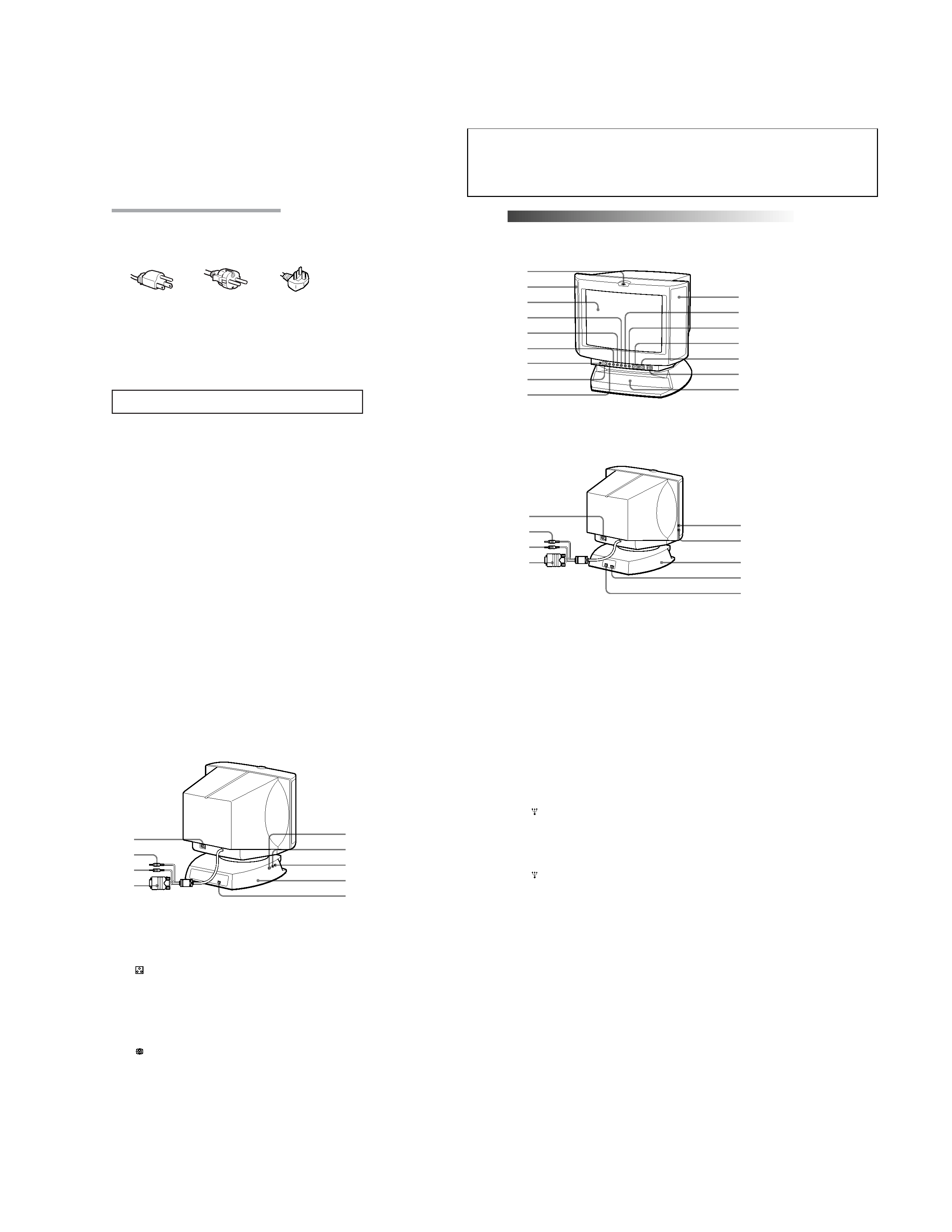
Functions of Controls
Functions of Controls
Front
1
2
3
4
5
6
7
8
9
2
!º
!¡
!TM
!£
!¢
!
Rear
p CPD-120AS
Continued to the next page
!§
@¡
@TM
!¶
@£
!·
@º
!ª
@¢
8GB
Functions of Controls
p CPD-220AS
!§
@¡
@º
!¶
@TM
!·
@£
!ª
@¢
1
2
3
4
5
6
7
8
9
!º
!¡
!TM
!£
!¢
!
Microphone
Main speaker
Display
Å Size button
d Geometry button
Color
temperature button
? Reset switch
¤ Mute button and
indicator
Volume/Bass
boost button
S Centering
button
Brightness/GPE
button
. Volume /+
buttons
> /+ Contrast
button
u Power switch
and indicator
Sub woofer
The internal microphone is turned off when an
external microphone is connected.
--
Displays OSD when adjusting.
Adjusts picture size (page 20).
Adjusts pincushion and rotation (pages 21, 22).
Adjusts color temperature (page 23).
Resets adjustments to factory setting (page 24).
Mutes sound (page 17).
Adjusts speaker volume or selects bass boost mode
(page 26).
Adjusts picture centering (page 19).
Adjusts picture brightness or selects GPE mode (page
25).
Adjusts speaker volume (page 16).
The default setting of the volume level is 30 %.
Adjusts picture contrast (page 17).
Turns on and off the display.
--
6GB
Warning on Power Connection
· Use the supplied power cord.
For the customers in UK.
If you use the display in UK, please use the supplied UK cable with UK plug.
for 100 to 120 V AC
for 220 to 240 V AC
for 240 V AC only
· Before disconnecting the power cord, wait at least 30 seconds after turning
off the power switch to discharge static electricity from the CRT display
surface.
· After the power has been turned on, the CRT is demagnetized for
approximately 5 seconds. This generates a strong magnetic field around the
bezel which may affect the data stored on magnetic tape or disks near the
bezel. Place such magnetic recording equipment and tapes/disks at a distance
from this unit.
The socket-outlet shall be installed near the equipment and shall be easily
accessible.
Precautions
9GB
!§
!¶
!·
!ª
@º
@¡
@TM
@£
@¢
AC IN connector
2 Audio plug (green)
h MIC plug (red)
; Video signal cable
(blue)
USB downstream
connector
h Microphone jack
2 Headphones jack
Tilt-Swivel
USB upstream
connector
Connect the supplied power cord (page 12).
Connect to the computer's speaker output
(page 11).
Connect to the computer's microphone input (page
11).
Connect to the computer's video output
(page 11).
Connect to a USB device (page 11).
Connect a microphone (not supplied).
Connect headphones (not supplied). The speakers are
turned off when headphones are connected.
Adjusts the angle of the display (page 14).
Connect to the computer's USB ports when using a
USB (universal serial bus) device connected to the
display (page 11).
Functions of Controls
