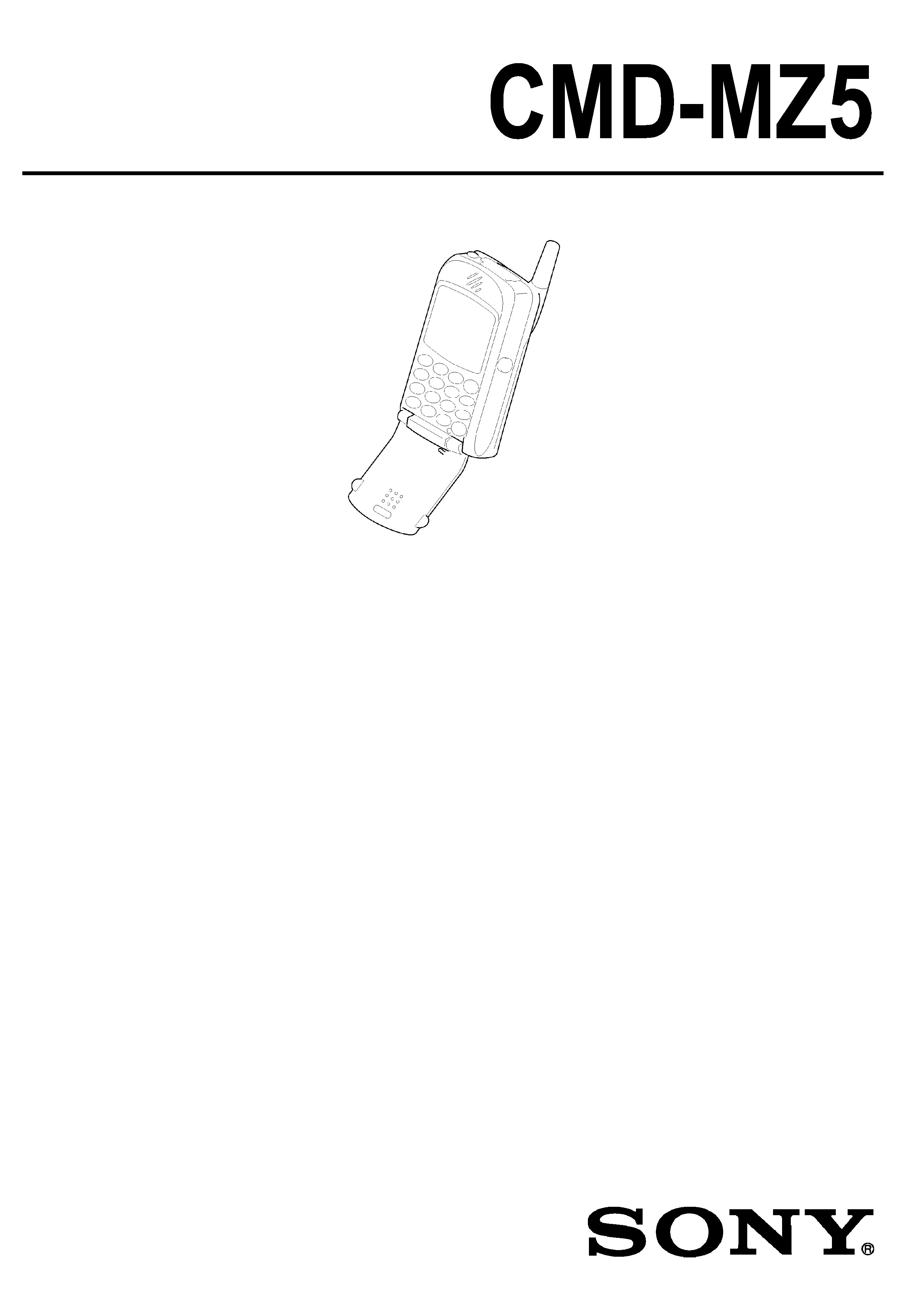
6(59,&(0$18$/
$(30RGHO
8.0RGHO
______________________________________________________________________________________________________________
SPECIFICATIONS
Signalling format
Dual-Band
Frequency range
E-GSM 900 MHz, Transmit:
880 ~ 915 MHz
Receive:
925 ~ 960 MHz
DCS 1800 MHz,
Transmit:
1710 ~ 1785 MHz
Receive:
1805 ~ 1880 MHz
GSM power class
Class 4 (2W)
DCS power class
Class 1 (1W)
SIM chip
Pluggable mini SIM card
Display
High resolution full graphics display
Resolution: 96 x 72 pixels
Graphic Icons
5 lines x 12 (normal font numeric) charactors
Channel spacing
200 kHz
Number of channels
E-GSM: 174
DCS : 374
Frequency stability
Transmit frequency drift (synchronized)
< ±
0,1 p.p.m
RF output power
GSM: 2W
DCS : 1W
Battery life
Standby : 30h - 130h
Talk time : 1h30 - 3h40
3257$%/(',*,7$/ &(//8/$57(/(3+21(
:,7+$&&(6625,(6

2
Power requirements
4.0 V (nominal)
Operating temperature
-10°C to +55°C
Accessories operating temperature
±
0°C to +45°C
Battery pack charging temperature
±
0°C to +40°C
Dimensions
90 x 50 x 30 mm
Weight
110 g (with Battery)
Supplied accessories
AC Adapter
QN-2TC
AC Cable
Europe
UK
Battery Pack
A-3627-234-A
Desktop Charger
1-476-508-11
Headphones
1-542-459-11
Remote with Microphone 1-476-509-11
Memory Stick
A-7094-682-A
Carry Bag
3-230-059-01
Optical Audio Cable
1-757-888-11
Analog Audio Cable
1-823-050-11
Optional accessories
Cigar Lighter Charger
QN-2CC
Handsfree kit
QN-MZ5HFK
EasyCom (SoftModem)
QN-2EC
PC-Card
QN-2PCM
Travel Charger
QN-2TC
Design and specifications are subject to change without notice.
This equipment complies with the essential requirements of the Directive 1999/5/EC Radio and
Telecommunications Terminal Equipment Directive.
NOTE
This device contains electrostatically sensitive components. Damage can occur to these components
if the appropriate handling is not adhered to.
ESD Handling precautions:
A working area in which Digital Cellular Telephones may be safely handled without undue risk of
damage from electrostatic discharge must be available.
The area must be equipped as follows:
½ All working surfaces must have a dissipative bench mat, safe for use with live equipment,
connected via 1.2M
resistor to a common ground point.
½ A quick release skin contact device with a flexible cord, which has a built-in safety resistor of
a range between 5.2K
and 1.2M shall be used. The flexible cord must be attached to a
dissipative earth point.
½ All containers and storage must be of the conductive type.

3
Batteries:
This device contains an internal battery in addition to the external battery pack. These batteries
are recyclable and should be disposed of in accordance with national legislation. They must not
be incinerated, or disposed of as ordinary rubbish.
CAUTION
Danger of explosion if battery is incorrectly replaced.
Replace only with the same or equivalent type
recommended by the manufacturer.
Discard
used
batteries
according
to
the
manufacturer's instructions.
ADVARSEL
Eksplosjonsfare ved feilaktig skifte av batteri.
Benytt samme batteritype eller en tilsvarende type
anbefalt av apparatfabrikanten.
Brukte batterier kasseres i henhold til fabrikantens
instruksjoner.
VARNING
Explosionsfara vid felaktigt batteribyte.
Använd samma batterityp eller en likvärdig typ som
rekommenderas av apparattillverkaren.
Kassera använt batteri enligt gällande föreskrifter.
VAROITUS
Paristo
voi
räjähtää,
jos
se
on
virheellisesti
asennettu. Vaihda paristo ainoastaan laitevalmistajan
suosittelemaan
tyyppiin.
Hävitä
käytetty
paristo
valmistajan ohjeiden mukaisesti.
ADVARSEL!
Lithiumbatteri-Eksplosionsfare ved fejlagtig håndtering.
Udskiftning må kun ske med batteri af samme fabrikat
og type.
Levér det brugte batteri tilbage til leverandøren.

4
TABLE OF CONTENTS
SECTION 1
Specifications ................................................................(see Cover sheet)
SECTION 2
General Descriptions
2.1 Multi Band ......................................................................... 06
2.2 Real Time Clock (RTC).......................................................... 06
2.3 Vibra Alert Functionality ........................................................ 06
2.4 Battery Safety ..................................................................... 06
2.5 Battery Charging ..................................................................07
2.6 Accessory Interface ............................................................. 07
2.7 RF Antenna connector / antenna switch ................................... 08
2.8 Languages ......................................................................... 08
2.9 Memory stick ...................................................................... 08
SECTION 3
Available Accessories
3.1 Hands free kit
QN-MZ5 HFK.................................. 09
3.2 Ciger Lighter Charger
QN-2 CC ........................................ 09
3.3 AC Adapter
QN-2 TC ........................................ 09
3.4 EasyCom (SoftModem)
QN-2 EC ........................................ 09
3.5 PCMCIA Card
QN-2 PCM ...................................... 09
3.6 Desktop Charger (not for sale by itself) .................................... 10
3.7 Standard Battery
QN-MZ5 (not for sale by itself) ............ 10
3.8 Magic Gate Memory Stick ...................................................... 10
3.9 Headphones (not for sale by itself) .......................................... 10
3.10 Remote with Microphone (not for sale by itself) ........................ 10
3.11 Optical Cable (not for sale by itself) ....................................... 10
3.12 Carry Bag (not for sale by itself) ............................................ 10
3.13 Analog Audio Cable (not for sale by itself) ............................... 10
SECTION 4
Operating Instructions
4.1 Parts and Controls ............................................................... 11
4.2 Basic Features .....................................................................12-13
4.3 Icon Glossary.......................................................................14
4.4 Menu Overview.................................................................... 15-16
SECTION 5
Disassembling / Testing
5.1 Disassembly ....................................................................... 17-19
5.2 Interface to GSM-Tester ........................................................ 20-21
5.3 Jigs & Tools ........................................................................ 21
SECTION 6
Programming Instructions
6.1 Requirement ...................................................................... 22
6.2 Hardware set-up ................................................................. 22
6.3 Software set-up .................................................................. 22
6.3.1 Download Software to Mobile ............................................ 23
6.3.2 Save Personal Data In Mobile............................................ 23

5
SECTION 7
Diagrams
7.1 RF Block
7.1.1 Block Diagram ................................................................ 24
7.1.2 Operational Description..................................................... 25-26
7.2 Base Band Block
7.2.1 Block Diagram (1/2) ......................................................... 27
7.2.2 Block Diagram (2/2).......................................................... 28
7.2.3 Operational Description..................................................... 29
7.3 Memory Stick Block .............................................................. 30
7.3.1 Block Diagram (1/2) ......................................................... 30
7.3.2 Block Diagram (2/2).......................................................... 31
7.3.3 Operational Description..................................................... 32
SECTION 8
Spare Parts and Accessories List
8.1 Spare Parts ....................................................................... 33
8.2 Accessories List ................................................................. 34
