PLASMA MONITOR
SERVICE MANUAL
FILE NO.
Model No. PDP-42WV1
PDP-42WV1S
(EUROPE, ASIA)
PDP42WV1A
PDP-42WV1AS
(U.S.A.)
ORIGINAL VERSION
PRODUCT CODE
1 110 017 00 PDP-42WV1, J3TF
1 110 023 00 PDP-42WV1A, J3TFA
1 110 043 00 PDP-42WV1S, J3TG
1 110 044 00 PDP-42WV1AS, J3TGA
REFERENCE NO.
SM5110505-00
Chassis No. PDP-42WV1-00
(PDP-42WV1)
NOTE: Match the Chassis No. on the
unit's back cover with the Chassis
No. in the Service Manual.
If the Original Version Service
Manual Chassis No. does not
match the unit's, additional
Service Literature is required. You
must refer to "Notices" to the
Original Service Manual prior to
servicing the unit.
CONTENTS
Pages
SAFETY INSTRUCTIONS --------------------------------------------------------------------- 2
TECHNICAL SPECIFICATIONS ------------------------------------------------------------- 3
DIMENSIONS AND OPTIONS---------------------------------------------------------------- 3
BATTERY REPLACEMENT ------------------------------------------------------------------- 4
MECHANICAL DISASSEMBLIES ------------------------------------------------------- 5 - 8
ADJUSTMENT ------------------------------------------------------------------------------ 9 - 16
CIRCUIT BLOCK DIAGRAM----------------------------------------------------------------- 17
POWER SUPPLY LINES --------------------------------------------------------------------- 18
POWER FAIL CIRCUIT ----------------------------------------------------------------- 19 - 21
TROUBLESHOOTING ------------------------------------------------------------------------ 22
CONTROL PORT FUNCTIONS ------------------------------------------------------ 23 - 24
PIN DESCRIPTION OF DIODE, TRANSISTOR AND IC ----------------------------- 25
PARTS LIST ------------------------------------------------------------------------------- 26 - 43
PARTS DESCRIPTION AND READING IN SCHEMATIC DIAGRAM ------------ 44
SCHEMATIC DIAGRAMS---------------------------------------------------------- A-1 - A-15
PRINTED WIRING BOARD DIAGRAMS ------------------------------------- A-16 - A-24
Chassis No. PDP-42WV1S-00
(PDP-42WV1S)
Chassis No. J3T-42WV1A00
(PDP-42WV1A)
Chassis No. J3T-42WV1AS00
(PDP-42WV1AS)
-2-
CAUTION :
TO REDUCE THE RISK OF ELECTRIC SHOCK, DO NOT REMOVE COVER (OR BACK). NO USER-
SERVICEABLE PARTS INSIDE. REFER SERVICING TO QUALIFIED SERVICE PERSONNEL.
THIS SYMBOL INDICATES THAT DANGEROUS
VOLTAGE CONSTITUTING A RISK OF ELECTRIC
SHOCK IS PRESENT WITHIN THIS UNIT.
THIS SYMBOL INDICATES THAT THERE ARE IMPORTANT
OPERATING AND MAINTENANCE INSTRUCTIONS IN THE
OWNER'S MANUAL WITH THIS UNIT.
CAUTION
RISK OF ELECTRIC SHOCK
DO NOT OPEN
SAFETY PRECAUTIONS
WARNING : TO REDUCE THE RISK OF FIRE OR ELECTRIC SHOCK, DO NOT EXPOSE THIS APPLIANCE TO
RAIN OR MOISTURE.
G This Plasma Monitor should be set in the way indicated. If not, it may result in a fire hazard.
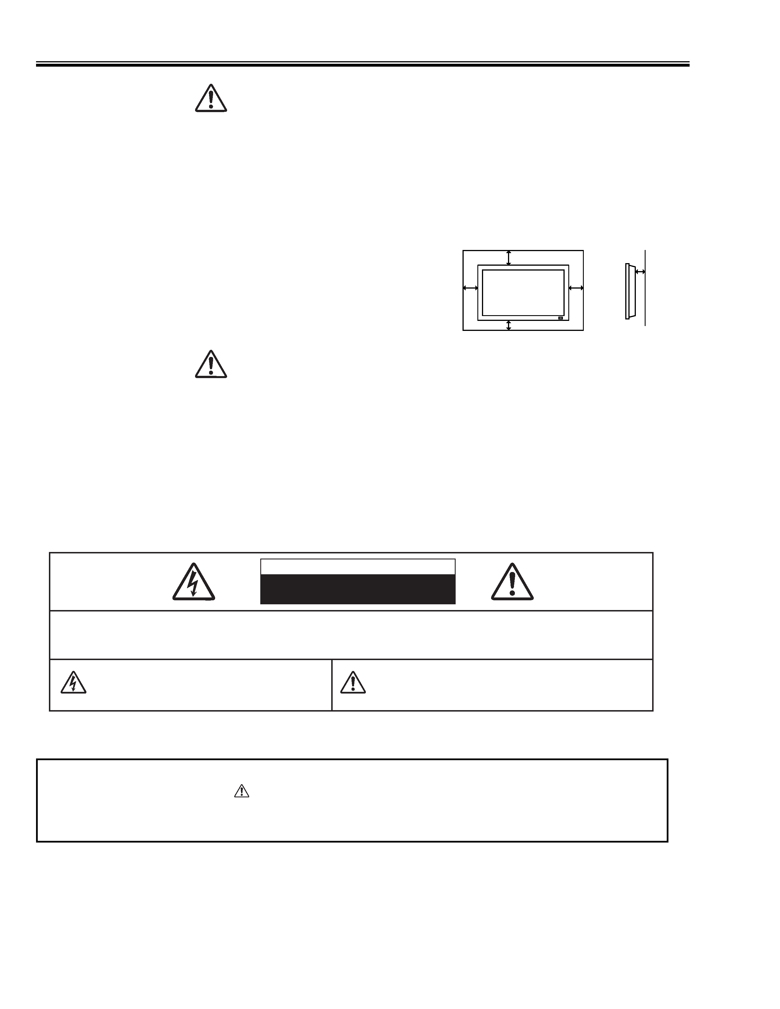
G Take appropriate space on the top, sides and rear of the Plasma Monitor cabinet for allowing air circulation and
cooling the Plasma Monitor. Minimum clearance must be maintained. If the Plasma Monitor is to be built into
a compartment or similarly enclosed, the minimum distances must
be maintained. Do not cover the ventilation slot on the Plasma
Monitor. Heat build-up can reduce the life of your Plasma
Monitor, and can also be dangerous.
G If the Plasma Monitor is not to be used for an extended time,
unplug the Plasma Monitor from the power outlet.
READ AND KEEP THIS OWNER'S MANUAL FOR LATER USE.
SIDE, TOP and BOTTOM
REAR
CAUTION IN INSTALLING
G Handle the Plasma Monitor carefully when installing it and do not drop.
G Locate set away from heat, excessive dust, and direct sunlight.
G For correct installation and mounting it is strongly recommended to use a trained, authorized dealer. Failure to
follow correct mounting procedures could result in damage to the equipment or injury to the installer.
10 cm
10 cm
10 cm
3 cm
NOTE :
When Plasma Monitor is not used for a long period of time, unlighting dots may be observed. This is caused by
characteristic of the Plasma Monitor. If this occurs, turn the Plasma Monitor on and leave it on about 1 hour. These
dots will gradually disappear.
6 cm
I Safety Instructions
Product safety should be considered when a component replacement is made in any area of the monitor.
Components indicated by mark
in the parts list and the schematic diagram designate components in
which safety can be of special significance. It is, therefore, particularly recommended that the replacement of
there parts must be made by exactly the same parts.
PRODUCT SAFETY NOTICE
-3-
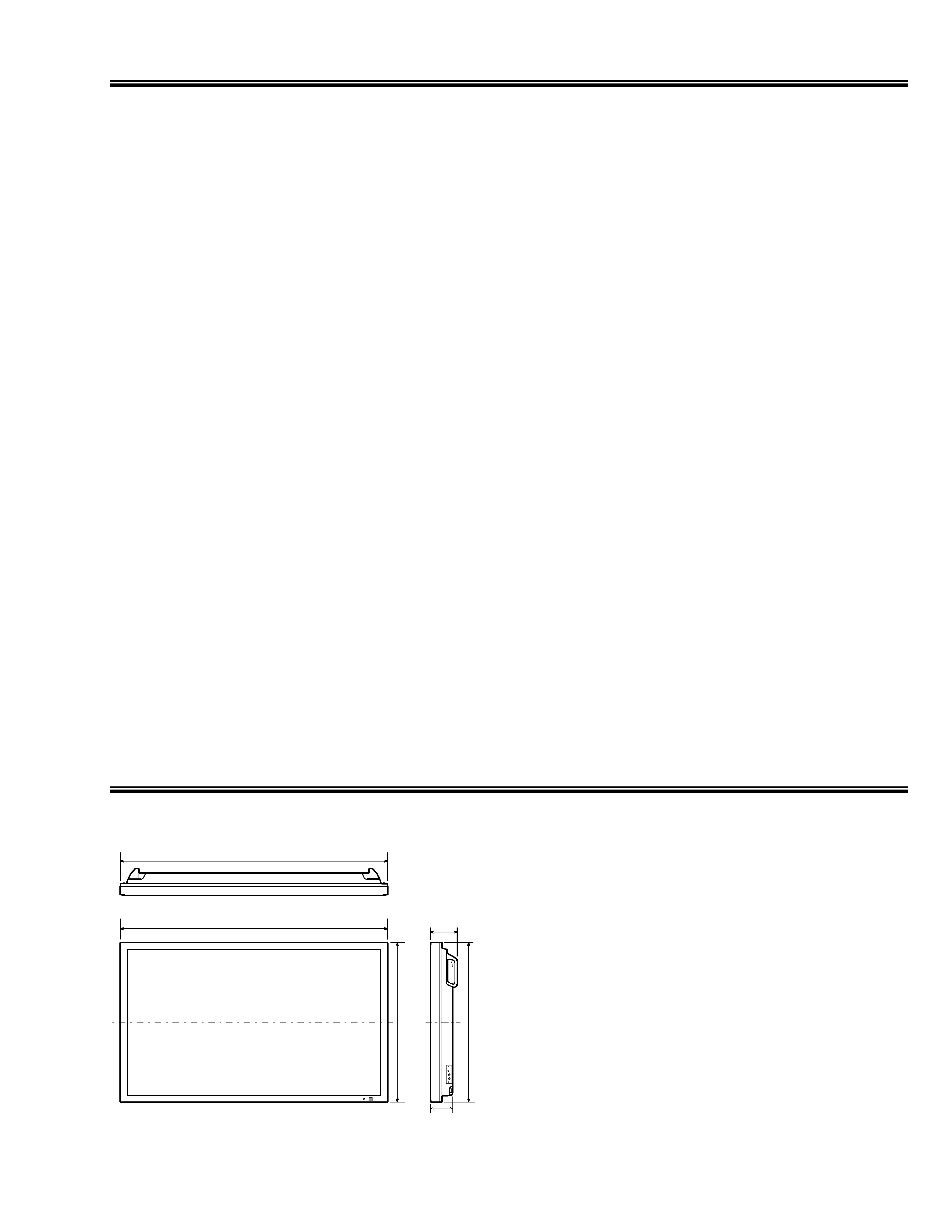
1022
(40.2)
1022
(40.2)
610
(24.0)
610
(24.0)
85
(3.4)
102
(4.0)
Dimensions and Options
MEASUREMENT
OPTIONS
Size in mm (inch)
The products listed below are optionally supplied.
When ordering these products, give name and Type No. to
sales dealer.
Speaker unit
KA-SX-42V (R and L)
(Color: Black)
KA-SX-42VS (R and L)
(Color: Silver)
Table top stand
KA-TD-42V
Tilt mount unit
KA-TI-42V
Wall mount unit
KA-WA-42V
Contact the sales dealer for other available options.
Technical Specifications
Screen Diagonal
42V
Product name
Multimedia Plasma Monitor
Panel type
Plasma Display Panel (16 x 9)
Display area
920 mm (W) x 518 mm (H)
Resolution / Color
852 x 480 pixels
PC Interface
RGB
Capability
Up to SXGA
Plug & Play
VESA DDC2B
Power Management
VESA DPMS
Audio Amp
10W + 10W (8 )
Terminals
PC IN
RGB (D-SUB 15pin)
AUDIO R / L (Stereo Mini jack)
WIRED RC IN / OUT
Mini Jack
EXT. SP OUT
R and L, 10W (8 ), Push type
POWER SUPPLY
AC 200 - 240V 50/60 Hz (PDP-42WV1/PDP-42WV1S)
AC 100 - 120V 50/60 Hz (PDP-42WV1A/PDP-42WV1AS)
DIMENSION (W x H x D)
1022 x 610 x 85 mm
( 402.4" x 240.2" x 33.5" ) (not including handles)
WEIGHT (NET)
29.8 kg
( 65.7 lbs ) (Plasma Monitor only)
Regulations
FCC CLASS-A, UL (PDP-42WV1A/PDP-42WV1S), CE (PDP-42WV1/PDP-42WV1S)
Environmental Considerations
Operating Temperature
0°C ~ 40°C
(32°F ~ 104°F )
Humidity
20 ~ 80%
Storage
Temperature
-10°C ~ 50°C
(14°F ~ 122°F)
Humidity
20 ~ 80 %
Accessories
Owner's Manual
AC Power Cord
Wired/Wireless Remote Control Transmitter and Batteries
Remote Control Cable
Ferrite Cores (x2)
-4-
I Battery Replacement
This Plasma Monitor is used a battery for Clock Function.
I Battery Replacement
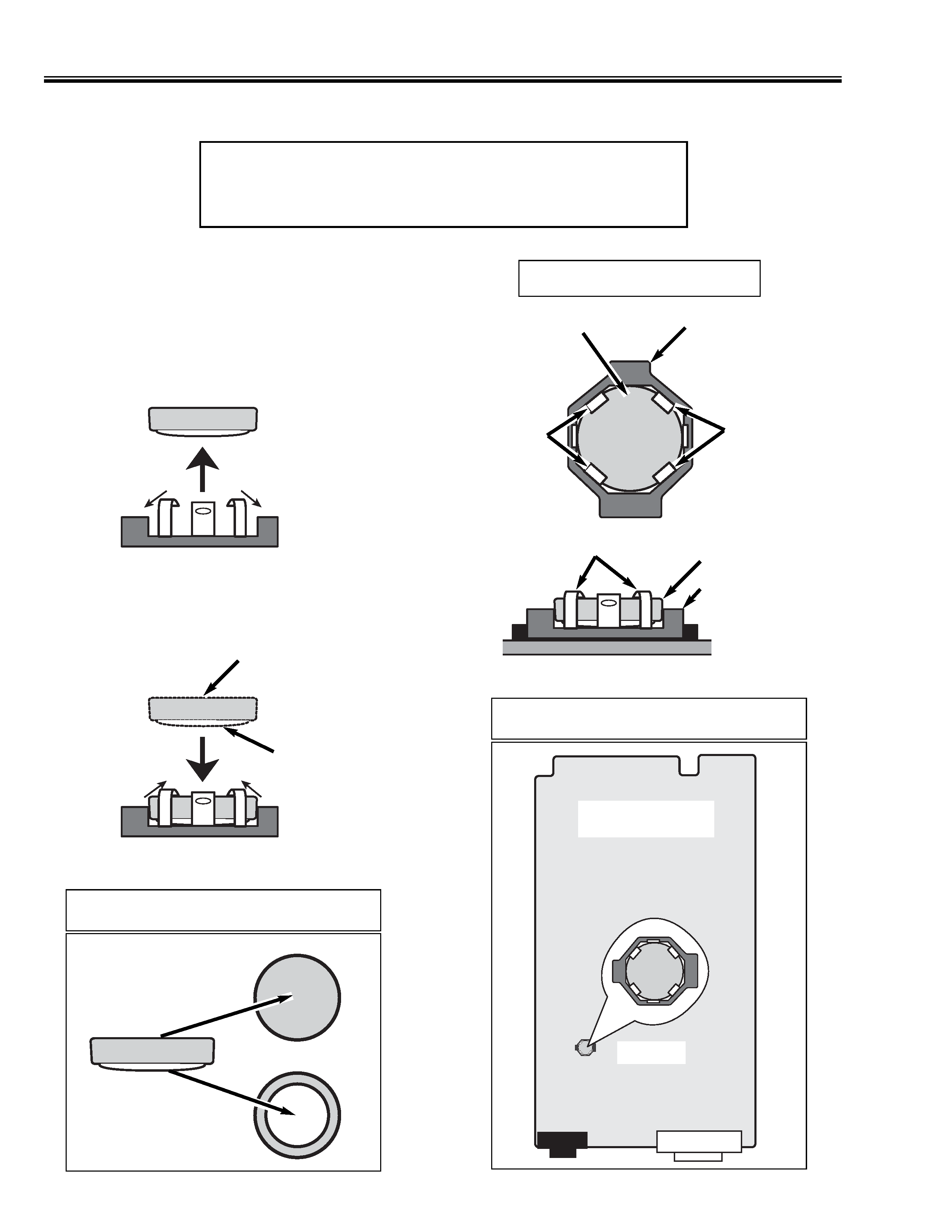
The battery is fixed to Main Board with Battery
Holder.
CAUTION
Danger of explosion if battery is incorrectly replaced.
Replace only with the same or equivalent type.
Battery Holder
Battery
Hook
Hook
Battery
Battery Holder
Hook
Main Board
Location of Battery
(+) Side
(-) Side
(1) Remove the battery from battery holder to bent
hooks slightly.
(2) Mount a new battery by correct polarity and
bent hooks back.
Polarity of Battery
(+) Side
(-) Side
Main Board
Battery
Parts No.: 645 059 8302
C
-5-
I Mechanical Disassemblies
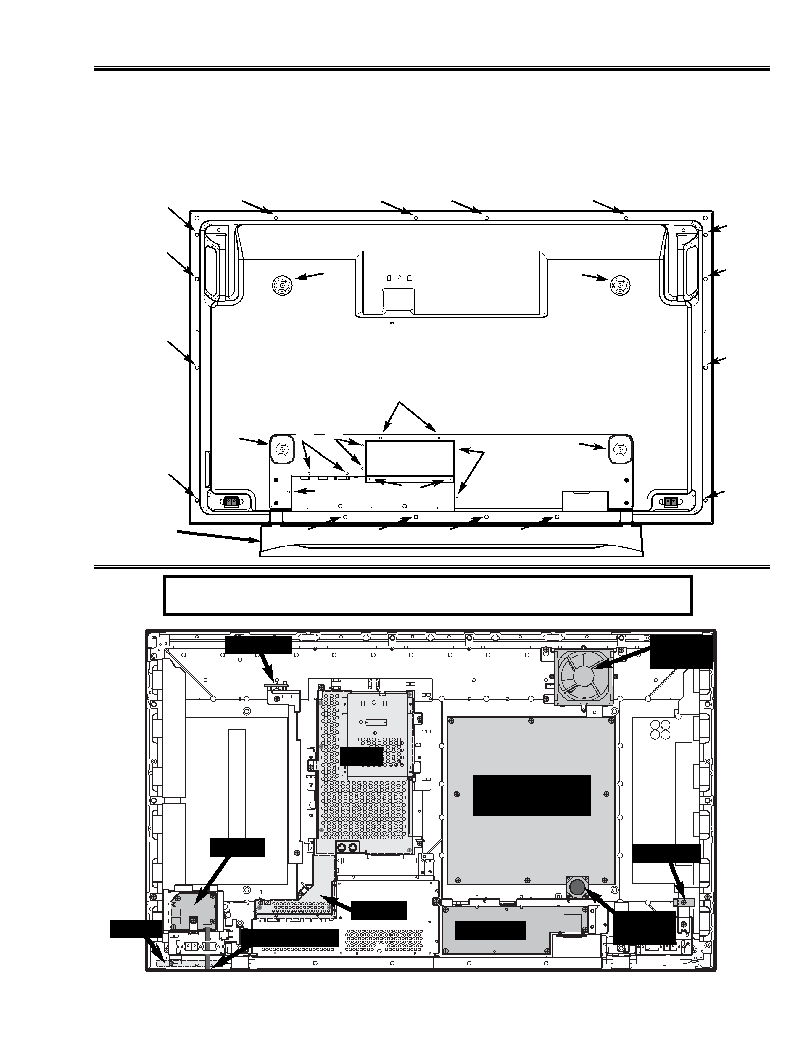
1. Cabinet Back Removal (Fig. 1)
Remove screws (A, B, C) and remove Cabinet Back as Fig. 1.
Note: For removal Option Slot Cocer, remove screws (D) and slide down.
A (4pcs: 8X20), B (9pcs: 3X6), C (16pcs: Special Screw), D (2pcs: 3X6)
Fig. 1
A
A
A
A
B
B
B
B
B
C
C
C
C
C
C
C
C
C
C
C
C
C
C
C
Option
Stand
D
Option
Slot Cover
Location of Circuit Board and Electric Parts
Main
Power
Main Power
Module
Jack-A
Jack-B
Sensor-A
Sensor-B
Fan
(FN1901)
Fan
(FN1903)
Control
Membrane SW
Note: Control Board and Membrane Switch are fixed at Cabinet Front.
Fig. 2
