FILE NO.
Service Manual
R
CONTENTS
DVD Home Theater System
AVD-8501
PRODUCT CODE No.
129 611 00 (US)
129 611 02 (CA)
129 611 03 (UK)
129 611 04 (XE)
129 611 06 (SS)
129 611 07 (AU)
REFERENCE No.
SM5810231
Specifications .............................................................................. 1
Laser beam safety precaution ..................................................... 2
DVD mechanism replacement .................................................... 2
Mechanism operation .................................................................. 4
DVD P.W.Board operation .......................................................... 5
Memo .......................................................................................... 7
DVD P.W.Board operation
(Schematic diagram for signal check) ......................................... 8
DVD P.W.Board operation
(Wiring diagram for signal check) ............................................... 18
DVD P.W.Board operation(Signal) .............................................. 20
DVD start-up program flow chart ................................................ 28
MPEG and FRONT END
P.W.Board operation (Block diagram) ...................................... 30
MPEG P.W.Board operation
(schematic diagram for waveform check) ................................... 32
MPEG and FRONT END
P.W.Board check waveform ...................................................... 34
How to load software for MPEG P.W.Board ............................... 38
Trouble shooting ......................................................................... 39
Voltage of IC & Transistor ........................................................... 42
Tuner Adjustment ........................................................................ 45
Exploded view (Cabinet & Chassis) ........................................... 46
Parts list ...................................................................................... 47
Exploded view & Parts list (DVD mechanism) ........................... 57
IC Block diagram & description ................................................... 58
Voltage of IC & Transistor ........................................................... 78
Wiring Diagram (MPEG A SIDE) ............................................... 80
Wiring Diagram (MPEG B SIDE) ............................................... 81
Schematic Diagram (MPEG) ...................................................... 84
Schematic Diagram (MAIN+STANDBY for US & CA) ................ 86
Wiring Diagram (MAIN for US & CA) ......................................... 88
Wiring Diagram (DVD POWER, HEADPHONE JACK
+ STANDBY for US & CA) .......................................................... 90
Wiring Diagram (DVD POWER, HEADPHONE JACK
+ STANDBY for UK & XE) .......................................................... 92
Schematic Diagram (MAIN+STANDBY for UK& XE) ................. 94
Wiring Diagram (MAIN for UK & XE) ......................................... 96
Schematic Diagram (MAIN+STANDBY for SS) ......................... 98
Wiring Diagram (MAIN for SS) ................................................... 100
Schematic Diagram (MAIN+STANDBY for AU) ......................... 102
Wiring Diagram (MAIN for AU) ................................................... 104
Wiring Diagram (DVD POWER, HEADPHONE JACK,
STANDBY+ AC VOLTAGE SWITCH for SS & AU) .................... 106
Schematic Diagram (FRONT + LED SW for US & CA) ............. 108
Schematic Diagram (TUNER for US & CA) ............................... 110
Wiring Diagram (FRONT, TUNER + LED SWITCH
FOR US & CA) ........................................................................... 112
Schematic Diagram (FRONT + LED SW for UK & XE) .............. 114
Wiring Diagram (FRONT, TUNER + LED SWITCH
FOR UK & XE) ........................................................................... 116
Schematic Diagram (TUNER for UK & XE) ............................... 118
Schematic Diagram (FRONT+ LED SW for SS & AU) ............... 120
Wiring Diagram (FRONT, TUNER + LED SWITCH
FOR SS & AU) ........................................................................... 122
Schematic Diagram (TUNER for SS & AU) ............................... 124
Schematic Diagram (VIDEO for US & CA) ................................ 126
Wiring Diagram (VIDEO for US & CA) ....................................... 128
Schematic Diagram (VIDEO for UK & XE) ................................. 130
Wiring Diagram (VIDEO for UK & XE) ....................................... 132
Schematic Diagram (VIDEO for SS & AU) ................................. 134
Wiring Diagram (VIDEO for SS & AU) ....................................... 136
Schematic Diagram (DVD) .......................................................... 138
Schematic Diagram (DVD TOP LEFT) ....................................... 140
Schematic Diagram (DVD BOTTOM LEFT) ............................... 142
Schematic Diagram (DVD TOP RIGHT) ..................................... 144
Schematic Diagram (DVD BOTTOM RIGHT) ............................. 146
Wiring Diagram (DVD A SIDE) ................................................... 148
Wiring Diagram (DVD B SIDE) ................................................... 149
FL & Descriptrion ........................................................................ 150
(CA)
(UK)
(XE)
(SS)
(AU)
(US)
DCS-AVD8501
This system consists as follows.
US: JCX-AVD8501(Main unit: 129 606 00), "SX-STM-8501S"(Speaker system: 165 032 00) & "SX-STM-8501W"(Speaker system: 165 033 00)
CA: JCX-AVD8501(Main unit: 129 606 02), "SX-8501S"(Speaker system: 165 032 01) & "SX-8501W"(Speaker system: 165 033 01)
UK: JCX-AVD8501(Main unit: 129 606 03), "SX-8501S"(Speaker system: 165 032 05) & "SX-8501W"(Speaker system: 165 033 02)
XE: JCX-AVD8501(Main unit: 129 606 04), "SX-8501S"(Speaker system: 165 032 06) & "SX-8501W"(Speaker system: 165 033 04)
SS: JCX-AVD8501(Main unit: 129 606 06), "SX-8501S"(Speaker system: 165 032 02) & "SX-8501W"(Speaker system: 165 033 02)
AU: JCX-AVD8501(Main unit: 129 606 07), "SX-8501S"(Speaker system: 165 032 05) & "SX-8501W"(Speaker system: 165 033 02)
PAUSE/ST
EP
PRE
V
NE
XT
-TU
NE
TUN
E+
STOP
REV
SLOW
FWD
SLOW
CLEAR
TRIM
REMOTE CONTROL REM-A8501/US
TEST TONE
FUNCTION
FM MODE
PRESET
SOUND
BASS
SURROUND
+
-
MUTE
TU/BAND
RETURN
ON SCREEN
PROG
TV CH+
TV VOL+
TV VOL-
TV CH-
TV/VIDEO
LAST MEMO
REPEAT
SEARCH MODE
TV POWER
/ ON
ENTER
SHIFT
S
E
T
UP
T
IT
LE
SU
BT
IT
LE
M
EN
U
PLAY
FW
D
RE
V
0
8
79
+10
5
46
2
13
ANGLE
A.REPLAY
ZOOM
AUDIO
SLEEP
TIMER
ADJUST
SET/CLEAR
CLOCK
VOLUME

- 1 -
SPECIFICATIONS
IMPORTANT INFORMATION
Because its products are subject to continuous improvement, SANYO reserves the right to modify product designs and specifications
without notice and without incurring any obligation.
Specifications subject to change without notice.
Amplifier Section
for US
Main Amplifier (Stereo mode)
Continuous minimum sine wave RMS power output per
channel into 8 ohms at 1kHz with no more than 10% total
harmonic distortion .......................................... 33.5 Watts
Main Amplifier (Dolby Digital mode)
Continuous minimum sine wave RMS power output per
channel into 8 ohms at 1kHz with no more than 10% total
harmonic distortion (with Center/Surround/Subwoofer
amplifier off) ...................................................... 33.5 Watts
Center Channel Amplifier (Center)
Continuous minimum sine wave RMS power output into 8 ohms
at 1kHz with no more than 10% total harmonic distortion (with
Main/Surround/Subwoofer amplifier off) ............ 33.5 Watts
Surround Channel Amplifier (Surround)
Continuous minimum sine wave RMS power output per
channel into 8 ohms at 1kHz with no more than 10% total
harmonic distortion (with Main/Center/Subwoofer ampli-
fier off) ................................................................ 33.5 Watts
Subwoofer Channel Amplifier (Subwoofer)
Continuous minimum sine wave RMS power output into 8 ohms
at 100Hz with no more than 10% total harmonic distortion (with
Main/Center/Surround amplifier off) ............... 33.5 Watts
for UK,XE,SS,AU
Main amplifier
Stereo mode
30 W x 2 (at 8 ohms, 10% distortion)
Dolby Digital mode
30 W x 2 (at 8 ohms, 10% distortion, with Centre/Surround/
Subwoofer amplifier off)
Center amplifier
30 W (at 8 ohms, 10% distortion, with Main/Surround/
Subwoofer amplifier off)
Surround amplifier
30 W x 2 (at 8 ohms, 10% distortion, with Main/Centre/
Subwoofer amplifier off)
Subwoofer amplifier
30 W (at 8 ohms, 10% distortion, with Main/Centre/Surround
amplifier off)
Input level, Output level and impedance:
VIDEO 1:
VIDEO IN: 1.0 Vp-p (75 )
AUDIO IN (L/R): 300 mV/50 k (US,CA)
AUDIO IN (L/R): 800 mV/50 K (SS,AU)
VIDEO OUT: 1.0 Vp-p (75 ) (Except UK,XE)
AUDIO OUT (L/R): 300 mV/2.2 k (Except UK,XE)
VIDEO 2:
VIDEO IN: 1.0 Vp-p (75 ) (Except UK,XE)
AUDIO IN (L/R): 300 mV/50 k (US,CA)
AUDIO IN (L/R): 800 mV/50 K (SS,AU)
For Euro-AV cable (UK,XE)
Outputs:
FRONT SPEAKERS (L/R): 8
CENTER SPEAKER: 8
SURROUND SPEAKERS (L/R): 8
SUBWOOFER: 8
DVD Video Player Section
Type: DVD Video player
Signal format:
NTSC color (US,CA) PAL or NTSC (Except US,CA)
Laser:
Semiconductor laser, wavelength 650 nm/790 nm
Laser output (Continuous wave max.)
1mW (DVD)
0.5mW (CD)
Frequency range (digital audio):
4 Hz to 44 kHz (DVD fs: 96 kHz)
Signal to noise ratio: More than 105 dB
Harmonic distortion (digital audio): 0.003 %
Wow and flutter: Below measurable level
Tuner Section
(FM)
Frequency range: 87.9 MHz ~ 107.9 MHz (200 kHz steps)(US,CA)
: 87.5 MHz~ 108MHz (Except US,CA)
(AM)
Frequency range: 520 kHz ~ 1,710 kHz (10 kHz steps) (US,CA)
: 522 kHz ~ 1,611 kHz (UK,XE,AU)
: 522 kHz ~ 1,710 kHz (9 kHz steps) (SS)
520 kHz ~ 1,710 kHz (10 kHz steps) (SS)
General
Power requirements: AC 120 V, 60 Hz (US,CA)
: AC 230 V, 50 Hz (UK,XE)
: AC 110 - 120/220 - 240 V, 50/60 Hz (SS)
: AC 230 - 240 V, 50 Hz (AU)
Power consumption: 230 Watts (US,CA)
: 170 Watts (Except US,CA)
Dimensions (W x H x D): Approx. 435 (W) x 90 (H) x 115 (D) mm
Weight: Approx. 7.9 kg (17.2 lbs)
Speaker System
Front left, Front right, Center, Surround left and Surround
right speakers
Unit used : 8 cm, Cone type, Full range
Maximum music power handling capacity : 60 Watts
Nominal impedance: 8
Dimensions (W x H x D) : Approx. 150 x 110 x 115 mm
Weight : Approx. 0.75 kg (1.6 lbs)/speaker
Subwoofer
Unit used : 13 cm, Cone type
Maximum music power handling capacity : 60 Watts
Nominal impedance : 8
Dimensions (W x H x D): Approx. 180 x 390 x 290 mm
Weight : Approx. 5.7 kg (12.6 lbs)
COMPONENT VIDEO OUT (Except UK,XE):
Y: 1.0 Vp-p (75 )
CB: 0.7 Vp-p (75 )
CR: 0.7 Vp-p (75 )
A/V EURO CONNECTOR (MONITOR OUT):
For Euro-AV cable (UK,XE)
MONITOR OUT S-VIDEO OUT:
Y: 1.0 Vp-p (75 )
C: 0.286 Vp-p (75 ) (US,CA)
C: 0.286 Vp-p (75 )NTSC, 0.3 Vp-p (75 )PAL
(Except US,CA)
MONITOR OUT VIDEO: 1.0 Vp-p (75 )

- 2 -
DVD MECHANISM REPLACEMENT
1. Cautionary instructions in handling the assy
(Safety instructions)
Optical pickup
The laser beam used in the pickup is classified as "class 2". Exposing
your eyes or skin to the beam is harmful. Take care not to do so.
(Caution against static electricity and leakage voltage)
Ground securely the work tables, tools, fixtures, soldering irons
(including those made of ceramic) and measuring instruments used
in the production lines and inspection departments that handle
loaders. The workers shall also be grounded.
(Cautionary instructions in handling)
Do not touch the object lens when handling a loader, or the lens
will be stained, resulting in inadequate playability.
There is no power supply protection circuit provided for this product
or adjustment/inspection device. Short-circuiting may lead to fire or
damage.
Take care so as to protect from exposure to water, the entry of
metallic pieces or dew condensation.
In particular, a strong magnet adjacent to the pickup will not only
get inoperative but can damage the pickup if a small metallic piece,
such as a screw or swarm, enters.
The loader edge can cause injury if inadvertently handled.
Do not touch a rotating disk, or injury may result.
This product is a precision device. Handle carefully.
A shock or dropping will cause misalignment or destruction. If it
should occur, refer to clause 2.
This product is so designed as to endure an initial shock equivalent
to a drop from a height of approx. 90 cm under the packed condition.
After the initial shock, the resistivity will still remain at a level of 50
to 60 G, but the mechanical robustness
The entry and deposition of dirt into or on the pickup lens or moving
section will cause malfunction or degradation.
(Connectors)
Do not connect or disconnect while power is on.
Connecting or disconnecting signal wires or the main power cord
when the power is on may destruct the unit or fixture.
When connecting, push all the way in securely.
An insufficient insertion may cause a bad contact, leading to an
erroneous operation.
Do not connect or disconnect roughly by an excessively strong force,
or a broken wire or bad contact may result.
Semiconductors are connected. Do not touch connector terminals
directly.
If the worker is grounded, there is nothing to worry about static
electricity, but the rust on the connector terminal surface caused
by the touch may result in bad contact.
(Power source)
The power source need be good in quality (free from instantaneous
interruptions or noises).
A low quality power source may well cause malfunction.
(Storage)
Do not place or store in a dusty place or a place where dew
condensation is possible.
The entry and deposition of dirt or dust into or on the pickup lens or
moving section will cause malfunction or degradation.
Also, dew condensation causes rust ; the rust penetrate into the
precision part of a pickup, causing malfunction, or degrading the
optical quality of the internal lens and reflector, which also leads to
malfunction.
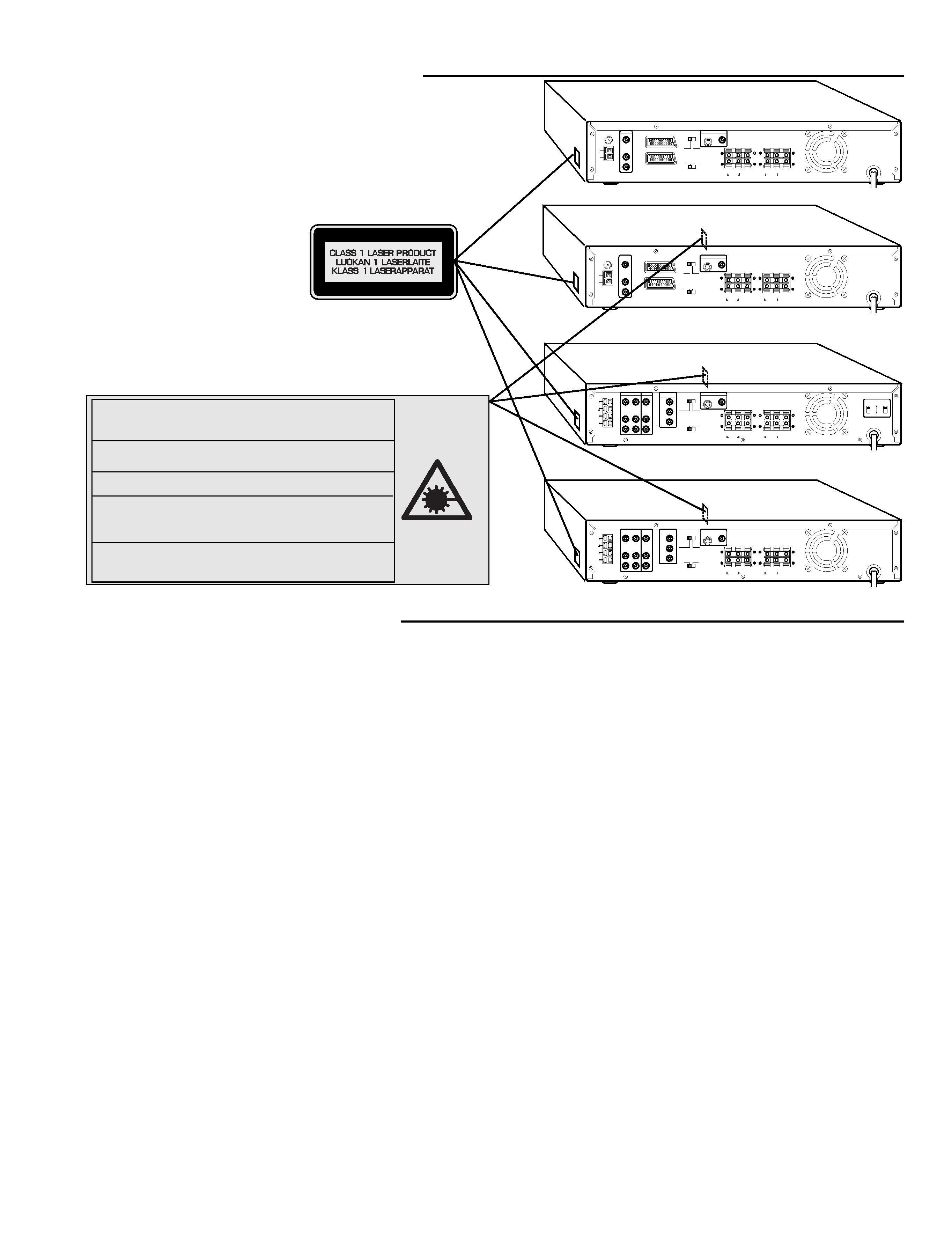
LASER BEAM SAFETY PRECAUTION
UK,XE,SS,AU
UK
VIDEO 1
ANT
FM
(75
)
AM
LOOP
R
L
VIDEO IN
AUDIO IN
VIDEO
S-VIDEO
(DVD ONLY)
MONITOR OUT
R
L
CENTER
FRONT
RL SUB WOOFER
SURROUND
SPEAKERS 8
VIDEO OUT SELECT
(DVD ONLY)
S-VIDEO
RGB
NTSC
PAL
TV SYSTEM
A/V EURO CONNECTOR
(MONITOR OUT)
VIDEO 2 (IN)
CR
CB
Y
COMPONENT
VIDEO OUT
R
L
VIDEO 2
VIDEO 1
ANT
FM
75
AM
LOOP
VIDEO IN
AUDIO IN
R
L
VIDEO IN
AUDIO IN
VIDEO OUT
AUDIO OUT
VIDEO
S-VIDEO
(DVD ONLY)
MONITOR OUT
R
L
CENTER
FRONT
RL SUB WOOFER
SURROUND
SPEAKERS 8
VIDEO OUT SELECT
(DVD ONLY)
S-VIDEO
COMPONENT
NTSC
PAL
TV SYSTEM
VOLTAGE SELECTOR
SUB
SUB
MAIN
MAIN
220-240V
110-120V
SS
VIDEO 1
ANT
FM
(75
)
AM
LOOP
R
L
VIDEO IN
AUDIO IN
VIDEO
S-VIDEO
(DVD ONLY)
MONITOR OUT
R
L
CENTER
FRONT
RL SUB WOOFER
SURROUND
SPEAKERS 8
VIDEO OUT SELECT
(DVD ONLY)
S-VIDEO
RGB
NTSC
PAL
TV SYSTEM
A/V EURO CONNECTOR
(MONITOR OUT)
VIDEO 2 (IN)
XE
CR
CB
Y
COMPONENT
VIDEO OUT
R
L
VIDEO 2
VIDEO 1
ANT
FM
75
AM
LOOP
VIDEO IN
AUDIO IN
R
L
VIDEO IN
AUDIO IN
VIDEO OUT
AUDIO OUT
VIDEO
S-VIDEO
(DVD ONLY)
MONITOR OUT
R
L
CENTER
FRONT
RL SUB WOOFER
SURROUND
SPEAKERS 8
VIDEO OUT SELECT
(DVD ONLY)
S-VIDEO
COMPONENT
NTSC
PAL
TV SYSTEM
CAUTION Ð INVISIBLE LASER RADIATION WHEN OPEN AND
INTERLOCKS DEFEATED. AVOID EXPOSURE TO BEAM.
ADVARSEL Ð USYNLIG LASER STR·LING VED ·BNING, N·R
SIKKERHEDSAFBRYDERE ER UDE AF FUNKTION, UNDG· UDS
®TTELSE FOR STR·LING.
VARNING Ð OSYNLIG LASER STR·LNING NR DENNA DEL R ...PPNAD
OCH SPRR R URKOPPLAD. STR·LEN R FARLIG.
VORSICHT Ð UNSICHTBARE LASERSTRAHLUNG TRITT AUS, WENN
DECKEL GE...FFNET UND WENN SICHERHEITSVERRIEGELUNG
BERBRCKT IST. NICHT, DEM STRAHL AUSSETZEN.
VARO Ð AVATTAESSA JA SUOJALUKITUS OHITETTAESSA OLET
ALTTIINANKYMTT...MLLE LASERSTEILYLLE. L KATSO
STEESEEN.
AU

- 3 -
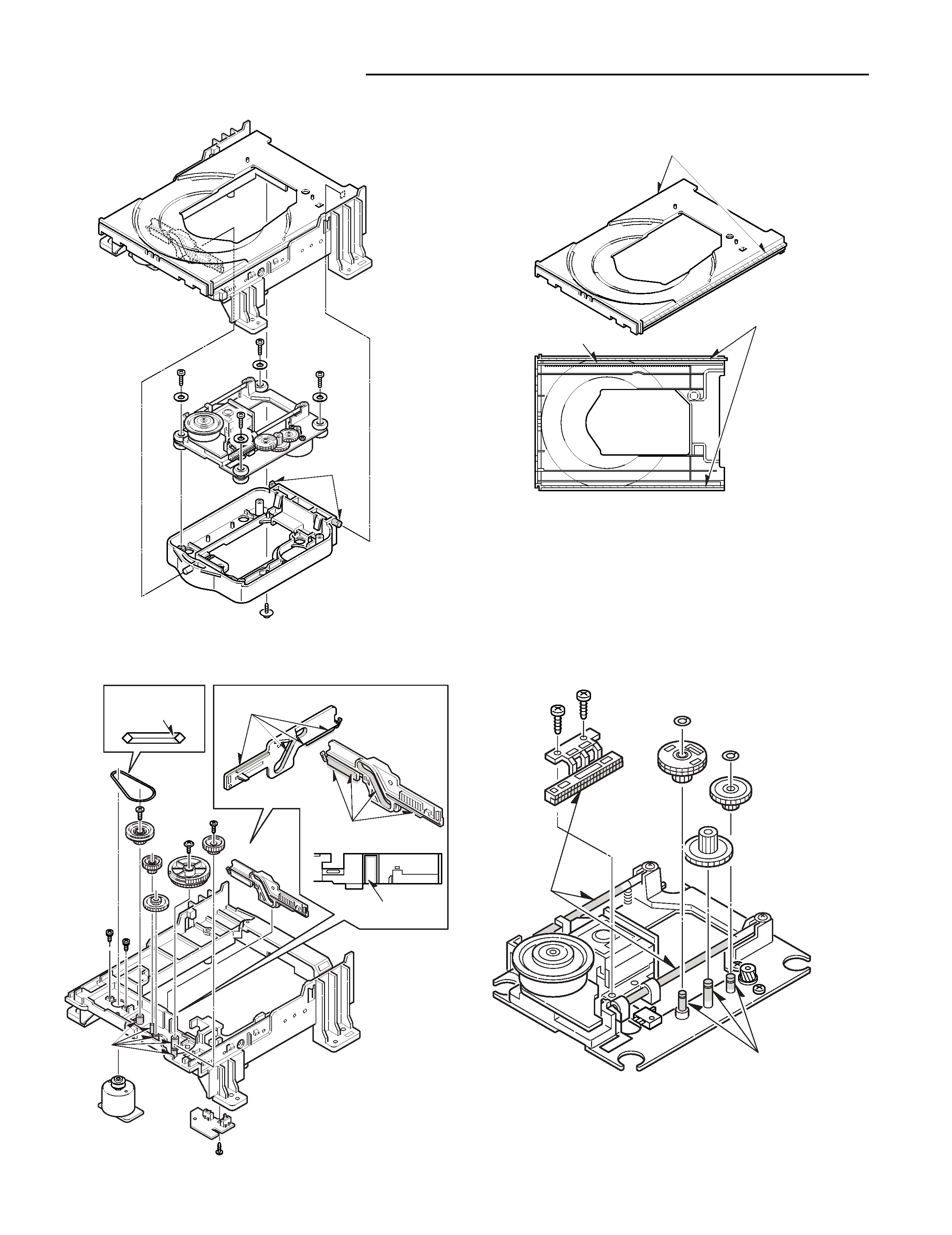
DVD MECHANISM REPLACEMENT
1. TRAY and BASE MechanismPart
2. BASE Mechanism Mounting Part
FLOIL OIL
G-474B
MOLYKOTE
EM-50L
MOLYKOTE
EM-50L
MOLYKOTE
EM-50L
MOLYKOTE
EM-50L
SILICON GREASE
KS-64
3. TRAY Part
MOLYKOTE
EM-50L
GREASE
CDF-409
GREASE
CDF-409
4. BASE Mechanism Part
FLOIL OIL
G-2000B
FLOIL OIL
G-2000B
Do not remove the pick-up from base mechanism because of
adjustment difficulty.

- 4 -
MECHANISM OPERATION
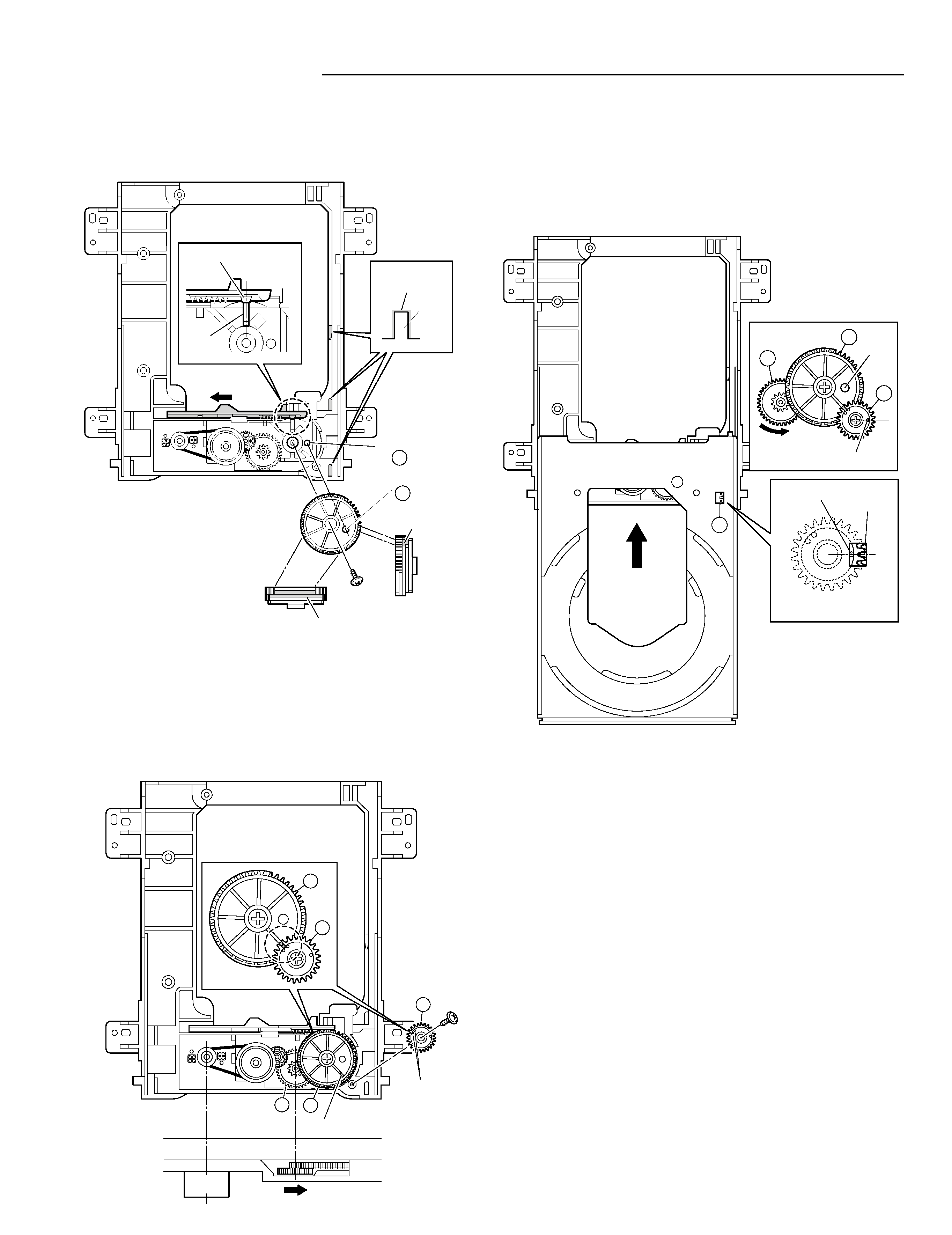
1.How to setting the TRAY
1. Move the SLIDE left side.
2. Match the Hole of GEAR 5 and Hole of CHASSIS 4.
CHASSIS
FRONT SIDE
MOTOR
MARKER
MARKER
1
2
2
3
3
3. Match the mark of GEAR 2 and mark of GEAR 3, and then
install the BOSS.
4. Turn the GEAR 1 counterclockwise, and then SLIDE move
right side.
5. The GEAR 1 move from side to side.
RIB
RIB
GREASE
EM-50L
GREASE
EM-50L
GREASE
EM-50L
LARGE TOOTH
GEAR HOLE
CHASSIS HOLE
5
4
6. Match the hole of GEAR 7 and hole of chassis while turning
GEAR 6.
7. Match the mark of LOADING GEAR 8 and gear of TRAY
where see horn hole 9 of tray.
8. Push a TRAY with the state that turned the entire surface of a
TRAY into approximately 5 degrees the lower part slowly.
LOARDING
GEAR
MARKER
MARKER
TRAY
HOLE
6
7
8
9
