ORDER NO.
PIONEER ELECTRONIC CORPORATION 4-1, Meguro 1-Chome, Meguro-ku, Tokyo 153-8654, Japan
PIONEER ELECTRONICS SERVICE, INC. P.O. Box 1760, Long Beach, CA 90801-1760, U.S.A.
PIONEER ELECTRONIC (EUROPE) N.V. Haven 1087, Keetberglaan 1, 9120 Melsele, Belgium
PIONEER ELECTRONICS ASIACENTRE PTE. LTD. 253 Alexandra Road, #04-01, Singapore 159936
PIONEER ELECTRONIC CORPORATION 1999
c
TS-WX20LPA
TRT1123
H IZX JUNE 1999 Printed in Japan
LINEAR POWER ACTIVE SUBWOOFER
EW
1. SPECIFICATIONS
· Speaker specifications
Size ...............................................................
200mm (8" Dia.)
Injection-molded polypropylene cone
Heat-resistant voice coil
Strontium magnet : 1,160g (41oz)
· Amplifier
Max. Power output ............................ 200W (60Hz, 35% THD)
Continuous output power ................................................. 100W
DIN output power (DIN45324, 60Hz, 4
+B=14.4V) ..... 100W
INPUT LEVEL (at Gain Max)
(RCA) ............................................. 100mV+100mV/20k
(Speaker line) ............................................ 2.0V+2.0V/5k
Power source ....................... DC14.4V (10.8~15.6V allowable)
Max. current consumption .................................................. 14A
Grounding ....................................................... Negative ground
· Speaker system ................................................... Bass reflex type
· Cabinet material ........................... High-density compound resin
· Sensitivity ....................................... 106dB/W (In car, SUV type)
· Size ...............................................................................................
... 282mm(11-1/8")(W)
×291mm(11-1/2")(H)×431mm(17")(D)
· Weight (including accessory parts) ............... 9.06kg (19lb 15oz)
· Gross weight (including packaging) ............... 10.0kg (21lb 2oz)
Note:
Specifications and the design are subject to possible modification
without notice due to improvements.
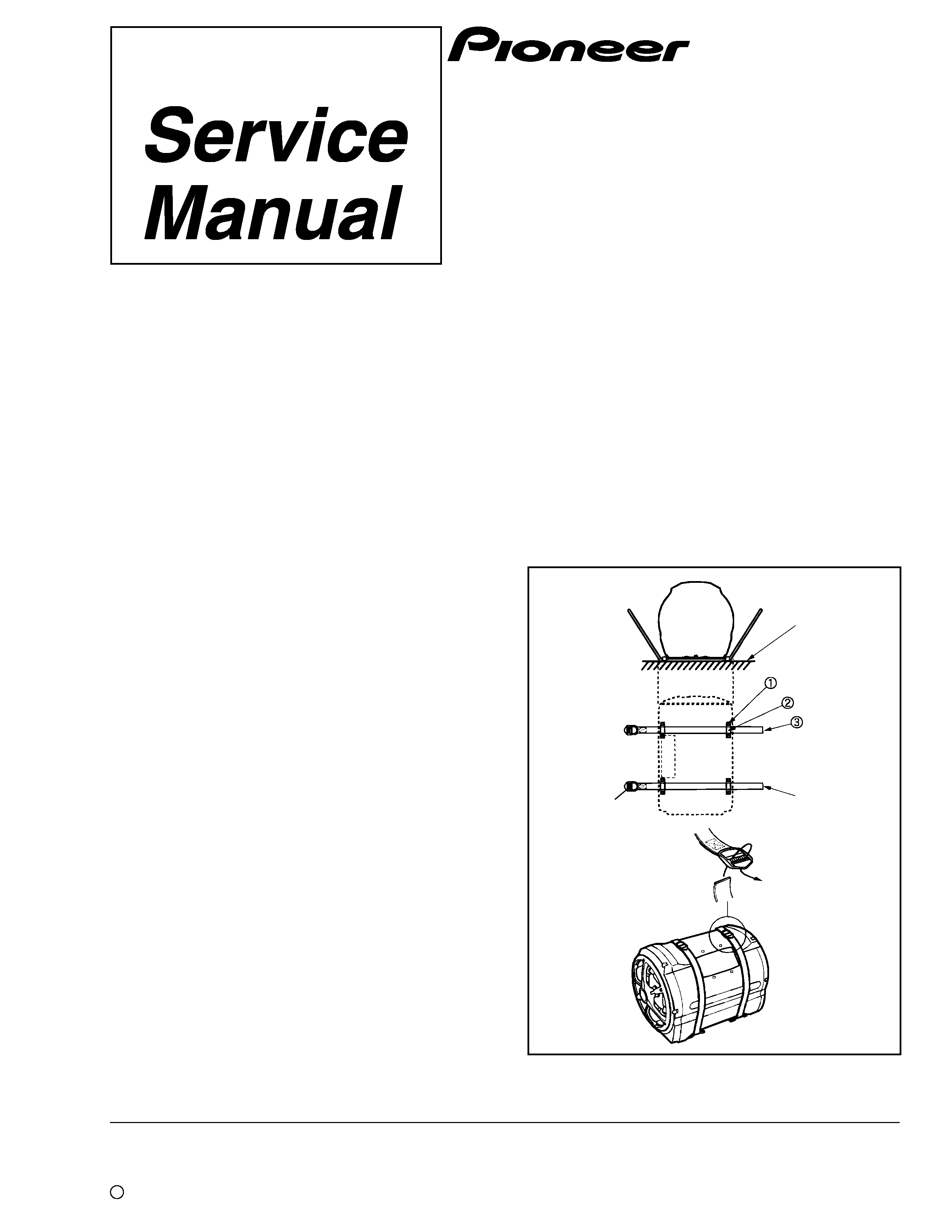
2. HOW TO INSTALL
Iron plate
Belt end
Backle
2
TS-WX20LPA
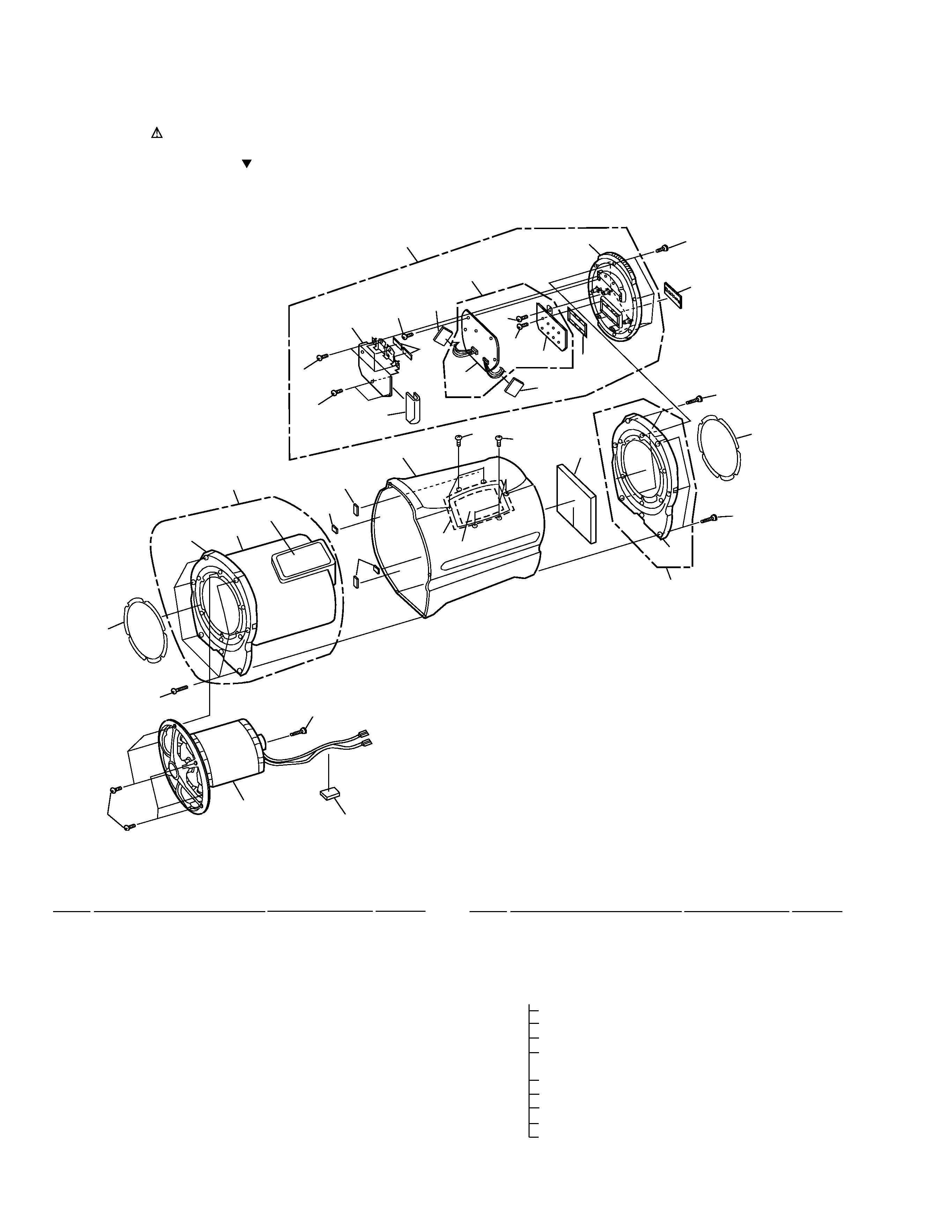
3.1 MAIN UNIT
· MAIN UNIT PARTS LIST
Mark No.
Description
Part No.
Remark
3. EXPLODED VIEWS AND PARTS LIST
NOTES:
· Parts marked by "NSP" are generally unavailable because they are not in our Master Spare Parts List.
· The mark found on some component parts indicates the importance of the safety factor of the part.
Therefore, when replacing, be sure to use parts of identical designation.
· Screws adjacent to mark on the product are used for disassembly.
Mark No.
Description
Part No.
Remark
1
Speaker
20-210AZ
×1
NSP
2
CONTROL UNIT
TWG1013
×1
NSP
3
AMP UNIT
TWH1021
×1
NSP
4
Port
TFX1026
×1
NSP
5
Port Panel
TLM1419
×1
6
Front Baffle Assy
TXL1269
×1
7
Packing
TED1438
×2
8
Top Panel
TLM1418
×1
9
Cabinet
TLM1444
×1
10
Baffle Assy
TXL1273
×2
NSP
11
Baffle
TLM1417
×2
12
Screw
TBA1120
×12
13
Cushion
TED1366
×1
14
Packing
TED1437
×2
15
Sound Absorber
TED1439
×1
16
Packing
TED1442
×1
17
Packing
TED1483
×3
18
Screw
BPH50P250FZK
×15
19
Screw
BPZ40P120FZK
×6
20
AMP Assy
TWZ1016
×1
21
Heat Sink
TNA1509
×1
22
Terminal Panel
TNS1019
×1
23
Screw
BBZ30P080FMC
×20
24
Shield Case
TNA1510
×1
25
Packing
TEB1332
×1
26
Cushion
TED1417
×1
27
Cushion
TED1471
×2
28
Cushion
TEC1416
×2
29
PCB Unit
TWX1024-AZ
×1
4
6
18
12
1
18
16
15
17
17
13
9
19
19
18
2
25
28
26
23
23
28
27
3
23
23
23
21
29
24
12
22
18
7
11
10
8
14
5
7
11
20
×7
×8
3
TS-WX20LPA
1
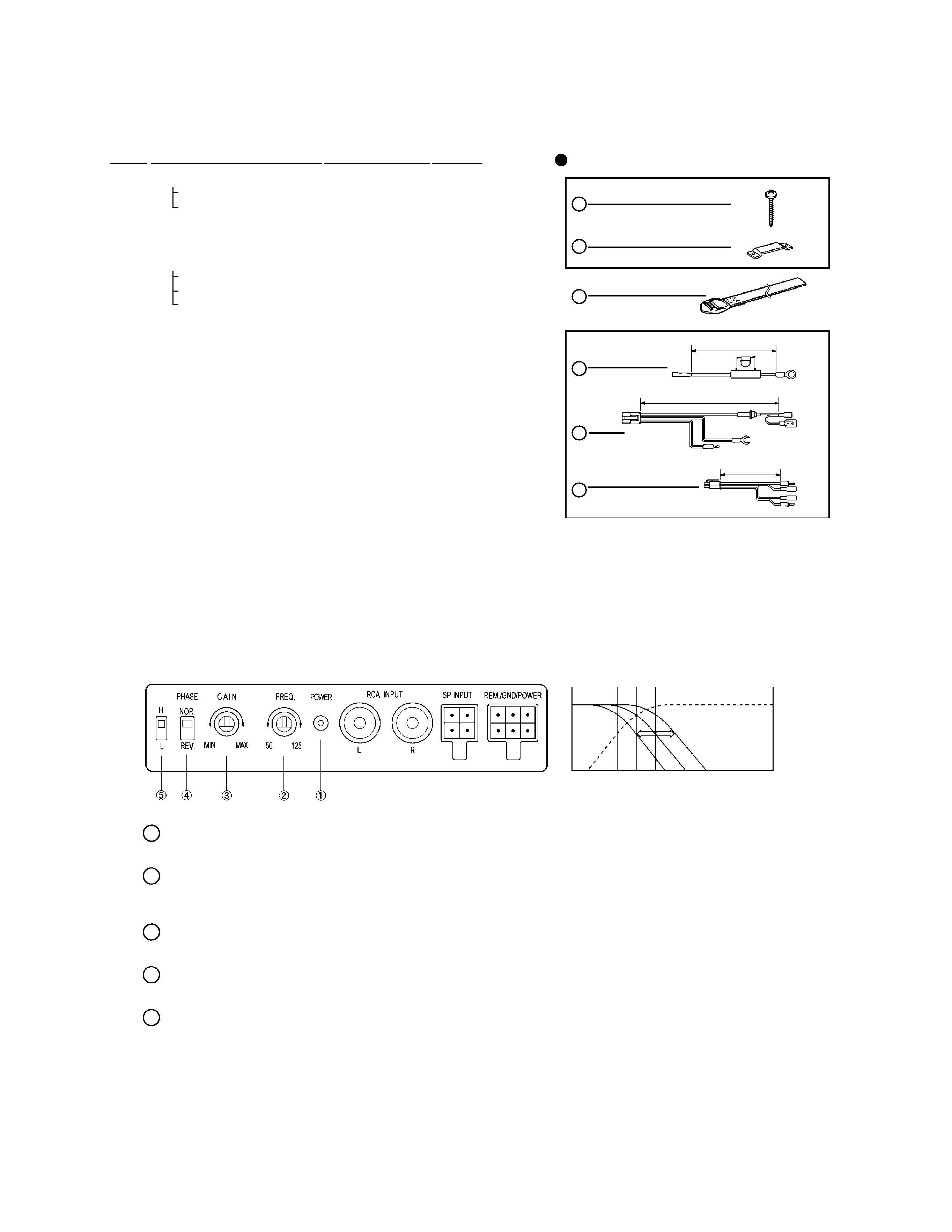
Parts Bag
TEA1272
×1
1-1 Screw
BNC40P250FZK
×8
NSP
1-2 Fitting Metal
TNA1220
×4
2
Belt Assy
TXH1420
×2
NSP
3
Cord Poly. Assy
TXH1572
×1
3-1
Cord
TDC2255
×1
3-2
Cord
TDC2244
×1
3-3
Cord
TDC2245
×1
Operating Instructions
TRD1165
×1
Styrofoam Protector
TEC1902
One pair
Packing Case
THF3333
×1
3.2 PACKING PARTS LIST
×8
×4
×2
×1
×1
×1
1-1
1-2
3-1
3-2
3-3
1
2
3
4
5
6
1
2
3
PARTS INCLUDED
4.8m
5m
25cm
Mark No.
Description
Part No.
Remark
1 Power indicator
Lights up when power is turned on.
2 Frequency control
Turn this knob to change the frequency during sound reproduction. Set the knob to the
bass setting of your choice (continuously variable from 50Hz to 125Hz).
3 Gain control
Use this control to set the desired gain level.
4 Phase switch
Use switch to select the phase according to the system.
5 BFC (Beat Frequency Control) switch
If beating is heard when listening to AM stations on your car radio, change the position of
the BFC switch with a small flat-bladed screwdriver.
CROSSOVER FREQUENCY
Full-range Speaker
Continuously
Variable
50Hz
TS-WX20LPA
80Hz 125Hz
4. CONTROLS AND THEIR USE
4
TS-WX20LPA
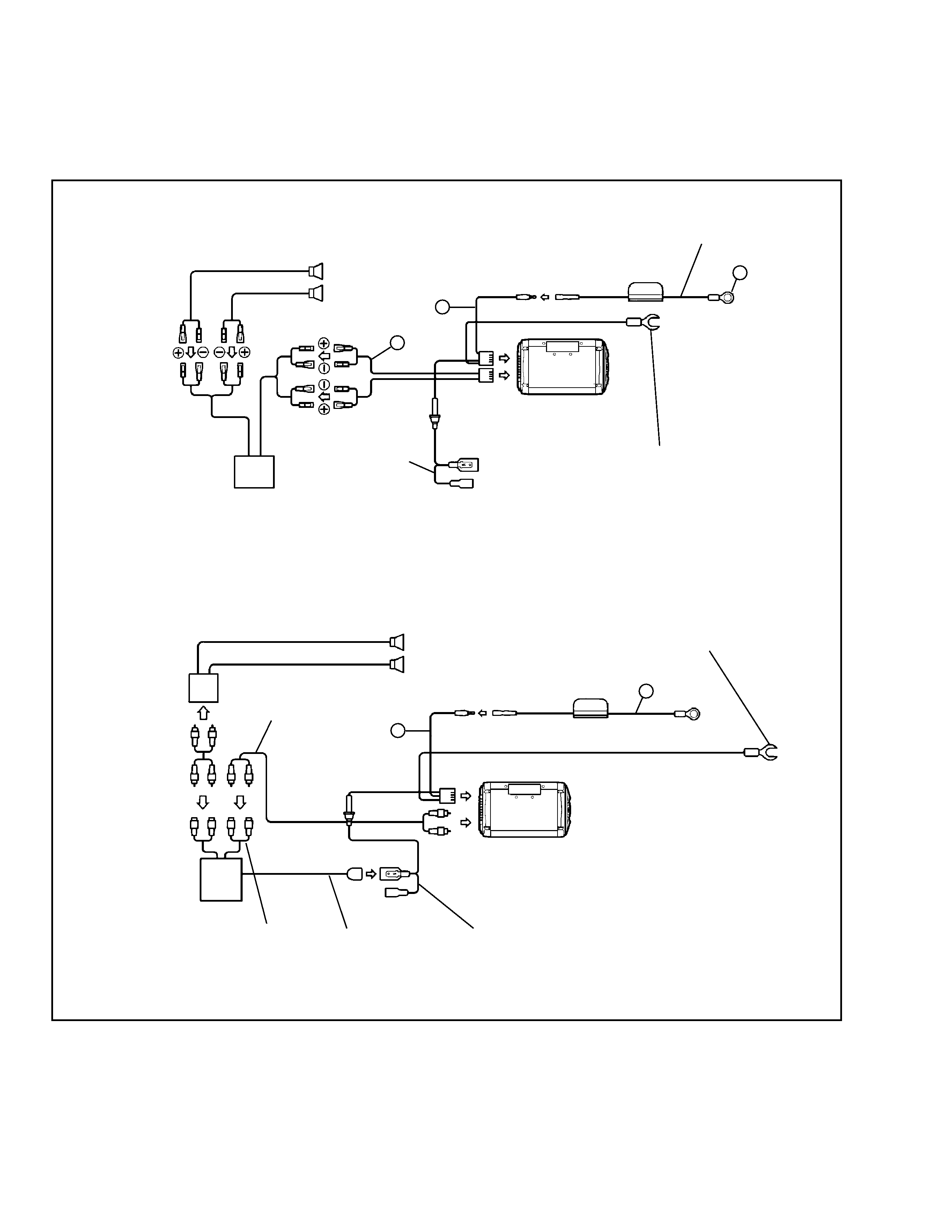
Wiring Example 1 (Speaker line Input system)
Wiring Example 2 (RCA Input system)
Speaker
Speaker
0.5A
0.5A
Speaker
line input
15A
15A
TS-WX20LPA
TS-WX20LPA
For ground
For ground
Black
Blue
Blue
System remote
control output
RCA preout
RCA cord (Not included)
When using the speaker line input, be sure to connect the
cord to the lead of the accessory power cord.
Connect all the other leads, and finally connect
this terminal to the positive (+) terminal of the
battery.
Connect firmly to a metal part of the car body.
Improper grounding will cause this unit to
operate abnormally.
Connect firmly to a metal part of the car body.
Improper grounding will cause this unit to
operate abnormally.
System remote control input cord (blue cord included) supplies
power to your unit, determining whether it is ON or OFF.
Wire the cord to the system remote control output of your deck, etc.
Car stereo
Deck, etc.
Power
amplifier
4
5
6
4
5
5. CONNECTIONS
TS-WX20LPA
5
A
B
C
D
1
23
4
1
2
3
4
Note : When ordering service parts, be sure to refer to "EXPLODED VIEWS and PARTS LIST" or "PCB PARTS LIST".
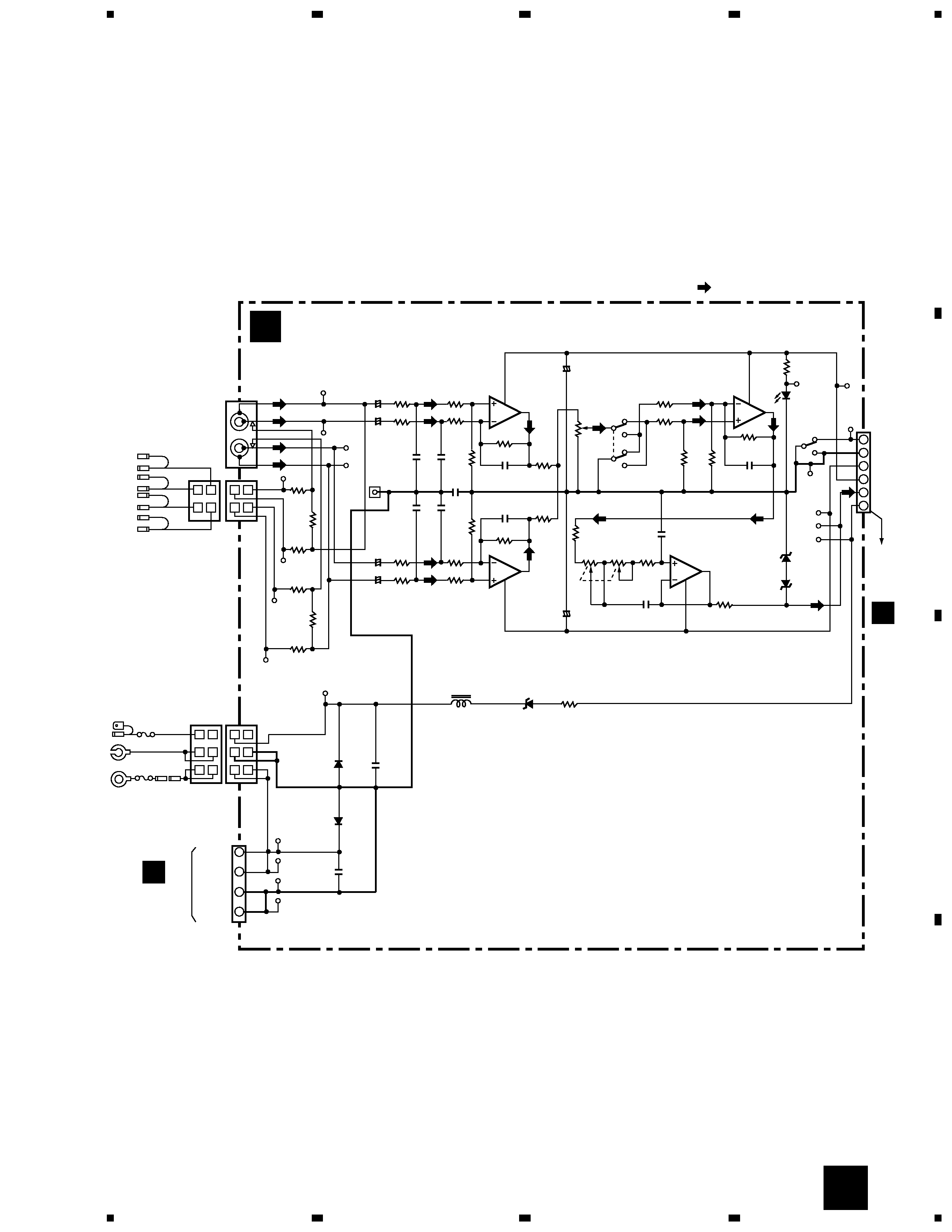
6. PCB UNIT(TWX1024-AZ)
6.1 SCHEMATIC DIAGRAM
6.1.1 CONTROL UNIT
4
3
2
1
CN104
CN105
4
5
6
3
2
1
R124
6.2k
R123
12k
C109
0.15
20k
VR102
20k
R116
2.2k
C106
100p
R114
20k
R130
10k
R129
10k
SW101
BFC
SW
Sig.G
-15.4V
+15.4V
Sig.
REMOTE
BFC
GAIN
VR101
5k
8
5
7
6
2
1
4
3
R128
1k
D103
2
5
4
3
IC101
(2/2)
IC101
(1/2)
IC102
(1/2)
C108
0.068
R122
12k
Nor
Rev
SW102
C113
47/16
R113
20k
R115
2.2k
C105
100p
C118
0.1
C110
0.001
(EMI)
C111
0.001
(EMI)
C114
0.001
(EMI)
C115
0.001
(EMI)
+
C112
47/16
+
1
9
7
6
IC102
(2/2)
R120
150k
R119
8.2k
R118
30k
C107
100p
R126
300k
R112
20k
R111
20k
C102
1/50
(NP)
C104
1/50
(NP)
R117
10k
R125
10k
R107
10k
R109
10k
R108
10k
R110
10k
R101
2.2k
R105
240
R106
240
C101
1/50
(NP)
C103
1/50
(NP)
R103
2.2k
R102
2.2k
R104
2.2k
R121
30k
BUFFER
POWER IND.
PHASE
ISOLATOR
LOWPASS FILTER
TP102
TP103
TP104
FG101
TP101
TP126
TP111
TP112
TP113
TP115
TP116
TP105
TP106
TP107
TP108
TP125
TP121
TP122
TP123
TP124
2
1
4
3
2
1
4
3
2
1
4
3
6
5
2
1
4
3
6
5
R127
10k
IC101,IC102
UPC4570H
D101
GP30DL-6372
D102
ERA15-02VH
D103
RD6R8JS
D104
SLH-34VC3F
D105,D106
RD4R3ES
D104
L101
10mH
(EMI)
C117
0.1
D102
D106
D105
C116
0.1
D101
REMOTE
GND
REMOTE
GND
BACKUP
+DC14,.4V
BACKUP
BACKUP
GND
GND
CN101
CN102
CN103
RCA INPUT
SP INPUT
L+
L
R
R+
0.5A
15A
TP114
A CONTROL UNIT
(TWG1013)
CN201
B
CN202
B
: AUDIO SIGNAL ROUTE
A
