ORDER NO.
PIONEER CORPORATION 4-1, Meguro 1-chome, Meguro-ku, Tokyo 153-8654, Japan
PIONEER ELECTRONICS (USA) INC. P.O. Box 1760, Long Beach, CA 90801-1760, U.S.A.
PIONEER EUROPE NV Haven 1087, Keetberglaan 1, 9120 Melsele, Belgium
PIONEER ELECTRONICS ASIACENTRE PTE. LTD. 253 Alexandra Road, #04-01, Singapore 159936
PIONEER CORPORATION 2007
S-Z9
RRV3668
SPEAKER SYSTEM
S-Z9
XTW/UC
1. REASSEMBLY AND DISASSEMBLY PRECAUTIONS
1.1 SPEAKER
1.2 NETWORK
The grille is attached to the cabinet by 4 external catches. To
detach by pulling it toward you.
The speaker unit(MID&TW) is attached to the cabinet by 4
external screws, speaker unit(WF) is attached to the cabinet by
6 external screws. To detach it, first unfasten those screws.
Next remove the cabinet. Then remove the cable. When attaching
it, face its terminal downward(WF). When attaching it, face its
terminal upward(MID&TW).
The network Assy is attached to the cabinet back by 4 screws.
To detach it, first remove the cord connected with the speaker unit.
Next remove the cord connected with the input terminal. And then
take out the screws.
To attach it once again, attach the network assy to the cabinet back
by 4 screws. Next connect the cord to the input terminal. At this
time connect the minus side of woofer and the plus side of tweeter
directly to the minus side of input terminal.
And then attach the cord to the speaker unit.
T-ZZR AUG 2007 Printed in Japan

S-Z9
2
12
3
4
12
3
4
C
D
F
A
B
E
2. EXPLODED VIEWS AND PARTS LIST
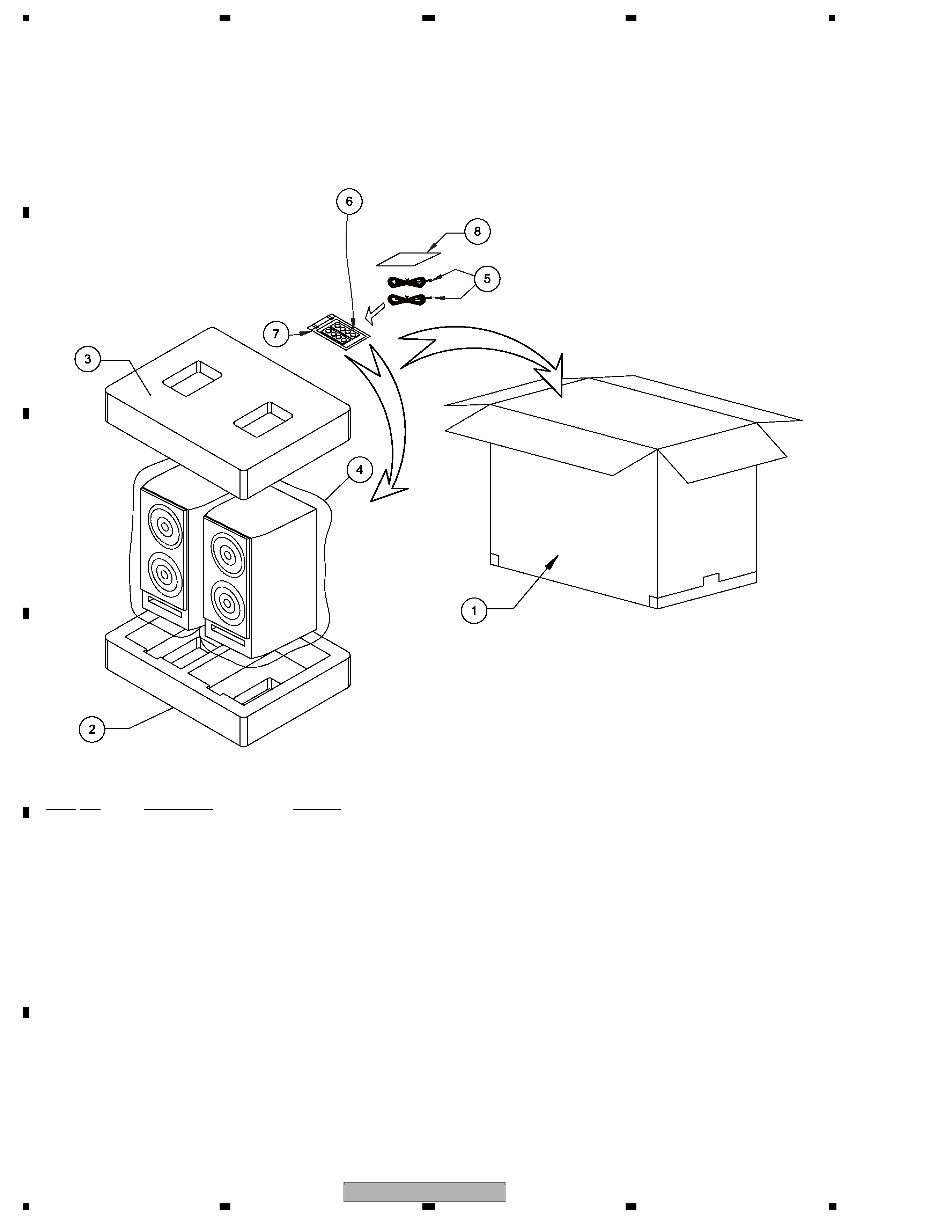
2.1 PACKING
PACKING Parts List
NOTES : · Parts marked by " NSP " are generally unavailable because they are not in our Master Spare Parts List.
· The
> mark found on some component parts indicates the importance of the safety factor of the part.
Therefore, when replacing, be sure to use parts of identical designation.
Pionee
r
Pio
neer
(Insertion point is back plane of speaker.)
FRONT
Mark No.
Description
Part No.
1
Packing Case
390-03140004
2
Protector (Bottom)
370-031400B0
3
Protector (Top)
370-031400T0
4
Protection Sheet
153-06555050
5
Speaker Wire
230-02566002
6
Non Skid Pad
450-06440003
7
Polyethylene Bag S1
380-13009012
8
Cleaning Cloth
155-01923001

S-Z9
3
56
7
8
56
7
8
C
D
F
A
B
E
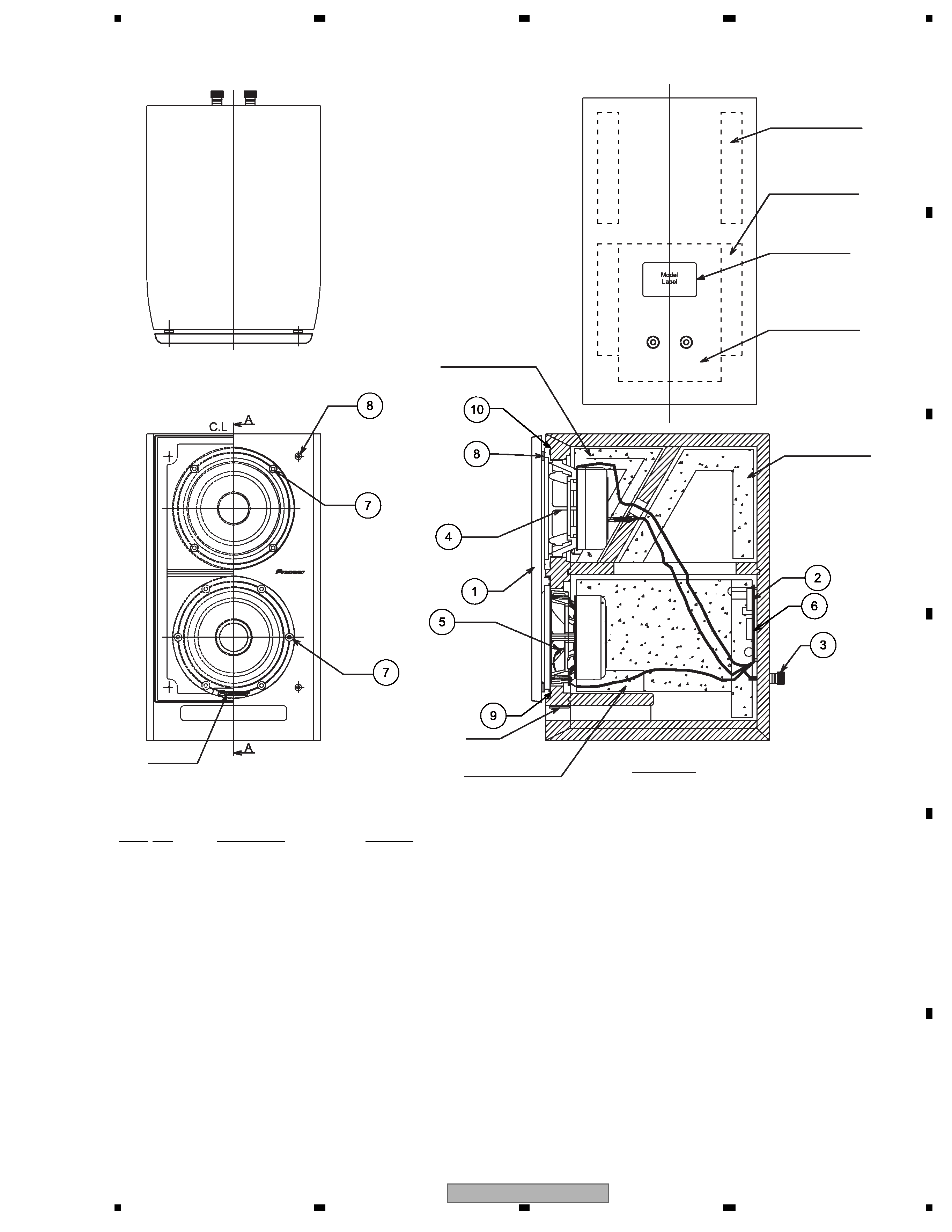
2.2 SPEAKER SYSTEM (CS ASSY R)
SPEAKER SYSTEM Parts List
Model Label
Acoustic Absorbent
Acoustic Absorbent
Acoustic Absorbent
Acoustic Absorbent
Acoustic Absorbent
Acoustic Absorbent
Section A-A
Felt
Badge
Mark No.
Description
Part No.
1
Grille Assy
889-02650002
2
Network Assy
889-02650003
3
Input Terminal
320-09000056
4
Speaker (for Mid & Tweeter)
W13FR80-54FX
5
Speaker (for Woofer)
W12LR90-51C
6
Screw (for Network Assy)
250-3516305
7
Screw (for Speaker)
250-4020862
8
Catch (for Cabinet)
307-10000003
9
Gasket (for Woofer)
312-14711610
10
Gasket (for Tweeter)
312-14711710

S-Z9
4
12
3
4
12
3
4
C
D
F
A
B
E
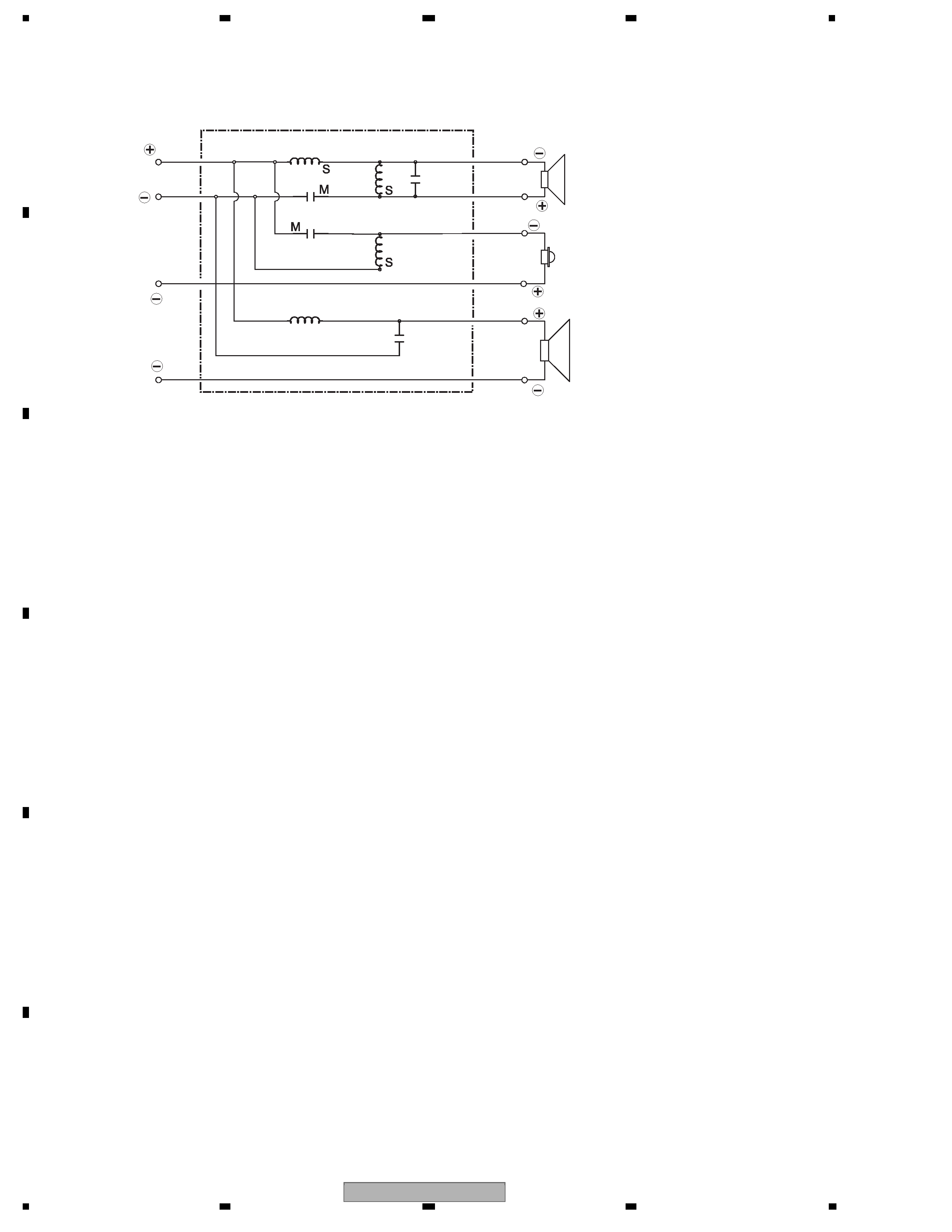
3. SCHEMATIC DIAGRAM
Red
INPUT
Woofer
Midrange
Tweeter
Clear
Clear
Clear
Red
Green
Clear
Clear
Yellow
Network Assy (889-02650003)
4.7 uF / 100 V
3.9 uF / 100 V
2.2 uF / 100 V
47 uF / 50 V
1.8 mH
3.0 mH
1.5 mH
0.19 mH
