ORDER NO.
PIONEER CORPORATION 4-1, Meguro 1-chome, Meguro-ku, Tokyo 153-8654, Japan
PIONEER ELECTRONICS (USA) INC. P.O. Box 1760, Long Beach, CA 90801-1760, U.S.A.
PIONEER EUROPE NV Haven 1087, Keetberglaan 1, 9120 Melsele, Belgium
PIONEER ELECTRONICS ASIACENTRE PTE. LTD. 253 Alexandra Road, #04-01, Singapore 159936
PIONEER CORPORATION 2008
S-IC621D
RRV3861
T-ZZR SEP. 2008 Printerd in Japan
IN-CEILING SPEAKER
S-IC621D
/XTM/UC
S-IC821D /XTM/UC
This service manual is intended for qualified service technicians; it is not meant for the casual
do-it-yourselfer. Qualified technicians have the necessary test equipment and tools, and have been
trained to properly and safely repair complex products such as those covered by this manual.
Improperly performed repairs can adversely affect the safety and reliability of the product and may
void the warranty. If you are not qualified to perform the repair of this product properly and safely,
you should not risk trying to do so and refer the repair to a qualified service technician.
WARNING
This product contains certain electrical parts contain chemicals which are known to the State of California to cause cancer,
birth defects or other reproductive harm.
Health & Safety Code Section 25249.6 - Proposition 65

2
S-IC621D
12
3
4
C
D
F
A
B
E
1
23
4
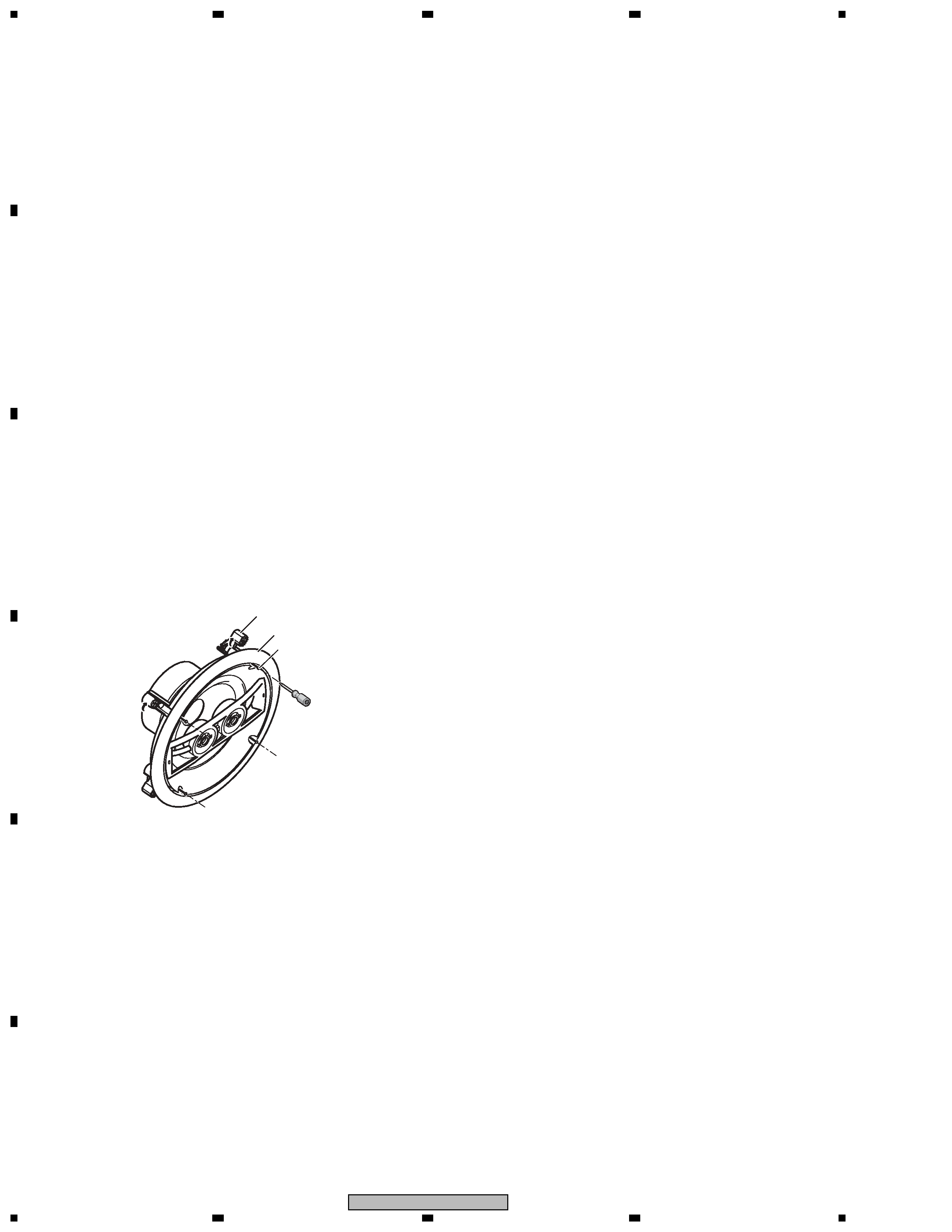
1. REASSEMBLY AND DISASSEMBLY PRECAUTIONS
· The grille is inserted into the baffle. To detach it, insert a grill
removal tool into each of the 4 corner holes of the grille net and
pull it out carefully.
· The sub frame is attached to the baffle frame by 4 external
screws. To detach it, unfasten those screws.
· The crossover networks is attached to the speaker frame by 3
external screws. To detach them, first disconnect the speaker's
wires.
Next remove the speaker frame. Then unfasten those screws.
· The tweeter are inserted between the bridge and Tw (Tweeter).
rear housing. The bridge assy is attached to the baffle frame by 4
external screws.
To detach it, unfasten those screws. When reattaching it, fit the
boss of the bridge assy into the hole on the baffle frame.
· The woofers is attached to the baffle frame by 4 external screws.
To detach it, unfasten those screws. When re-attaching it,
face
its terminal downward.
· Attach the speaker frame to the wall /ceiling, and
tighten the screws lightly (temporary attachment).
At this point the rotating clamp will rotate so that the rotating
clamp and frame are clamped on to the wall/ceiling.
Gently try pulling the speaker forward and check that all of the
rotating clamps have rotated outwards and are lightly clamping
to the wall/ceiling.
· Adjust the mounting orientation for the primary
listening position.
· Tighten the screws firmly using no more than the
maximum torque specified.
Allowable maximum torque: 1.0 N.m
Screw
Speaker frame
Rotating clamp

3
S-IC621D
5
67
8
5
6
7
8
C
D
F
A
B
E
(1/2)
(1/2)
(2/2)
(2/2)
Serial No. Label
2. EXPLODED VIEWS AND PARTS LIST
Parts marked by "NSP" are generally unavailable because they are not in our Master Spare Parts List.
The
mark found on some component parts indicates the importance of the safety factor of the part.
Therefore, when replacing, be sure to use parts of identical designation.
NOTES:
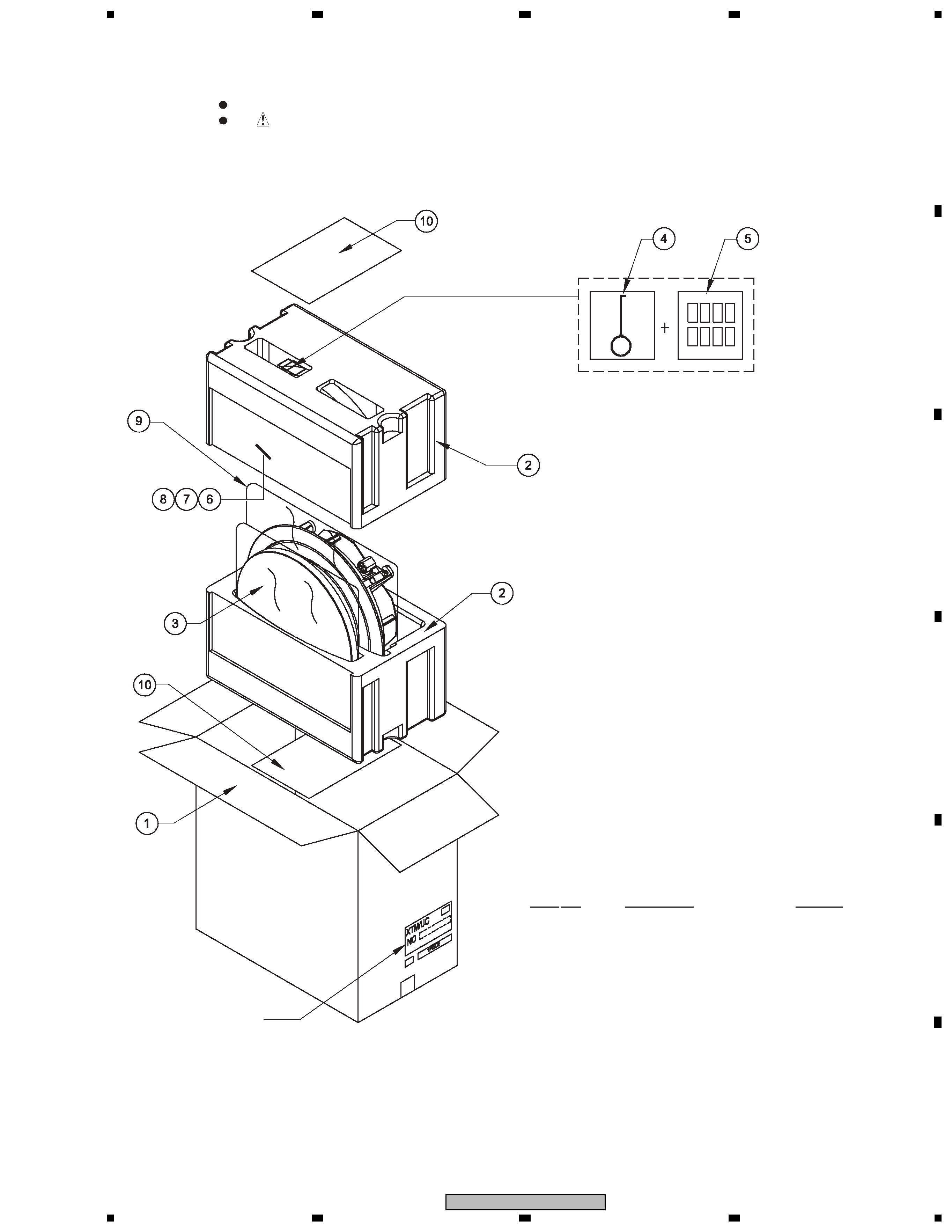
2.1 PACKING
1
Packing Case
(for S-IC621D)
CB16084
(for S-IC821D)
CB20041
2
Protector (for Top & Bottom)
PL16057
3
Grille Assy
S160M072-F4
4
Accessories Set (Removal Tool)
SFAP001-F4
5
Accessories Set (Adhesive Tape)
SFAP002-F4
NSP 6
Warranty Card
SRY1049
7
Operating Instruction
SRD1383
(English/French)
8
Template
IM163
9
Polyethylene bag (for CS)
PE019191
10
Inner Pad
IP160109
PACKING Parts List
Mark No.
Description
Part No.

4
S-IC621D
12
3
4
C
D
F
A
B
E
1
23
4
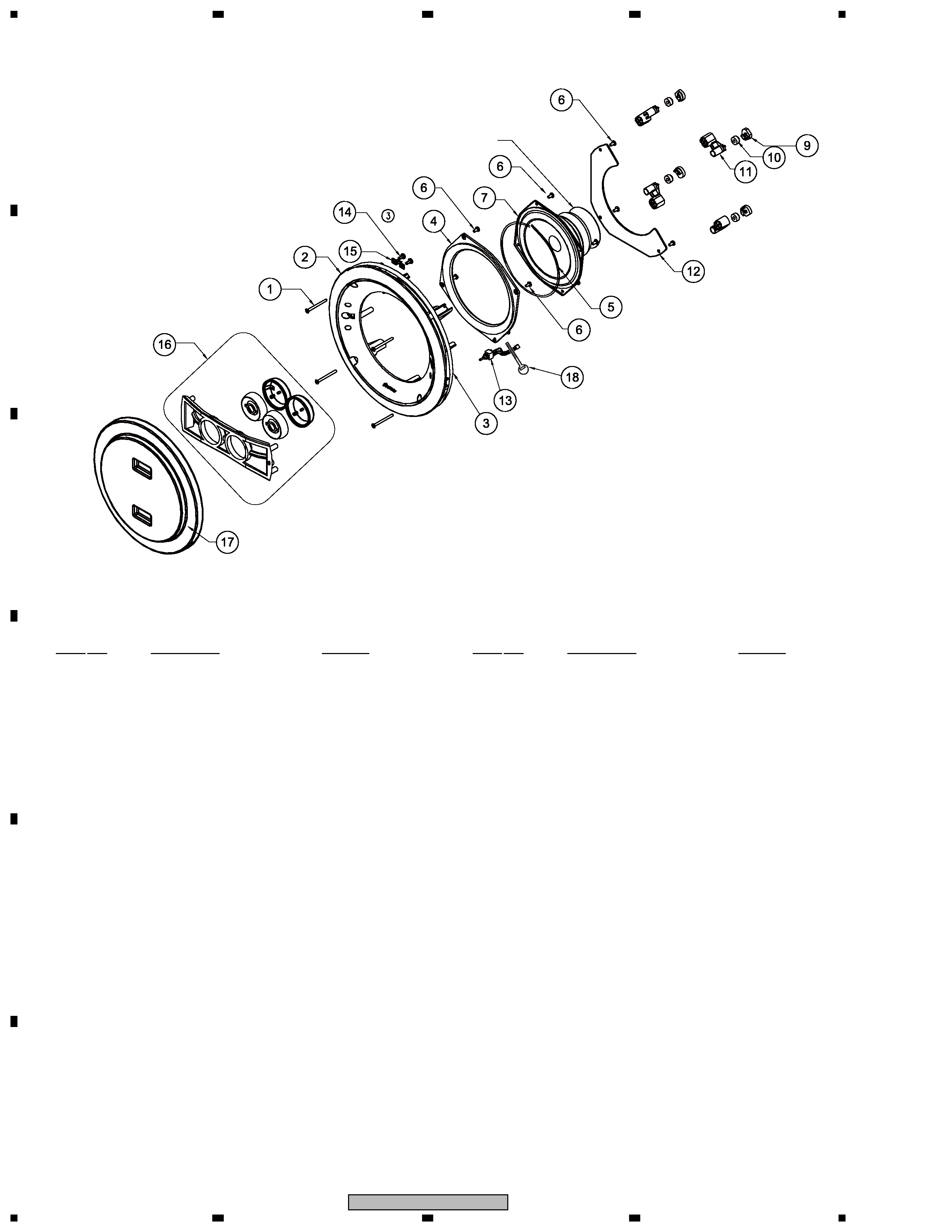
2.2 CS ASSY
Model Label
1
Screw (for Install Nail)
SC045042
2
Baffle Frame
FP15
3
Packing
PK263
4
Sub Frame (for S-IC621D)
BK100
5
Packing (for S-IC621D)
PK261
6
Screw
SC040733
7
Speaker
(for S-IC621D)
C16ER85-52F
(for S-IC821D)
B20ER85-52F
8
- - - - - - - - - - - - -
- - - - - - -
9
Nail Stopper
BK99
10
Cushion
RF18
11
Install Nail
BK101
12
Network Assy
(for S-IC621D)
CR59
(for S-IC821D)
CR58
13
Level Control Assy (for HF)
SCA003-F4
14
Screw (for Bracket)
SC031042
15
Bracket
BK104
16
Bridge Assy
STW050-F4
17
Paint Mask
CV16055
18
Lock Tie
CA110801
CS Assy Parts List
Mark No.
Description
Part No.
Mark No.
Description
Part No.

5
S-IC621D
5
67
8
5
6
7
8
C
D
F
A
B
E
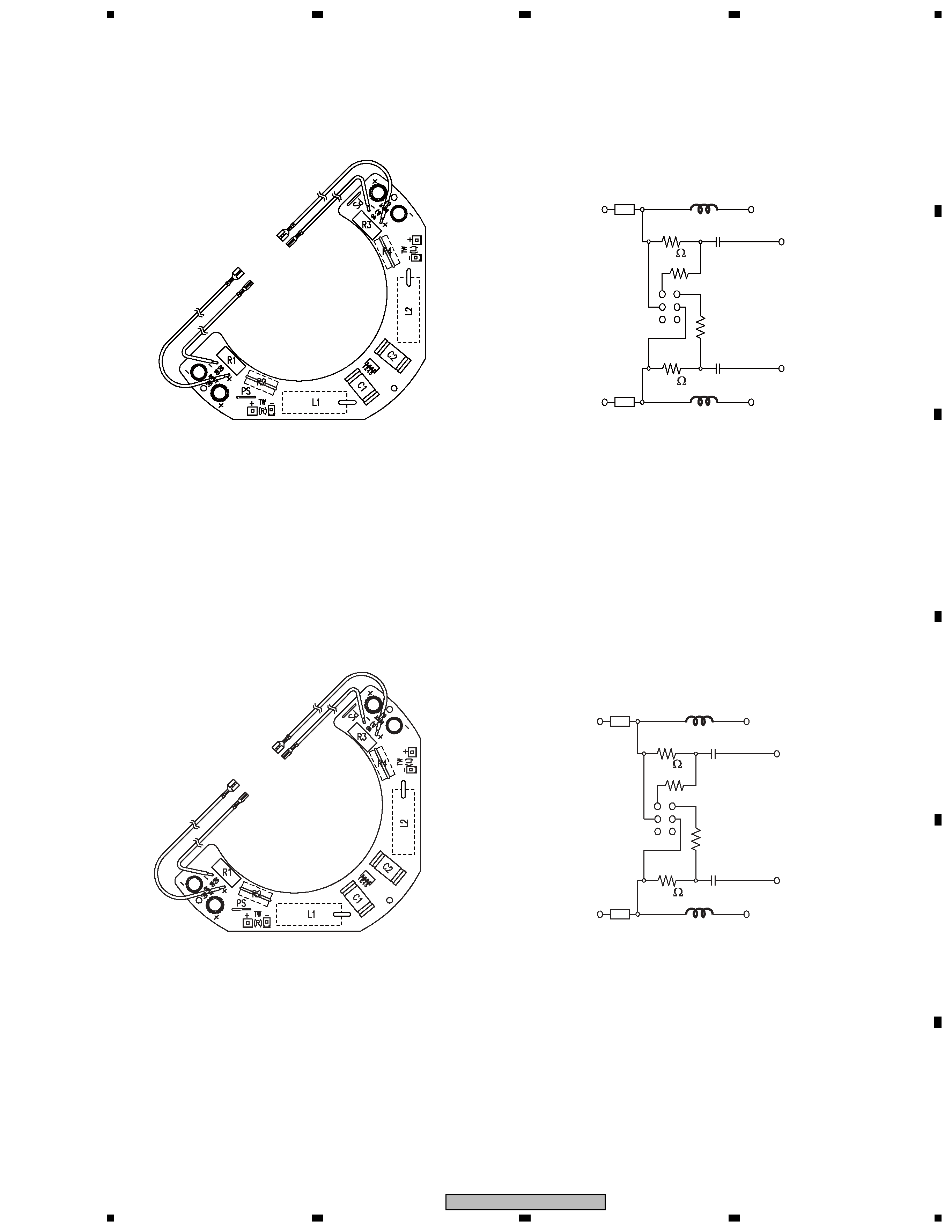
3. SCHEMATIC DIAGRAM
3.1 NETWORK ASSY
[1] Network Assy (CR59)
[2] Network Assy (CR58)
ON-OFF or
ON-ON
-
+
+
poly switch
2
1
C1
R1
-
+
+
poly switch
5
4
C2
R3
R-CH
L-CH
Right Wf +
Left Wf +
Right Tw -
Left Tw -
3
6
L1
R2
R4
L2
to be shorted
to be shorted
3.9 uF / 100 V
to be shorted
to be shorted
3.9 uF / 100 V
RF-RM135
RF-RM135
P.SW: (RF-RM135 : rated 60 V)
P.SW has extreme positive resistance-temperature characteristics.
If an abnormal current flows to P.SW due to an excessive input or
unusual signal, P.SW heats up and the resistance rapidly increases.
With this function, the speakers are protected from excessive input
or unusual signal. The resistance value increases even when using
a soldering iron for repairing, so allow it to cool before using.
4.7
4.7
Ref
er-
(CA115822)
x2
UL
1007
A
WG16
# 205,
T :
0.5
mm
(RED)
150mm
Ref
er-
(CA115823)
x2
UL
1007
A
WG16
#
110,
T :
0.5mm
(BLK)
150mm
to be shorted
to be shorted
3.9 uF / 100 V
to be shorted
to be shorted
3.9 uF / 100 V
RF-RM135
RF-RM135
ON -OFF or
ON -ON
-
+
+
poly switch
2
1
C1
R1
-
+
+
poly switch
5
4
C2
R3
R-CH
L-CH
Right Wf +
Left Wf +
Right Tw -
Left Tw -
3
6
L1
R2
R4
L2
Ref
er-
(CA11
5822)
x2
UL
1007
A
WG16
#
205,
T :
0.5mm
(RED)
150mm
Ref
er-
(CA115823)
x2
UL
1007
A
WG16
# 110
,
T :
0.5
mm
(BLK)
150mm
P.SW: (RF-RM135 : rated 60 V)
P.SW has extreme positive resistance-temperature characteristics.
If an abnormal current flows to P.SW due to an excessive input or
unusual signal, P.SW heats up and the resistance rapidly increases.
With this function, the speakers are protected from excessive input
or unusual signal. The resistance value increases even when using
a soldering iron for repairing, so allow it to cool before using.
3.3
3.3
