Operating Instructions
PROJECTION MONITOR RECEIVER
SD-641HD5

2
<ARB1526>
Progressive Scan/HDTV READY
Dual System Component Input for NTSC/
Progressive
Connection to a DVD player with a component output terminal
makes possible high-picture-quality display superior to that of
S-VIDEO terminal connection. Also handles high resolution
component input (1080i, 480p), which will function as an
interface for high-quality images in future.
DUAL TUNER (SPLIT screen and SEARCH
screen function)
Two TV tuners are provided, making it possible to split the
screen vertically in two and display moving images
simultaneously on them. In addition, the channel search
function makes it possible to check, etc., on the program in the
back. Its convenience will be limited only by your imagination.
Fully Illuminated Remote Control Unit
A fully illuminated universal remote control is used that makes
it possible to operate other devices. Remote operations can
thus be performed easily even in dark rooms and similar
environments.
SURROUND
*
Natural front surround sound (SRS) with an expansive feel
and natural sound similar to multi-channel surround sound
(TruSurround) can be enjoyed.
Highly Detailed Image Display Technology
The tinted 0.52mm ultrafine-pitch screen, Hi Band Video
Amplifier circuit, Progressive contour correction circuit and
various other technologies for creating high picture quality
make the display of highly detailed images possible.
Lens System for HDTV
Adoption of a lens system for high-resolution HDTV that
faithfully reproduces HDTV 1080i signals allows highly color-
saturated images to be displayed at high resolution.
Whole Screen IR Receiver
The remote control sensor is installed behind the screen,
allowing you to operate this monitor with the remote control
unit in those installations where only the screen is revealed.
3D Y/C Separation Circuit
This three-dimensional Y/C separation circuit reproduces
clearer picture quality.
Scan Velocity Modulation Circuit
Precise images from progressive scanning can be displayed
in even greater detail, owing to the Scan Velocity Modulation
(SVM) circuit.
Nine-Point Convergence System
Convergence adjustment of not only the center but 8
surrounding points makes it possible to display clear images
with no color distortion around the screen.
FEATURES
Read and understand these 'Operating
Instructions' before operating your Monitor.
Follow
the
'IMPORTANT
SAFETY
INSTRUCTIONS AND WARNINGS' section and
all the warnings on the product.
* TruSurround, SRS and the SRS symbol are trademarks of
SRS Labs, Inc. TruSurround and SRS are incorporated under
a license from SRS Labs, Inc. Patented in the U.S. and
selected countries.

<ARB1526>
3
INTRODUCTION
Information to User
Alteration or modifications carried out without appropriate authorization may invalidate the user's right to operate the equipment.
Thank you for purchasing this PIONEER Projection Monitor
Receiver.
Please read the precautionary instructions enclosed with these
operating instructions please do so before proceeding.
After learning how to operate the Projection Monitor, be sure
to keep this manual handy for future reference.
IMPORTANT NOTICE
The model number and the serial number of this Projection
Monitor are located on the rear panel.
Please write the serial number on the enclosed warranty card
and keep it in a safe place for future reference.
In this manual, we refer to the 'PROJECTION MONITOR
RECEIVER', as the 'Projection Monitor' or the 'Monitor'.
Note on the SPLIT screen and SEARCH screen functions
The SPLIT screen and SEARCH screen functions provided in
this monitor are intended for private viewing only.
Use of the above video processing functions for profitmaking
purpose or for public viewing (clubs, hotels, etc.) without prior
authorization from the transmitter and/or owner of the video
program (s) may be an infringement of existing copyright laws.
WARNING:
TO REDUCE THE RISK OF THE FIRE OR
ELECTRIC SHOCK, DO NOT EXPOSE THIS
APPLIANCE TO WET LOCATIONS.
CAUTION:
TO PREVENT ELECTRIC SHOCK DO NOT USE THIS
(POLARIZED) PLUG WITH AN EXTENSION CORD,
RECEPTACLE OR OTHER OUTLET UNLESS THE BLADES CAN
BE FULLY INSERTED TO PREVENT BLADE EXPOSURE.
ATTENTION:
POUR EVITER UNE DECHARGE ELECTRIQUE, NE PAS
UTILISER CETTE PRISE (POLARISEE) AVEC UNE RALLONGE,
UNE PRISE OU UNE AUTRE SORTIE A MOINS QUE LES
LAMES PUISSENT ETRE COMPLETEMENT INTRODUITES ET
NE SOIENT PAS EXPOSEES.
Note to CATV system installer:
This reminder is provided to call the CATV system installer's
attention to Article 820-40 of NEC that provides guidelines for
proper grounding and, in particular, specifies that the cable ground
should be connected to the grounding system of the building, as
close to the point of cable entry as practical.
IMPORTANT
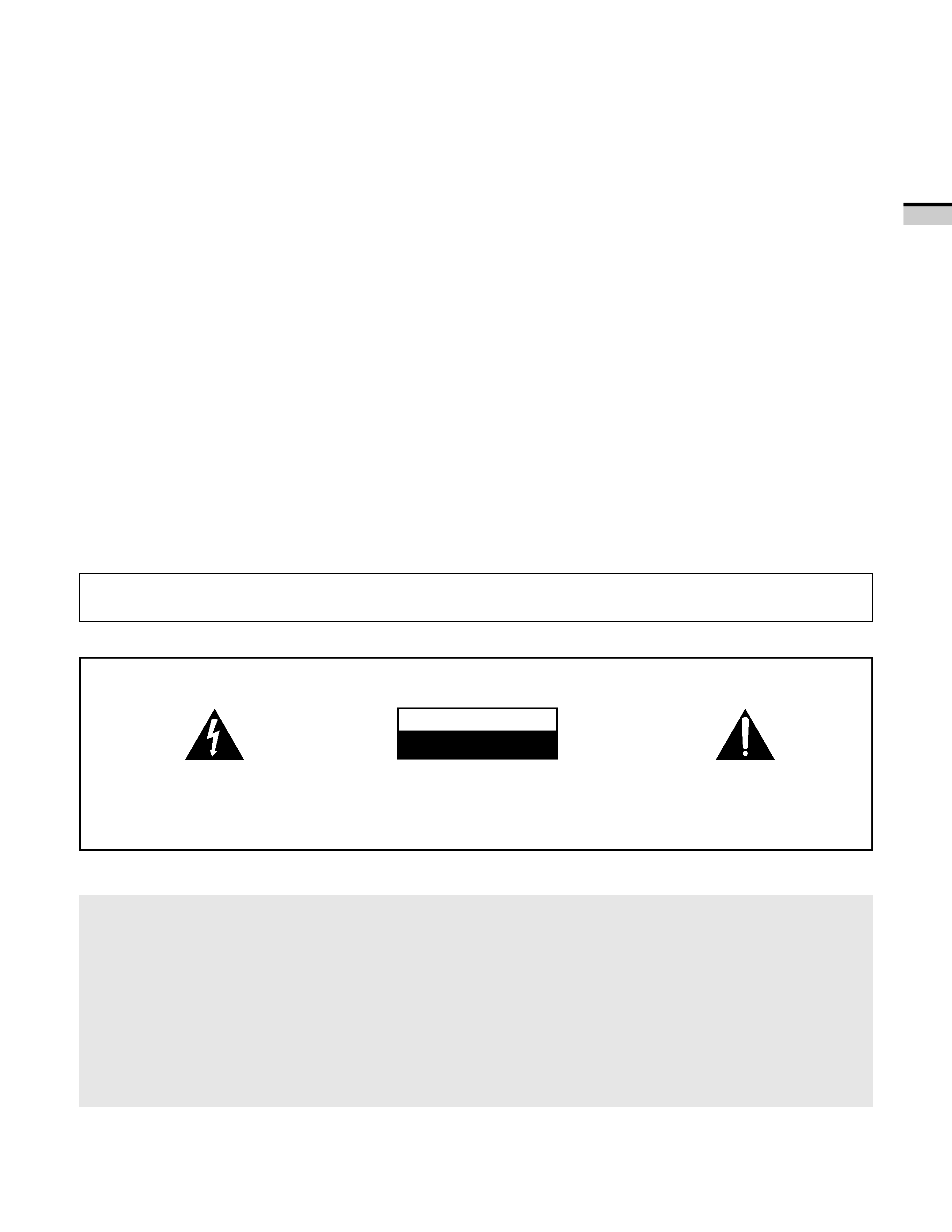
The exclamation point within an equilateral
triangle is intended to alert the user to the presence
of important operating and maintenance
(servicing) instructions in the literature
accompanying the appliance.
CAUTION:
TO PREVENT THE RISK OF ELECTRIC SHOCK, DO
NOT REMOVE COVER (OR BACK). NO USER-SER-
VICEABLE PARTS INSIDE. REFER SERVICING TO
QUALIFIED SERVICE PERSONNEL.
The lightning flash with arrowhead symbol, within
an equilateral triangle, is intended to alert the
user to the presence of uninsulated "dangerous
voltage" within the product's enclosure that may
be of sufficient magnitude to constitute a risk of
electric shock to persons.
RISK OF ELECTRIC SHOCK
DO NOT OPEN
CAUTION
NOTICE ON ADVERSE EFFECTS ON THE TV TUBE
When playing TV games, operating computers or displaying still pictures with your Monitor, be
sure to keep in mind the following points;
1. Select the 'GAME' mode. (Refer to page 18 of the Operating Instructions)
2. Do not use your Monitor for more than two hours.
3. Watch normal TV broadcast's for three times longer than the time of playing TV games, operating
computers or displaying still pictures.
Still patterns can scar the Monitor causing performance damage to the CRT.

4
<ARB1526>
WARNING
IMPORTANT SAFETY INSTRUCTIONS AND WARNINGS
· Read all of these instructions.
· Keep these instructions for later use.
· Follow all warnings and instructions marked on the Monitor.
1.
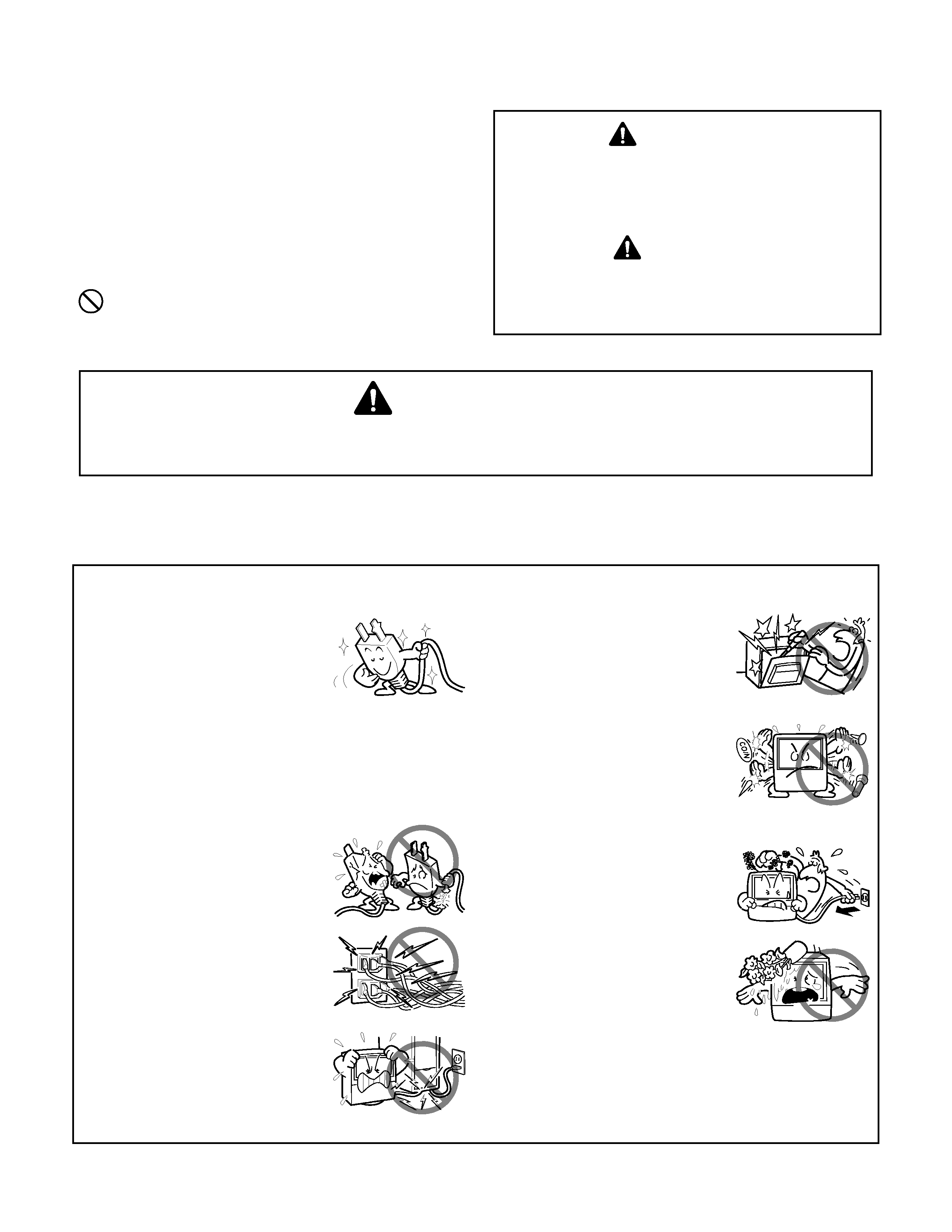
This Monitor is equipped with a
polarized alternating current line
plug (a plug having one blade
wider than the other).
This plug will fit into the power
outlet only one way. This is a
safety feature.
If you are unable to insert the plug
fully into the outlet, try reversing
the plug. If the plug should still fail
to fit, contact your electrician to
replace your obsolete outlet. Do
not defeat the safety purpose of
the polarized plug.
2.
If the power cord or plug becomes
damaged or frayed, unplug this
Monitor from the wall outlet and
refer
to
qualified
service
personnel for servicing.
3.
Do not overload wall outlets and
extension cords as this can result
in fire or electrical shock.
4.
Do not allow anything to rest on
or roll over the power cord, and
do not place the Monitor where
the power cord maybe subject to
traffic or abuse. This may result
in electrical or fire hazard.
5.
Do not attempt to service this
Monitor yourself as opening or
removing covers may expose you
to dangerous voltage or other
hazards. Refer all servicing to
qualified personnel.
6.
Never push the objects of any kind
into this Monitor through cabinet
slots
as
they
may
touch
dangerous voltage points or short
out parts that could result in a fire
or electric shock. Never spill liquid
of any kind on the Monitor.
7.
If the Monitor has been dropped
or the cabinet has been damaged,
unplug this Monitor from the wall
outlet and refer to qualified service
personnel for servicing.
8.
If liquid has been spilled into the
Monitor, unplug the Monitor from
the wall outlet and refer servicing
to qualified service personnel.
The following symbols are found in this
manual and on the labels on the product.
They alert the operators and service
personnel of this equipment to potentially
dangerous conditions.
WARNING
This symbol refers to a hazard or unsafe
practice which can result in severe personal
injury or death.
CAUTION
This symbol refers to a hazard or unsafe
practice which can result in personal injury
or property damage.
This symbol indicates an action that is
prohibited.
FOR YOUR PERSONAL SAFETY

<ARB1526>
5
INTRODUCTION
9.
Do not subject your Monitor to
impact of any kind. Be particularly
careful not to damage the screen
surface.
10.
Unplug the Monitor from the wall
outlet before cleaning. Do not use
liquid cleaners or spray-type
cleaners. Use a damp cloth for
cleaning.
11-1. Do not place this Monitor on an
unstable, uneven or an inclined
location. The Monitor may
overturn, causing serious injury
(to a person), and serious damage
to the appliance.
11-2. Be careful when placing the
Monitor on a cart to move it.
Quick stops, excessive force, and
uneven surfaces may cause the
Monitor and cart to overturn.
12.
· Do not use the Monitor near
water, for example, near a
bathtub, washbowl, kitchen sink,
or laundry tub, in a wet basement,
or near a swimming pool, etc.
· Never expose the Monitor to rain
water.
If the Monitor system has been
exposed to rain or water, unplug
the Monitor from the wall outlet
and refer servicing to qualified
service personnel.
13.
Choose a place where light (artificial
or sunlight) does not shine directly
on the screen.
14.
Avoid dusty places since the
buildup of dust inside the Monitor's
chassis
may
result
in
the
malfunctioning,
when
high
humidity persists.
15.
· The Monitor has slots, or
openings in the cabinet for
ventilation purposes to ensure the
reliable operation of the Monitor,
and to protect it from overheating.
These openings must not be
blocked or covered.
· Nevercovertheslotsoropenings
with cloth or other material.
· Never block the bottom
ventilation slots of the Monitor by
placing it on a bed, sofa, rug, etc.
· Never place the Monitor near or
over a radiator or heat register.
· NeverplacetheMonitorinabuilt-
in enclosure such as a bookcase,
unless proper ventilation is
provided.
PROTECTION AND LOCATION OF YOUR PROJECTION MONITOR RECEIVER
16.
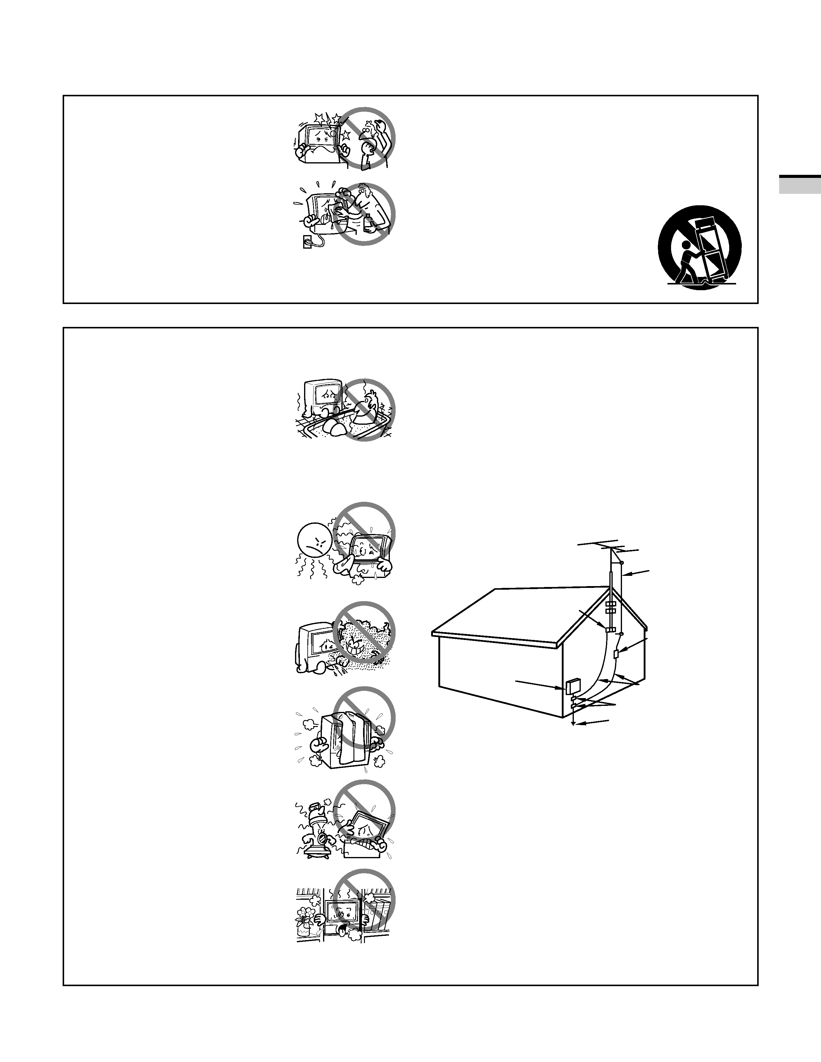
If an outside antenna is connected through other
equipment, be sure the antenna system is grounded so
as to provide protection against voltage surges and built-
up static charges. In the U. S. A., section 810 of the
National Electrical Code, ANSI/NFPA 70, provides
information on proper grounding of the mast and
supporting structure, grounding of the lead-in wire to
an antenna-discharge unit, size of grounding
conductors, location of antenna-discharge unit,
connection to grounding electrode, and requirements
for the grounding electrode.
EXAMPLE OF ANTENNA GROUNDING IN
NATIONAL ELECTRICAL CODE INSTRUCTIONS
ANTENNA
LEAD IN WIRE
ANTENNA
DISCHARGE UNIT
(NEC SECTION 810-20)
GROUNDING CONDUCTORS
(NEC SECTION 810-21)
GROUNDING CLAMPS
POWER SERVICE GROUNDING
ELECTRODE SYSTEM
(NEC ART 250, PART H)
GROUND
CLAMP
ELECTRIC
SERVICE
EQUIPMENT
FIG. A
NEC-NATIONAL
ELECTRICAL CODE
