ORDER NO.
PIONEER ELECTRONIC CORPORATION 4-1, Meguro 1-Chome, Meguro-ku, Tokyo 153-8654, Japan
PIONEER ELECTRONICS SERVICE, INC. P.O. Box 1760, Long Beach, CA 90801-1760, U.S.A.
PIONEER ELECTRONIC (EUROPE) N.V. Haven 1087, Keetberglaan 1, 9120 Melsele, Belgium
PIONEER ELECTRONICS ASIACENTRE PTE. LTD. 253 Alexandra Road, #04-01, Singapore 159936
PIONEER ELECTRONIC CORPORATION 1999
WPWXJ
AC220240V
RDXJ
AC110127V/220240V
With the voltage selector
MULTI COMPACT DISC PLAYER
RRV2122
TZZR APR. 1999 Printed in Japan
PD-M427
CONTENTS
1. SAFETY INFORMATION .................................... 2
2. EXPLODED VIEWS AND PARTS LIST ............. 4
3. SCHEMATIC DIAGRAM ................................... 10
4. PCB CONNECTION DIAGRAM ....................... 14
5. PCB PARTS LIST ............................................. 18
6. ADJUSTMENT .................................................. 21
7. GENERAL INFORMATION .............................. 29
7.1 DISPLAY .................................................... 29
7.2 BLOCK DIAGRAM ...................................... 30
8. PANEL FACILITIES AND SPECIFICATIONS
................................................................... 31
THIS MANUAL IS APPLICABLE TO THE FOLLOWING MODEL(S) AND TYPE(S).
'
7
6
6
MULTI COMPACT DISC PLAYER
STANDBY/ON
DISC
TRACK
MIN
SEC
1-BIT¥DLC DIRECT LINEAR CONVERSION
EJECT
REPEAT PROGRAM
DISC
TRACK/MANUAL
RANDOM
HI--LITE
STOP
PLAY/PAUSE
-DISC
MULTI CD
0
41
¢
¡
PD-M407
Model
PD-M427
PD-M407
Type
Power Requirement
The voltage can be converted by
the following method.

PD-M427, PD-M407
2
WPWXJ type Only
REAR
IMPORTANT
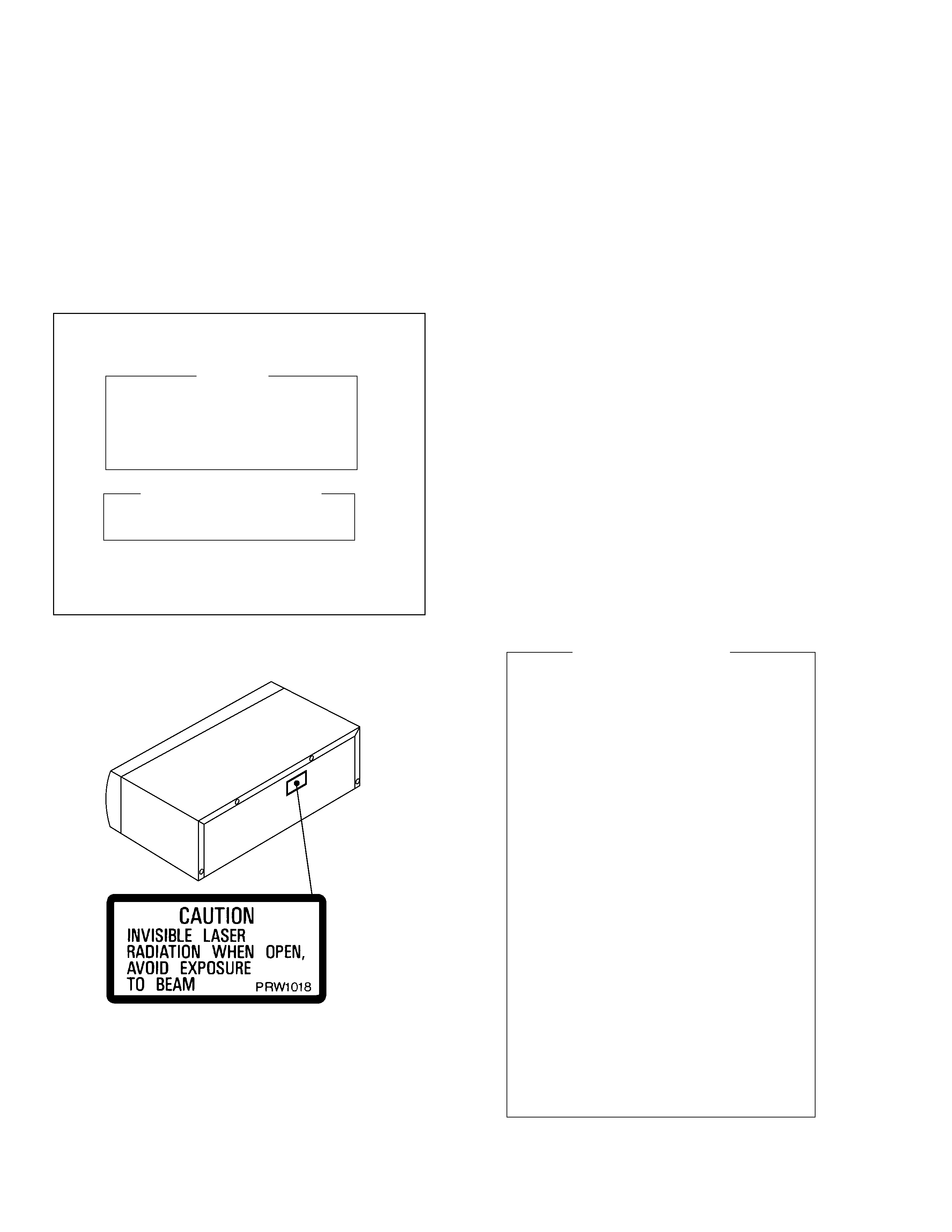
THIS PIONEER APPARATUS CONTAINS
LASER OF CLASS 1.
SERVICING OPERATION OF THE APPARATUS
SHOULD BE DONE BY A SPECIALLY
INSTRUCTED PERSON.
LASER DIODE CHARACTERISTICS
MAXIMUM OUTPUT POWER: 5 mw
WAVELENGTH: 780 785 nm
LABEL CHECK
1. SAFETY INFORMATION
This service manual is intended for qualified service technicians; it is not meant for the casual
do-it-yourselfer. Qualified technicians have the necessary test equipment and tools, and have been
trained to properly and safely repair complex products such as those covered by this manual.
Improperly performed repairs can adversely affect the safety and reliability of the product and may
void the warranty. If you are not qualified to perform the repair of this product properly and safely, you
should not risk trying to do so and refer the repair to a qualified service technician.
1. Laser Interlock Mechanism
The ON/OFF (ON: low level, OFF: high level)
status of S601 (LPS1) and S602 (LPS2)
switches for detecting the loading state is
detected by the system microprocessor, and
the design prevents laser diode oscillation
except when both switches S601 and S602
are ON (low level or clamped state).
Thus, interlock will no longer function if
switches S601 (LPS1) and S602 (LPS2) are
deliberatery shorted (low level). The interlock
also does not function in the test mode
.
Laser diode oscillation will continue, if pin 33
of CXA1782CQ (IC151) on the MOTHER
BOARD ASSY is connected to GND, or pin
50 of IC351 (LDON) is connected to low level
(ON), or else the terminals of Q151 are shorted
to each other (fault condition).
2. When the cover is opened with the servo
mechanism block removed to be turned over,
close viewing of the objective lens with the
naked eye will cause exposure to a Class 1
laser beam.
Additional Laser Caution
Refer to page 22.

PD-M427, PD-M407
3

PD-M427, PD-407
4
REAR
10
9
5
8
11
4
3
7
6
12
1
2
2. EXPLODED VIEWS AND PARTS LIST
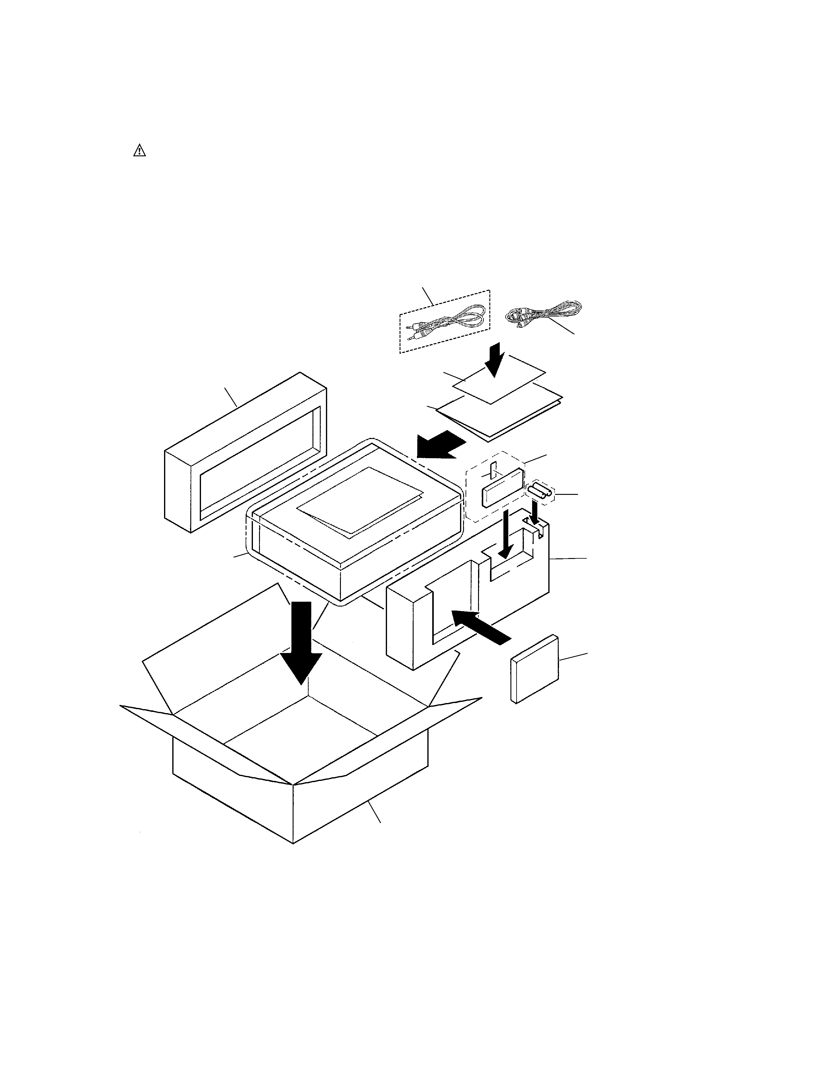
2.1 PACKING
NOTES :
÷ Parts marked by " NSP " are generally unavailable because they are not in our Master Spare Parts List.
÷ The
mark found on some component parts indicates the importance of the safety factor of the part.
Therefore, when replacing, be sure to use parts of identical designation.
÷ Screw adjacent to
mark on the product are used for disassembly.

PD-M427, PD-M407
5
1
Control Cable (for SR) (L=1 m)
Not used
PDE1247
PDE1247
PDE1247
3
Remote Control Unit (CU-PD104)
PWW1149
PWW1149
Not used
Not used
4
Battery Cover
PZN1010
PZN1010
Not used
Not used
6
Operating Instructions (English)
PRB1288
Not used
PRB1288
Not used
6
Operating Instructions
Not used
PRE1281
Not used
PRE1281
(English/Spanish/Chinese)
9
CD Packing Case
PHG2373
PHG2373
PHG2371
PHG2371
NSP
11
Dry Cell Battery (AAA/R03)
VEM-022
VEM-022
Not used
Not used
12
Caution 220V Label
Not used
ARR1003
Not used
ARR1003
1
Control Cable (for SR) (L=1 m)
See Contrast table (2)
2
Output Cable (L=1 m)
PDE1248
(for AUDIO)
3
Remote Control Unit
See Contrast table (2)
(CU-PD104)
4
Battery Cover
See Contrast table (2)
5
6-Compact Disc Magazine
PXA1617
6
Operating Instructions
See Contrast table (2)
7
Styrol Protector (F)
PHA1276
8
Styrol Protector (R)
PHA1277
9
CD Packing Case
See Contrast table (2)
10
Mirror Mat Sheet
Z23007
(750X600X0.5)
NSP
11
Dry Cell Battery (AAA/R03)
See Contrast table (2)
12
Caution 220V Label
See Contrast table (2)
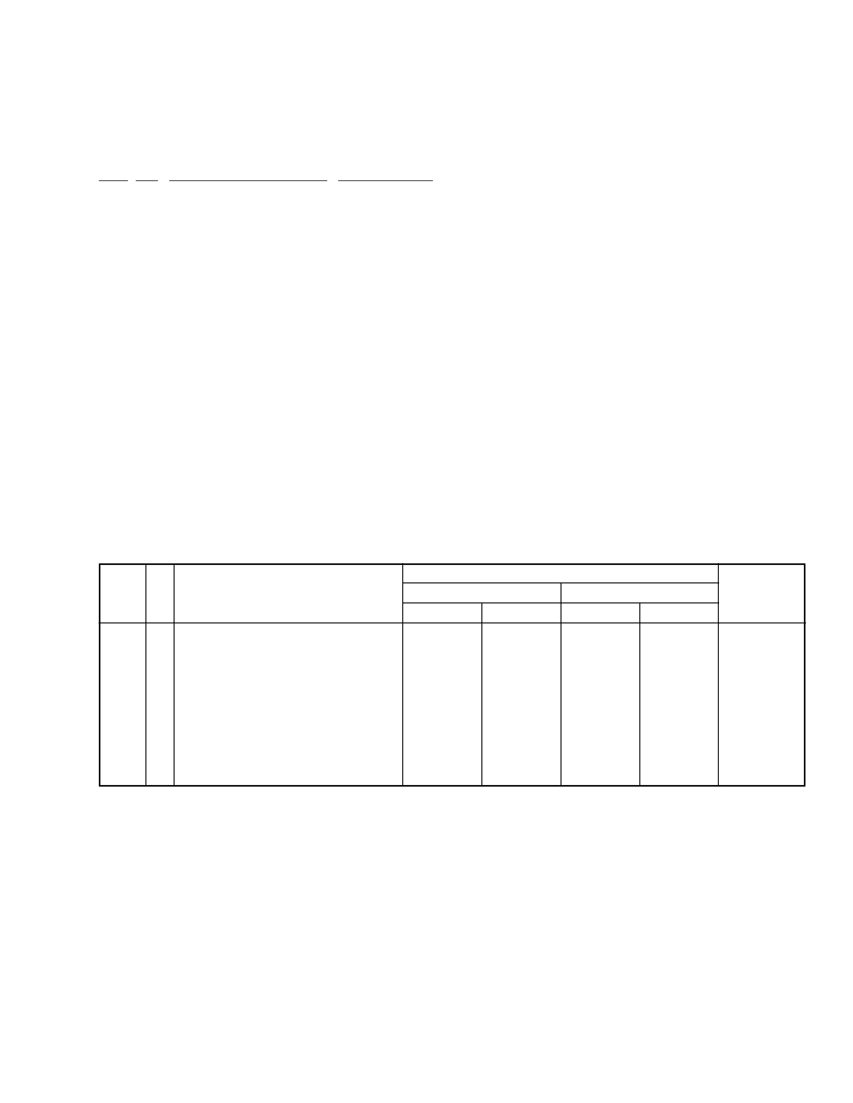
(1) PACKING PARTS LIST
Mark No.
Description
Parts No.
(2) CONTRAST TABLE
PD-M427/WPWXJ, RDXJ, PD-M407/WPWXJ and RDXJ are constructed the same except for the following:
WPWXJ
RDXJ
WPWXJ
RDXJ
Part No.
Mark
Remarks
Symbol and Description
No.
PD-M427
PD-M407
