PIONEER CORPORATION
4-1, Meguro 1-Chome, Meguro-ku, Tokyo 153-8654, Japan
PIONEER ELECTRONICS SERVICE INC.
P.O.Box 1760, Long Beach, CA 90801-1760 U.S.A.
PIONEER EUROPE N.V.
Haven 1087 Keetberglaan 1, 9120 Melsele, Belgium
PIONEER ELECTRONICS ASIACENTRE PTE.LTD. 253 Alexandra Road, #04-01, Singapore 159936
C PIONEER CORPORATION 2000
K-ZZS. APR. 2000 Printed in Japan
ORDER NO.
CRT2522
AMPLIFIER
GM-1006ZG
X1H/UC
Service
Manual
GM
CONTENTS
1. SAFETY INFORMATION............................................2
2. EXPLODED VIEWS AND PARTS LIST ......................2
3. SCHEMATIC DIAGRAM .............................................4
4. PCB CONNECTION DIAGRAM................................10
5. ELECTRICAL PARTS LIST........................................14
6. ADJUSTMENT .........................................................17
7. GENERAL INFORMATION.......................................18
7.1 DIAGNOSIS .......................................................18
7.1.1 DISASSEMBLY ..........................................18
7.1.2 CONNECTOR FUNCTION DESCRIPTION 19
8. SPECIFICATIONS .....................................................19
31
2
64
5
97
8
10
11
12
A
B
31
2
64
5
97
8
10
11
12
BA
C
D
E
FG
H
VEHICLE
DESTINATION
PRODUCED AFTER
PART No.
ID No.
PIONEER MODEL No.
PONTIAC AZTEK U.S.A. , CANADA
OCTOBER 2000
10422043
GM-1006ZG/X1H/UC

2
GM-1006ZG
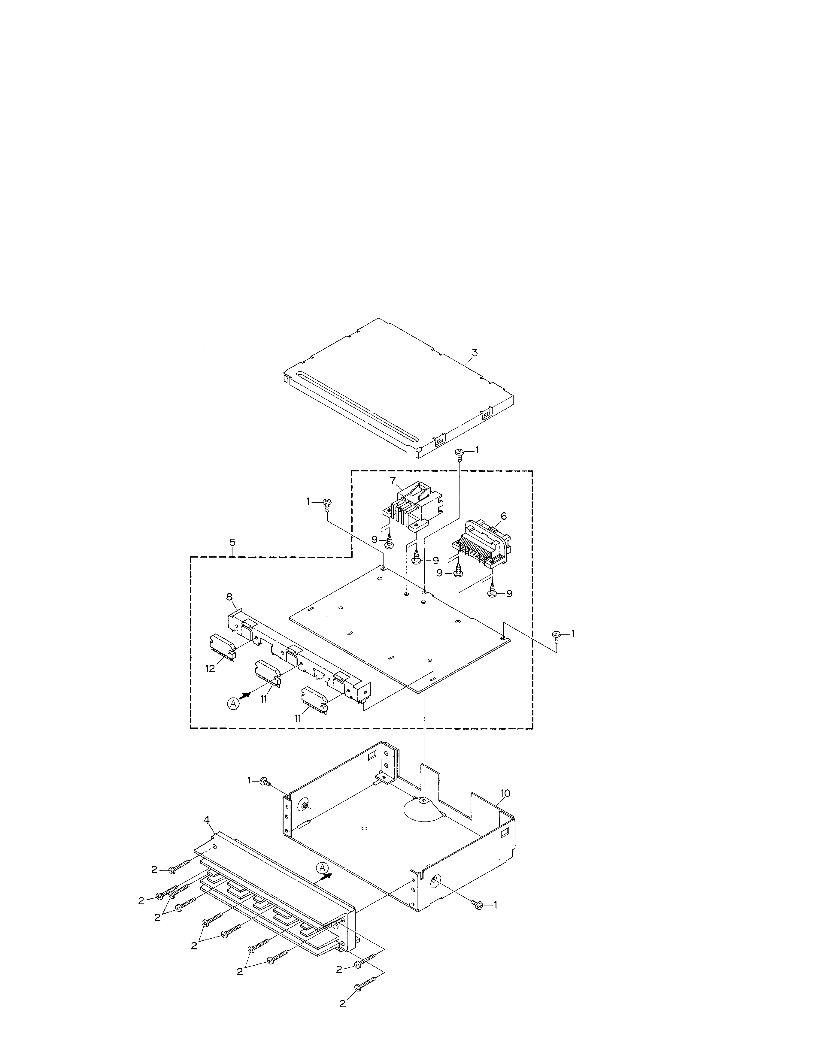
2. EXPLODED VIEWS AND PARTS LIST
2.1 EXTERIOR
1. SAFETY INFORMATION
This service manual is intended for qualified service technicians; it is not meant for the casual do-it-yourselfer.
Qualified technicians have the necessary test equipment and tools, and have been trained to properly and safely repair
complex products such as those covered by this manual.
Improperly performed repairs can adversely affect the safety and reliability of the product and may void the warranty.
If you are not qualified to perform the repair of this product properly and safely; you should not risk trying to do so
and refer the repair to a qualified service technician.

3
GM-1006ZG
NOTE:
- Parts marked by "*" are generally unavailable because they are not in our Master Spare Parts List.
- Screws adjacent to
mark on the product are used for disassembly.
- EXTERIOR SECTION PARTS LIST
Mark No. Description
Part No.
1 Screw
BMS30P050FMC
2 Screw
BMZ26P200FMC
3 Case
HNB0085
4 Heat Sink
HNR0107
5 Mother Unit
HWM6323
6 Connector(CN801)
HKE0028
7 Connector(CN802)
HKE0029
8 Holder
HNC0057
9 Screw
PPZ40P080SAD
10 Chassis Unit
HXA0281
11 IC(IC701,702)
TDA7384
12 IC(IC703)
PAL005A

A MOTHER UNIT
31
2
64
5
97
8
10
11
12
A
B
31
2
64
5
97
8
10
11
12
BA
C
D
E
FG
H
4
GM-1006ZG
A
1
234
B
C
D
12
34
A-a
A-b
A-a
A-a
A-b
A-b
A-b
A-b
A-a
A-a
Large size
SCH diagram
Guide page
Detailed page
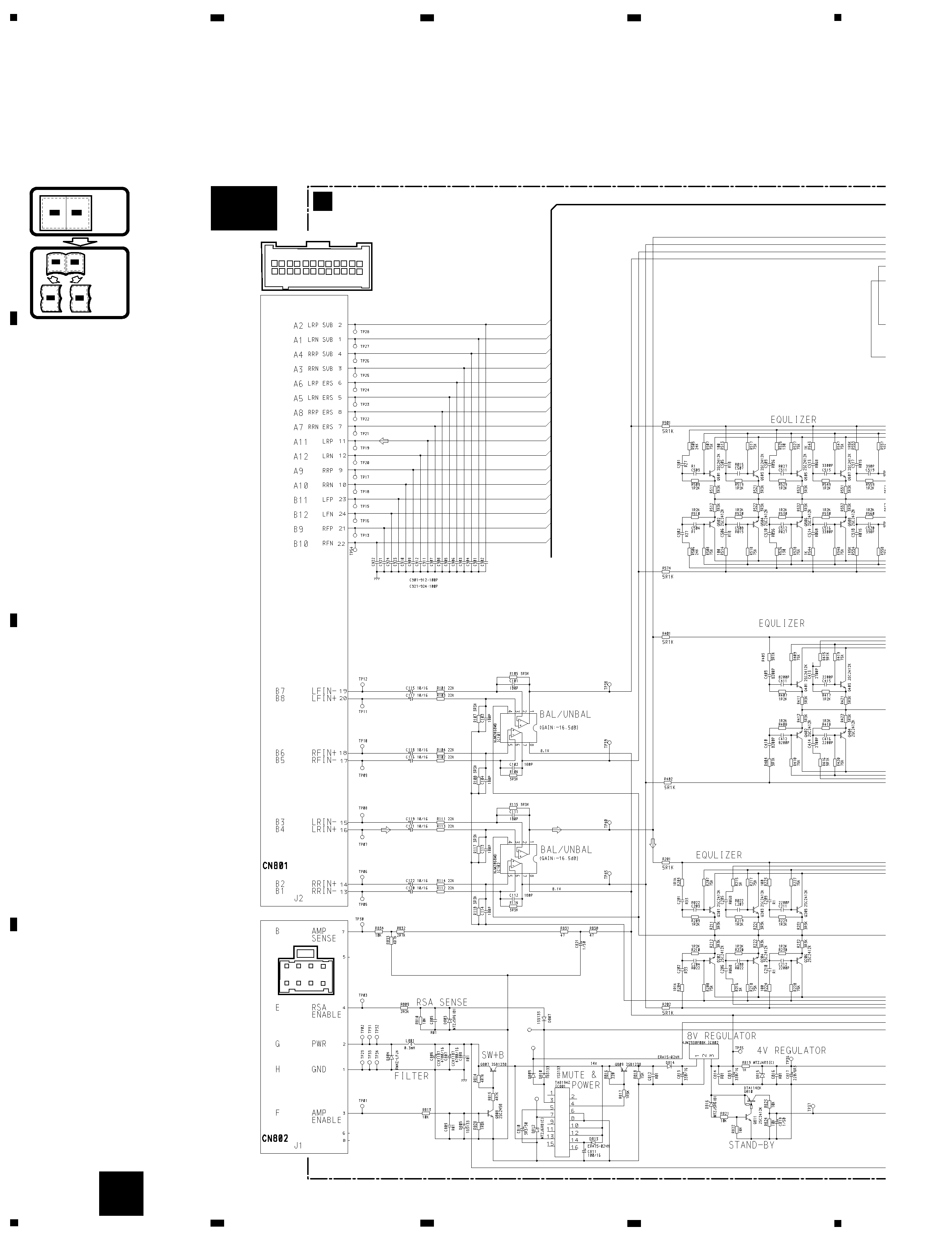
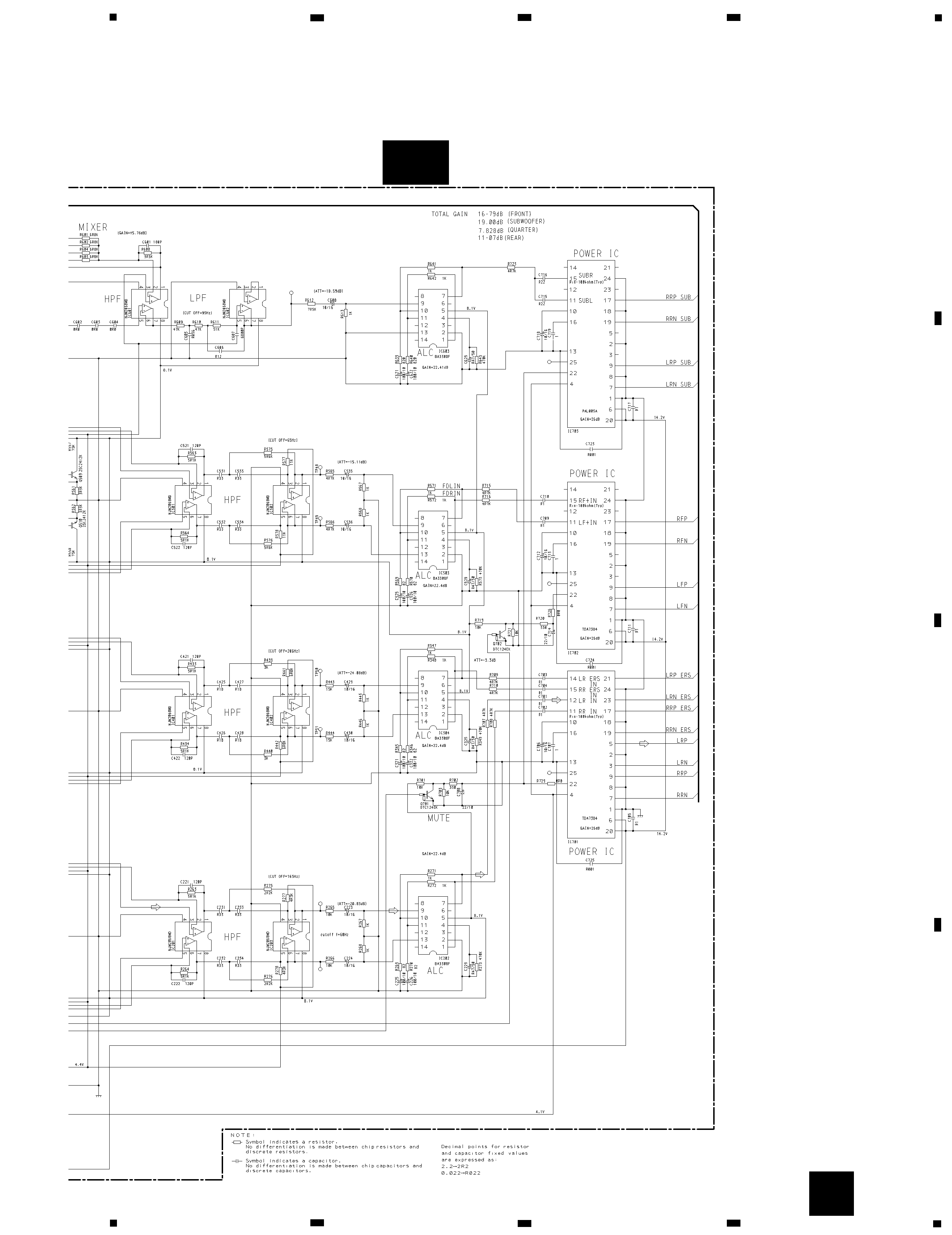
3. SCHEMATIC DIAGRAM
3.1 OVERALL CONNECTION DIAGRAM(GUIDE PAGE)
Note: When ordering service parts, be sure to refer to "EXPLODED VIEWS AND PARTS LIST" or "ELECTRICAL PARTS
LIST".
A-a
A

5
GM-1006ZG
5
6
7
8
A
B
C
D
5
6
7
8
A-b
A
