ORDER NO.
CRT2540
PUB. NO.
CRT2540
AUDIO SYSTEM
HEAD UNIT
Manufactured for TOYOTA
by PIONEER CORPORATION
LS430
Service
Manual
VEHICLE
DESTINATION
PRODUCED AFTER
ID No.
TOYOTA PART No.
PIONEER MODEL No.
LEXUS LS430
EUROPE
August 2000
P3903
86120-50690
FX-MG9106ZT/EW
FX-MG9106ZT-91/EW
LEXUS LS430
MIDDLE EAST
August 2000
P7802
86120-50700
FX-MG9106ZT/ES
FX-MG9106ZT-91/ES
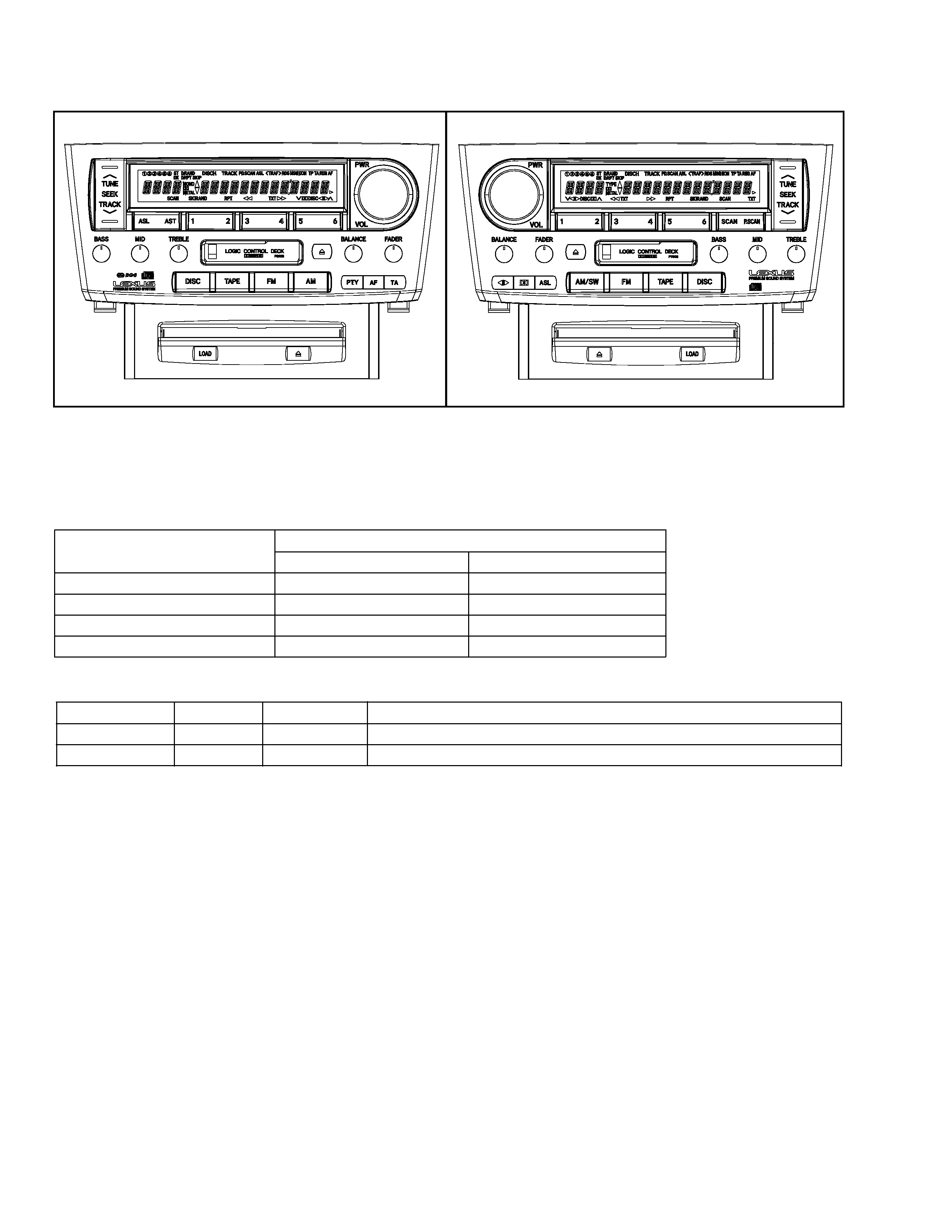
2
FX-MG9106ZT,MG9106ZT-91
- Dolby noise reduction manufactured under license from Dolby Laboratories Licensing Corporation.
"Dolby" and the double-D symbol are trademarks of Dolby Laboratories Licensing Corporation.
NOTE:
- FX-MG9106ZT-91/EW and FX-MG9106ZT-91/ES are supplementary genuine part for a TOYOTA vehicle,
and a Pioneer product for recycling stock.
- Supplementary model is identical to the original except for the addition of following items.
Part No.
Description
FX-MG9106ZT-91/EW
FX-MG9106ZT-91/ES
Polyethylene Bag
CEG1026
CEG1026
Carton
CHG4120
CHG4120
Contain Box
CHL4126
CHL4129
Protector
CHP2319,2320
CHP2319,2320
FX-MG9106ZT/EW
- This service manual should be used together with the following manual(s):
Model
Order No.
Mech. Module Remarks
CX-890
CRT2376
G1
CD Mechanism Module:Circuit Description, Mech.Description, Disassembly
CX-631
CRT1640
2L
Cassette Mech. Module:Mech.Description, Disassembly
FX-MG9106ZT/ES
ID No. P3903
ID No. P7802
- CD Player Service Precautions
1. For pickup unit(CXX1313) handling, please refer
to"Disassembly"(see page 83).
During replacement, handling precautions shall be
taken to prevent an electrostatic discharge(protection
by a short pin).
2. During disassembly, be sure to turn the power off
since an internal IC might be destroyed when a
connector is plugged or unplugged.
3. Please checking the grating after changing the
service pickup unit(see page 70).
3
FX-MG9106ZT,MG9106ZT-91
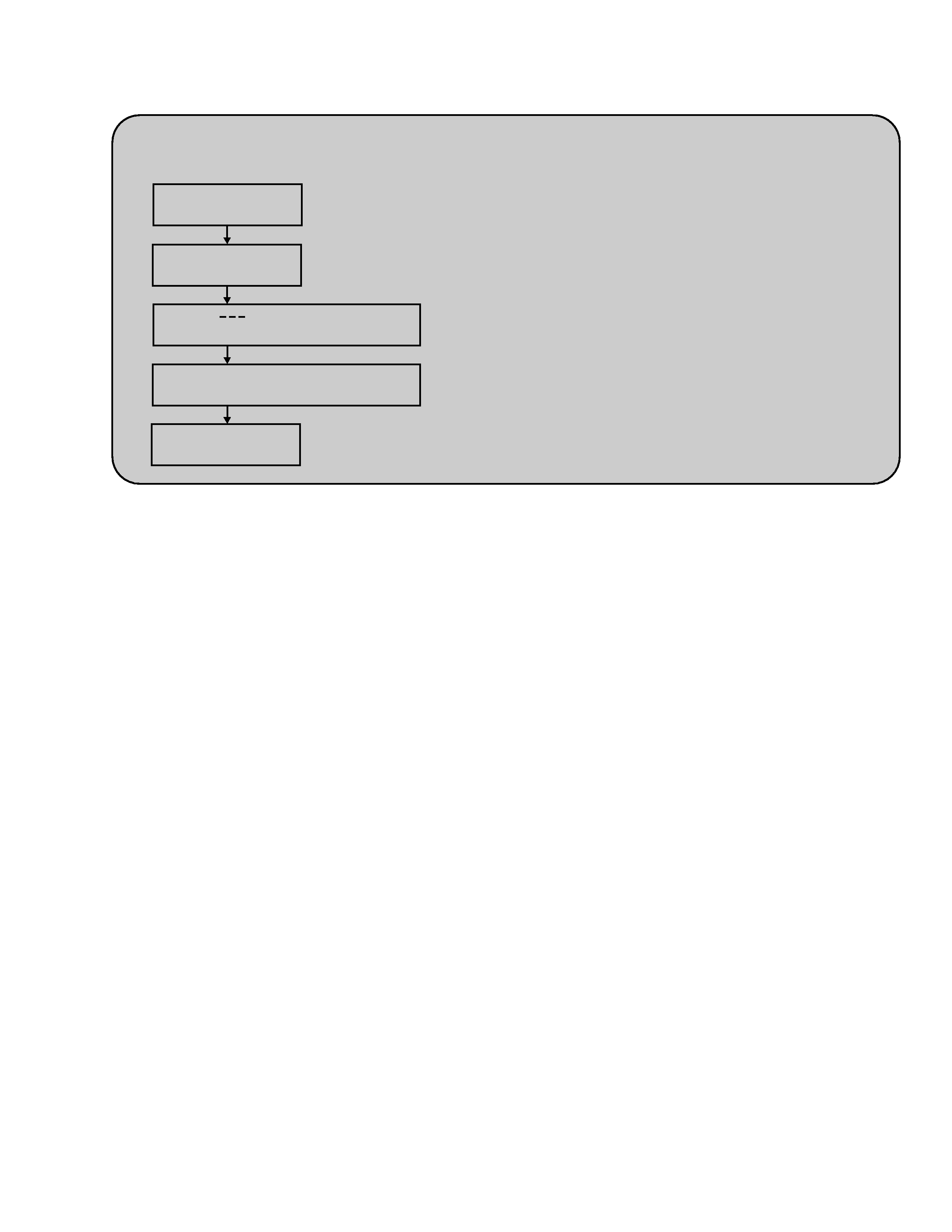
Bup On, Acc OFF
SEEK/TRACK UP+
DISC(CD)+Acc ON
Display :
Display : SHIP
Bup OFF, Acc OFF
Shift completion to the transportation mode.
Disc loading slot illumination : Lighting
Disc loading slot illumination : Blinking
The mode is shifting to the transportation mode.
- When the Repair is Complete
When the repair is complete, make the CD mechanism ready for transportation.
CONTENTS
1. SAFETY INFORMATION ............................................4
2. EXPLODED VIEWS AND PARTS LIST .......................5
3. BLOCK DIAGRAM AND SCHEMATIC DIAGRAM ...18
4. PCB CONNECTION DIAGRAM ................................38
5. ELECTRICAL PARTS LIST ........................................62
6. ADJUSTMENT..........................................................69
7. GENERAL INFORMATION .......................................72
7.1 DIAGNOSIS .......................................................72
7.1.1 TEST MODE.............................................72
7.1.2 SELF-DIAGNOSTIC FUNCTION..............77
7.1.3 DISASSEMBLY ........................................83
7.1.4 PCB LOCATIONS .....................................88
7.1.5 CONNECTOR FUNCTION DESCRIPTION ..89
7.2 PARTS ................................................................90
7.2.1 IC ..............................................................90
7.2.2 DISPLAY...................................................95
7.3 SYSTEM BLOCK DIAGRAM .............................97
7.4 OPERATIONAL FLOW CHART..........................98
8. OPERATIONS AND SPECIFICATIONS.....................99
4
FX-MG9106ZT,MG9106ZT-91
1. SAFETY INFORMATION
This service manual is intended for qualified service technicians; it is not meant for the casual do-it-yourselfer.
Qualified technicians have the necessary test equipment and tools, and have been trained to properly and safely repair
complex products such as those covered by this manual.
Improperly performed repairs can adversely affect the safety and reliability of the product and may void the warranty.
If you are not qualified to perform the repair of this product properly and safely; you should not risk trying to do so
and refer the repair to a qualified service technician.
1. Safety Precautions for those who Service this Unit.
· When checking or adjusting the emitting power of the laser diode exercise caution in order to get safe, reliable
results.
Caution:
1. During repair or tests, minimum distance of 13cm from the focus lens must be kept.
2. During repair or tests, do not view laser beam for 10 seconds or longer.
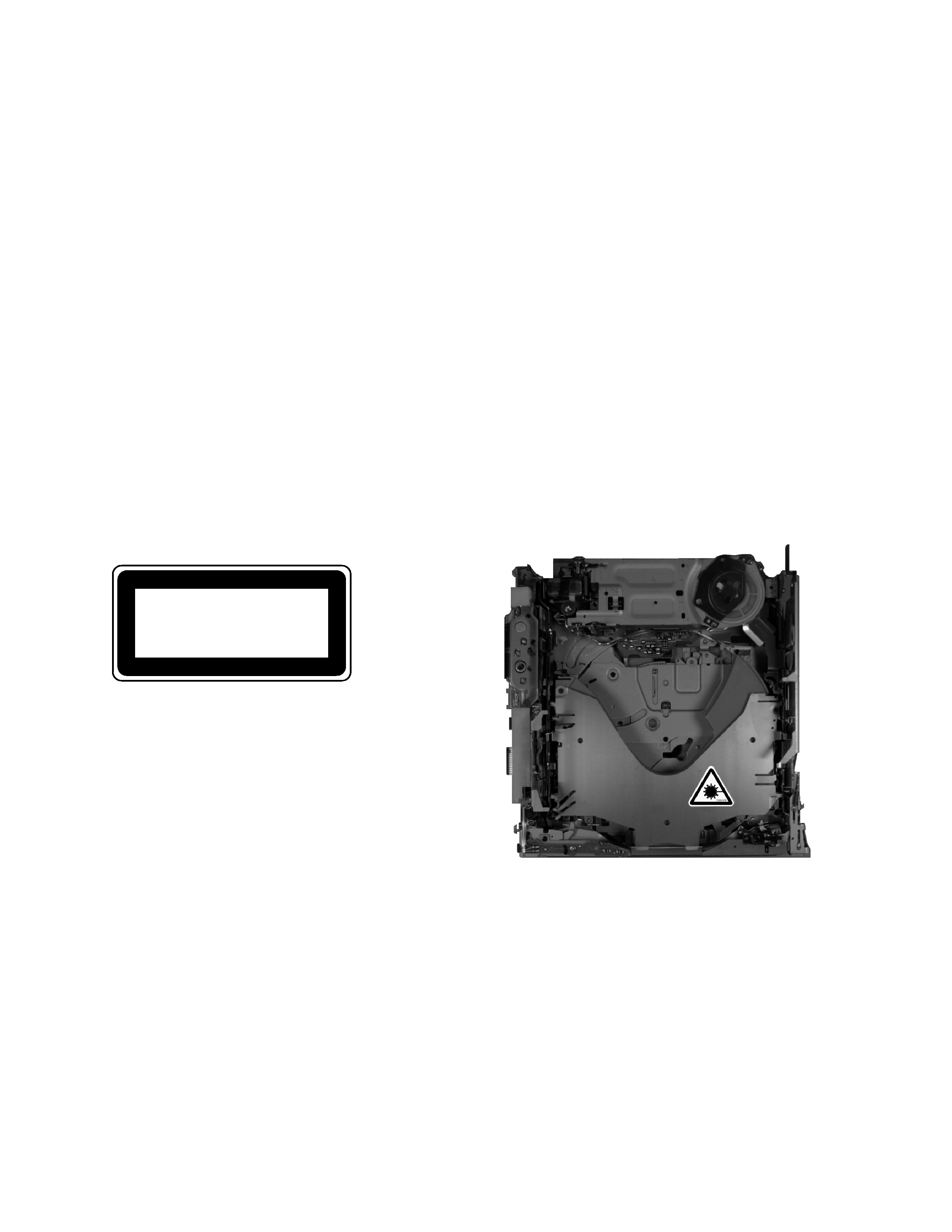
2. A "CLASS 1 LASER PRODUCT" label is affixed to the
bottom of the player.
3. The triangular label is attached to the mechanism
unit holder.
4. Specifications of Laser Diode
Specifications of laser radiation fields to which human access is possible during service.
Wavelength
=
800 nanometers
CLASS 1
LASER PRODUCT
5
FX-MG9106ZT,MG9106ZT-91
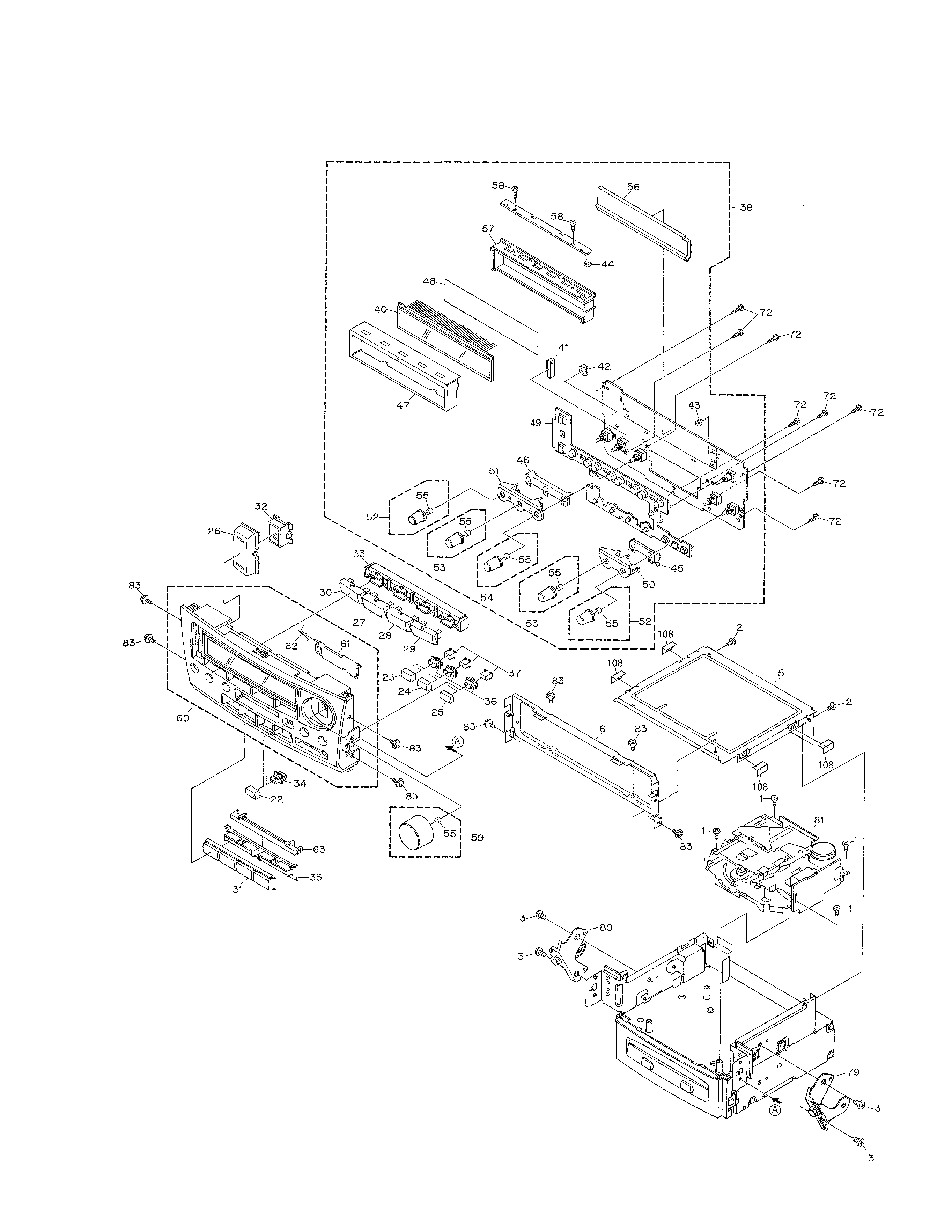
2.2 EXTERIOR (FX-MG9106ZT/EW)
