ORDER NO.
PIONEER ELECTRONIC CORPORATION 4-1, Meguro 1-Chome, Meguro-ku, Tokyo 153-8654, Japan
PIONEER ELECTRONICS SERVICE, INC. P.O. Box 1760, Long Beach, CA 90801-1760, U.S.A.
PIONEER ELECTRONIC (EUROPE) N.V. Haven 1087, Keetberglaan 1, 9120 Melsele, Belgium
PIONEER ELECTRONICS ASIACENTRE PTE. LTD. 501 Orchard Road, #10-00 Lane Crawford Place, Singapore 0923
PIONEER ELECTRONIC CORPORATION 1998
DVL-K88
RRV1902
DVD LD PLAYER
1. SAFETY INFORMATION ...................................... 2
2. EXPLODED VIEWS AND PARTS LIST ................ 3
3. SCHEMATIC DIAGRAM ..................................... 16
4. PCB CONNECTION DIAGRAM .......................... 40
5. PCB PARTS LIST ............................................... 56
6. ADJUSTMENT .................................................... 63
CONTENTS
7. GENERAL INFORMATION ................................ 78
7.1 IC .................................................................. 78
7.2 DISASSEMBLY/ASSEMBLY ........................ 80
7.3 BLOCK DIAGRAM ....................................... 82
8. PANEL FACILITIES AND SPECIFICATIONS .... 84
THIS MANUAL IS APPLICABLE TO THE FOLLOWING MODEL(S) AND TYPE(S).
T ZZM JAN. 1998 Printed in Japan
¶Refer to the service guide RRV1896 for DV-505.
IC information is described in the service guide.
e
p
y
T
l
e
d
o
M
t
n
e
m
e
r
i
u
q
e
R
r
e
w
o
P
e
h
t
y
b
d
e
t
r
e
v
n
o
c
e
b
n
a
c
e
g
a
t
l
o
v
e
h
T
.
d
o
h
t
e
m
g
n
i
w
o
l
l
o
f
l
a
n
o
i
g
e
R
s
e
d
o
c
n
o
i
t
c
i
r
t
s
e
r
)
r
e
b
m
u
n
n
o
i
g
e
r
(
8
8
K
-
L
V
D
L
RO
V
0
4
2
0
2
2
/
V
7
2
1
0
1
1
C
At
c
e
l
e
s
c
i
t
a
m
o
t
u
A3
DVL-K88

2
DVL-K88
1. SAFETY INFORMATION
This service manual is intended for qualified service technicians; it is not meant for the casual
do-it-yourselfer. Qualified technicians have the necessary test equipment and tools, and have been
trained to properly and safely repair complex products such as those covered by this manual.
Improperly performed repairs can adversely affect the safety and reliability of the product and may
void the warranty. If you are not qualified to perform the repair of this product properly and safely, you
should not risk trying to do so and refer the repair to a qualified service technician.
IMPORTANT
THIS PIONNER APPARATUS CONTAINS
LASER OF CLASS 1.
SERVICING OPERATION OF THE APPARATUS
SHOULD BE DONE BY A SPECIALLY
INSTRUCTED PERSON.
LASER DIODE CHARACTERISTICS
·FOR DVD
MAXIMUM OUTPUT POWER : 7 mw
WAVELENGTH : 650 nm
·FOR CD/LD
MAXIMUM OUTPUT POWER : 5 mw
WAVELENGTH : 780-785 nm
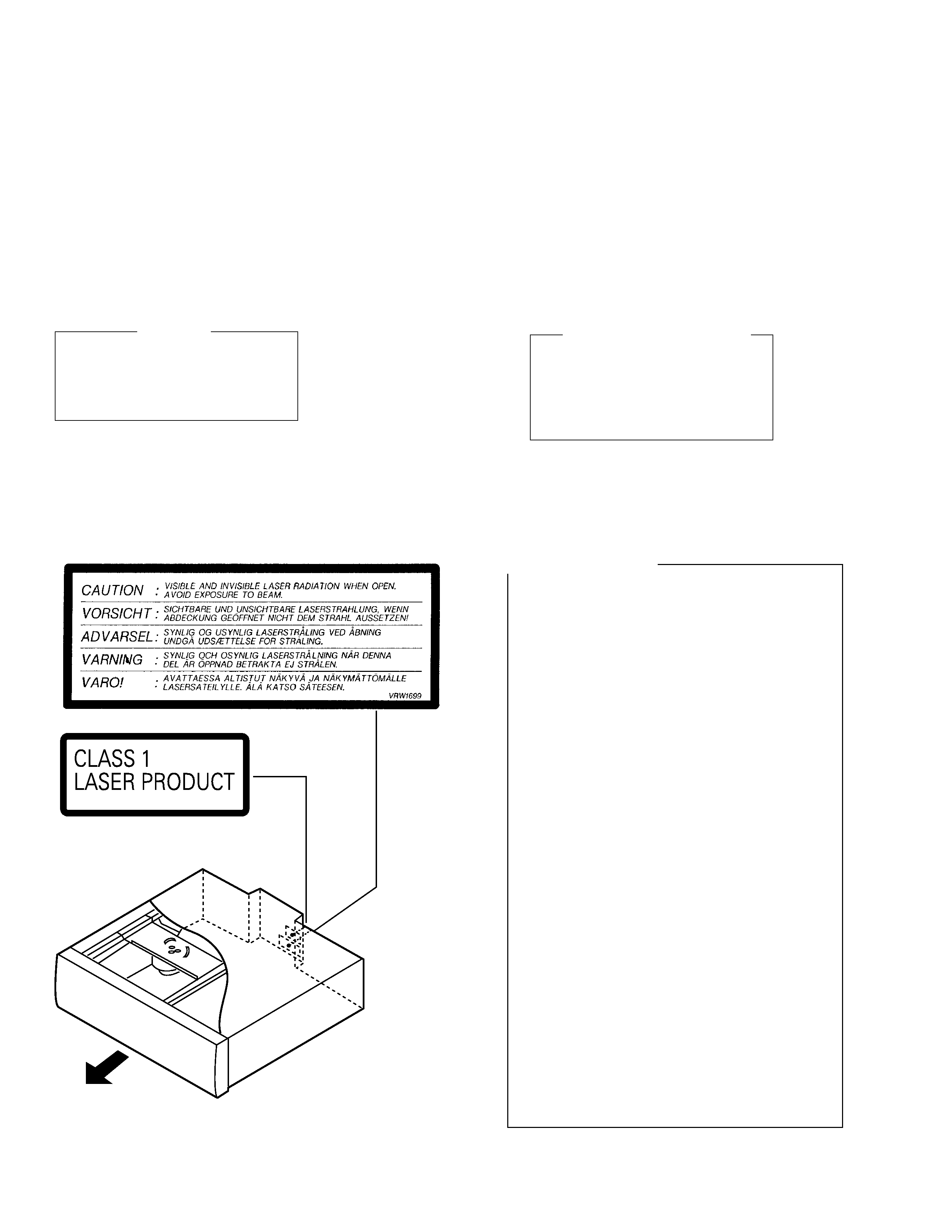
LABEL CHECK
FRONT
FRONT
(Printed on the Rear Cover)
Additional Laser Caution
1. The ON/OFF statuses of the side-A/B detection switch
(Lever switch connecting to the TNMB assy), slider-position
detection switches (INNER and OUTER on the PKSB assy),
loading-status detection switches (SW1, 2 and 3 on the LMSB
assy), side B inside detection switch (S901 on the BISB assy)
and CLD pickup active detection switch (S903 on the LCSB
assy) are detected by the microprocessor (IC101 in the CLD
MAIN assy). Also the DVD pickup active detection switch (S902
on the DCSB assy) is detected by the microprocessor (IC501
in the DVD MAIN assy).
· To permit the laser diode of CLD pickup to oscillate, it is
required to set the CLD pickup active detection switch (S903 :
OFF) and the slider-position detection switches for the LD
ACTIVE status (INNER : OFF, OUTER: OFF), and to set the
loading-status detection switches for tilt neutral state (SW1 :
ON, SW2 : OFF, SW3 : ON). As long as these requirements
are not satisfied, the laser diode will not oscillate. When the
requirements are met in any way, the laser diode can oscillate.
The laser diode oscillation will continue if pin 13 of IC801 is
shorted to GND or the emitter and collector of Q834 are shorted
each other (fault condition) in the CLD MAIN assy.
· To permit the laser diode of DVD pickup to oscillate, it is
required to set the DVD pickup active detection switch (S902
:OFF) and each switch and a state of laser diode are contents
same as state of CLD pickup mentioned above. The laser
diode oscillation will continue if pin 13 of IC101 is shorted to
+5V (fault condition) in the DVD MAIN assy.
In the test mode
, the laser diode oscillates when the micro-
processor detects a PLAY signal, or when the PLAY key is
pressed (S107 ON in the FLKB assy), with the above require-
ments satisfied.
2. When the cover is open, close viewing through the objective
lens with the naked eye will cause exposure to a Class 1
laser beam.
: Refer to page 66.

DVL-K88
3
2. EXPLODED VIEWS AND PARTS LIST
Parts marked by "NSP" are generally unavailable because they are not in our Master Spare Parts List.
The
mark found on some component parts indicates the importance of the safety factor of the part.
Therefore, when replacing, be sure to use parts of identical designation.
Screws adjacent to
mark on product are used for disassembly.
NOTES:
2.1 PACKING
Mark No.
Description
Part No.
NSP
1
DRY CELL BATTERY(AA/R6P) VEM-013
2
VIDEO CORD(L=1.5m)
VDE1048
3
AUDIO CORD(L=1.5m)
VDE1033
4
AC POWER CORD
ADG1127
5
POLYETHYLENE BAG
Z21-038
6
REMOTE CONTROL UNIT
VXX2537
(CU-DV016)
7
BATTERRY COVER
VNK3703
NSP
8
CAUTION
VRM1071
9
OPERATING INSTRUCTIONS
VRB1191
(ENGLISH)
10
OPERATING INSTRUCTIONS
VRD1079
(TRAD-CHINESE)
11
·····
12
MIRROR MAT SHEET
VHL1018
13
PAD F
VHA1206
14
PAD R
VHA1207
15
PACKING CASE
VHG1728
PARTS LIST
1
2
3
4
5
6
8
9
13
14
15
5
7
12
10

DVL-K88
4
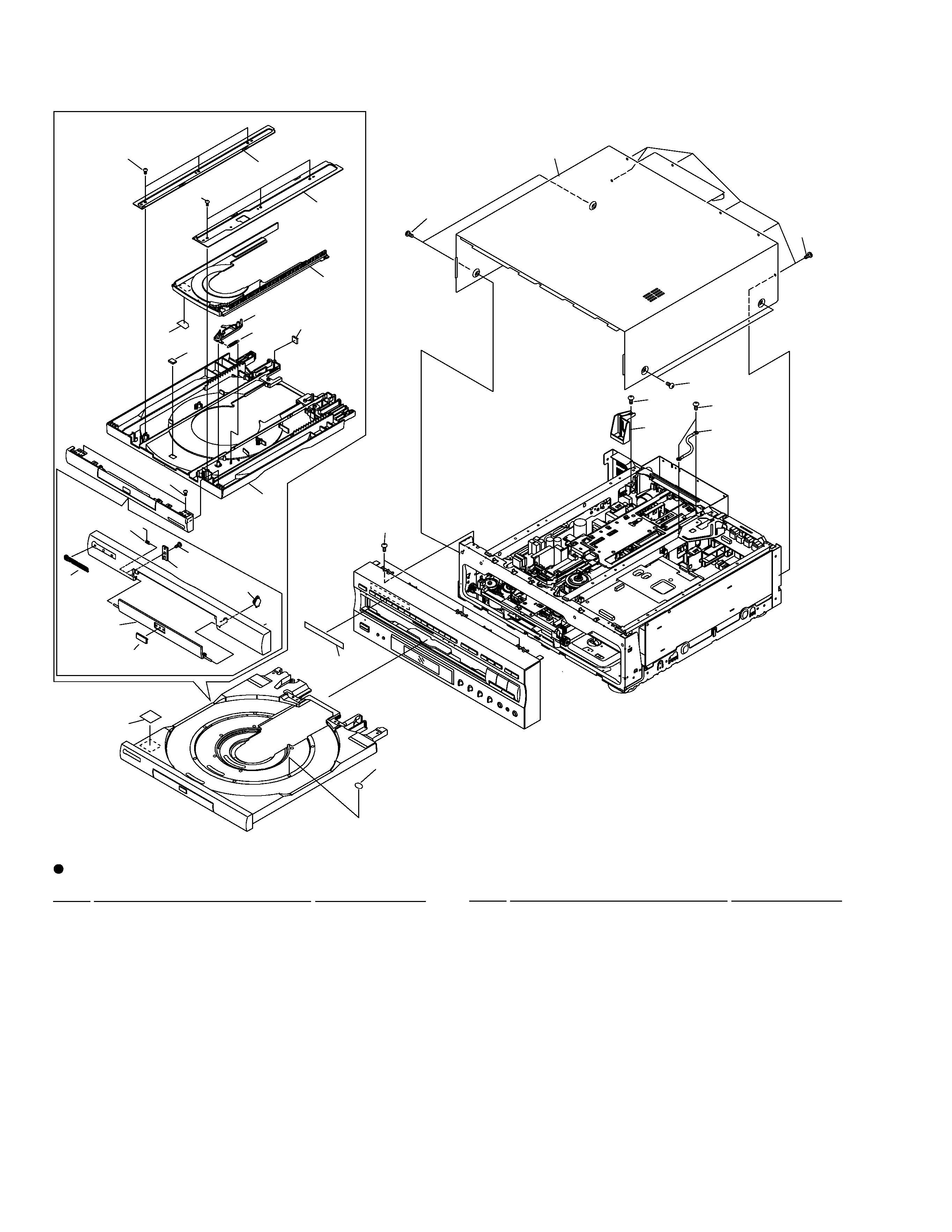
2.2 EXTERIOR SECTION
Mark No.
Description
Part No.
1
LD TRAY ASSY
VXA2173
2
CUSHION
VEC1682
NSP
3
LABEL
VRW1289
4
DAMP CUSHION
VEC1683
5
CD TRAY
VNK3922
6
LABEL
VRW1628
7
GUIDE PLATE (R)
VNE1939
8
GUIDE PLATE (L)
VNE1938
9
LOCK PLATE
VNL1703
10
LOCK PLATE SPRING
VBH1188
PARTS LIST
11
TRAY PANEL
VNK4187
12
DVD DOOR ASSY
VXA2355
13
DOOR SPRING
VBH1248
14
DOOR HOLDER
VNL1697
15
DAMPER
VXA1999
16
DVD PLATE
VAM1075
17
BONNET CASE S
VXX2561
18
NAME PLATE
VAM1073
19
SCREW
BBZ30P080FMC
20
SCREW
BCZ40P060FZK
21
SHIPPING CAM
VNL1729
NSP
22
CORD WITH PLUG
DE007VF0
23
SCREW
IBZ30P080FMC
NSP
24
GETTER
VRW1720
Mark No.
Description
Part No.
2x12
3
4
6
4
1
14
19
13
19
15
12
11
16
18
10
9
19
19
5
8
7
19
20
20
17
19
22
19
21
23
24

DVL-K88
5
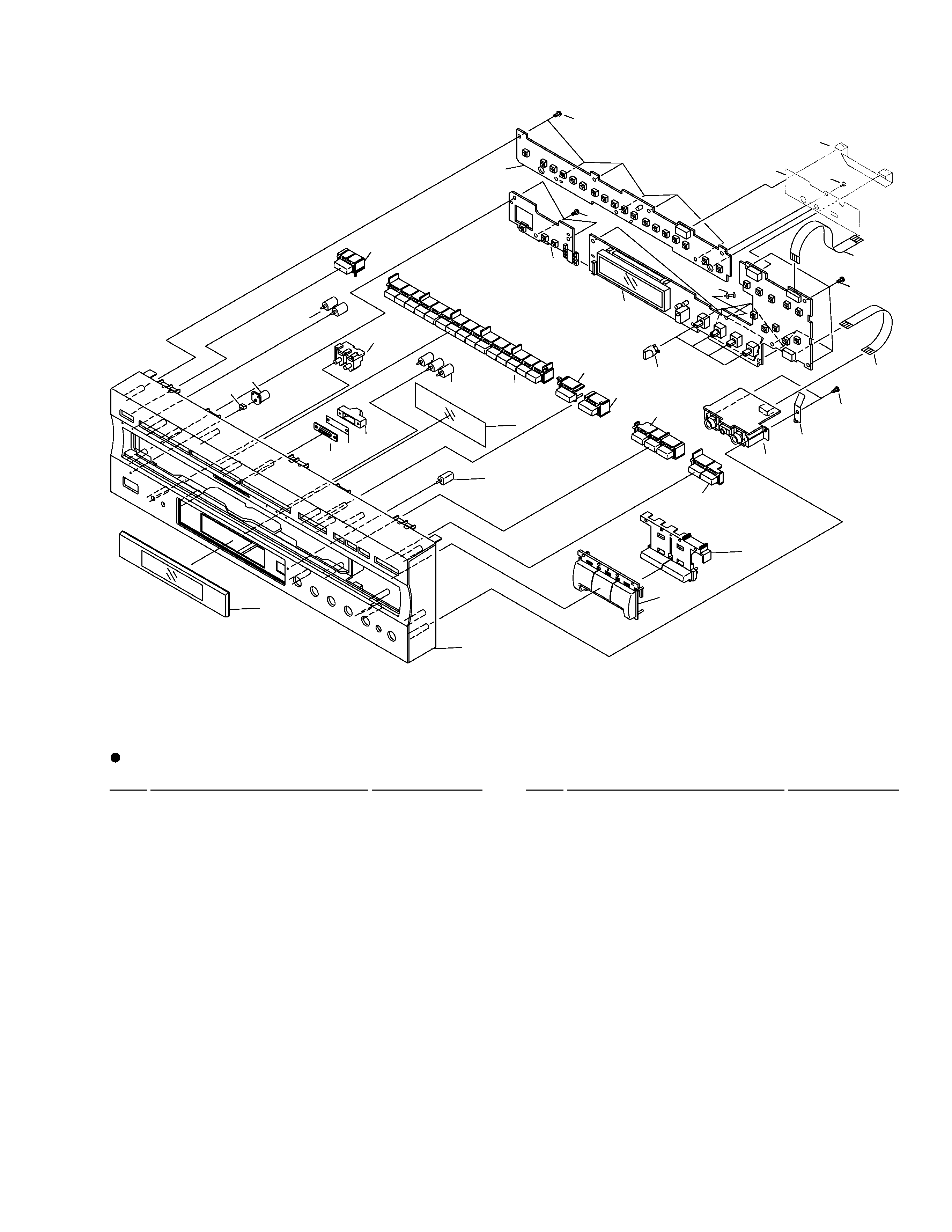
2.3 FRONT PANEL SECTION
Mark No.
Description
Part No.
1
FRONT PANEL
VNK4196
2
FL FILTER
VEC1722
3
FL LENS
VEC1954
4
LED LENS 1
RNK2066
5
LENS HOLDER
VNK4151
6
·····
7
L KEY C
VNK3070
8
MAIN KEY
VNK4199
9
CTL KEY
VNK4193
10
17 KEY
VNK4189
11
DVD KEY
VNK4198
12
VCD KEY
VNK4197
13
LED LENS
VNK4195
14
KYLB ASSY
VWG1946
15
ILLUMINATION LENS
VNK4194
PARTS LIST
Mark No.
Description
Part No.
16
ILLUMINATION FILTER
VEC1950
17
ILLUMI HOLDER
VNK4289
18
FLKY ASSY
VWG1945
19
VOLUME KNOB
VNK1733
NSP
20
PWSB ASSY
VWG1947
21
FLEXIBLE CABLE(14P)
VDA1657
22
FLEXIBLE CABLE(10P)
VDA1655
23
FLEXIBLE CABLE(7P)
VDA1656
24
SCREW
BBZ30P080FMC
25
SHEET F
VEC1972
26
MICB ASSY
VWV1602
27
EARTH PLATE
VBK1070
NSP
28
PCB SPACER
AEC1371
1
3
8(1/2)
9
13(2/2)
2
15
16
17
13
10(1/2)
4
5
7
13(1/2)
8(2/2)
12(1/2)
12(2/2)
11
10(2/2)
26
27
24
19
23
18
20
24
24
24
21
24
25
22
28
14
