PIONEER CORPORATION
4-1, Meguro 1-Chome, Meguro-ku, Tokyo 153-8654, Japan
PIONEER ELECTRONICS SERVICE INC.
P.O.Box 1760, Long Beach, CA 90801-1760 U.S.A.
PIONEER ELECTRONIC [EUROPE] N.V.
Haven 1087 Keetberglaan 1, 9120 Melsele, Belgium
PIONEER ELECTRONICS ASIACENTRE PTE.LTD. 253 Alexandra Road, #04-01, Singapore 159936
C PIONEER CORPORATION 1999
K-ZZB. SEPT. 1999 Printed in Japan
ORDER NO.
CRT2355
HIGH POWER CD PLAYER WITH RDS TUNER
DEH-2096ZRN
X1B/EW
Service
Manual
RENAULT
CONTENTS
1. SAFETY INFORMATION ............................................2
2. EXPLODED VIEWS AND PARTS LIST .......................3
3. BLOCK DIAGRAM AND SCHEMATIC DIAGRAM .....8
4. PCB CONNECTION DIAGRAM ................................24
5. ELECTRICAL PARTS LIST ........................................34
6. ADJUSTMENT..........................................................40
7. GENERAL INFORMATION .......................................46
7.1 DIAGNOSIS ........................................................46
7.1.1 TEST MODE ..............................................46
7.1.2 DISASSEMBLY .........................................50
7.1.3 CONNECTOR FUNCTION DESCRIPTION .......54
7.2 IC ........................................................................55
7.3 SYSTEM BLOCK DIAGRAM ..............................60
8. OPERATIONS AND SPECIFICATIONS.....................61
VEHICLE
DESTINATION
PRODUCED AFTER
PART No.
ID No.
PIONEER MODEL No.
ESPACE
EUROPE
September 1999
6025 31 5404
DEH-2096ZRN/X1B/EW
- This service manual should be used together with the following manual(s):
Model
Order No.
Mech. Module
Remarks
CX-916
CRT2300
S8
CD Mechanism Module:Circuit Description, Mechanism Description, Disassembly

2
DEH-2096ZRN
- CD Player Service Precautions
1. For pickup unit(CXX1285) handling, please refer
to"Disassembly"(see page 48).
During replacement, handling precautions shall be
taken to prevent an electrostatic discharge(protection
by a short pin).
2. During disassembly, be sure to turn the power off
since an internal IC might be destroyed when a con-
nector is plugged or unplugged.
3. Please checking the grating after changing the ser-
vice pickup unit(see page 42).
1. SAFETY INFORMATION
This service manual is intended for qualified service technicians; it is not meant for the casual do-it-yourselfer.
Qualified technicians have the necessary test equipment and tools, and have been trained to properly and safely repair
complex products such as those covered by this manual.
Improperly performed repairs can adversely affect the safety and reliability of the product and may void the warranty.
If you are not qualified to perform the repair of this product properly and safely; you should not risk trying to do so
and refer the repair to a qualified service technician.
1. Safety Precautions for those who Service this Unit.
· When checking or adjusting the emitting power of the laser diode exercise caution in order to get safe, reliable
results.
Caution:
1. During repair or tests, minimum distance of 13cm from the focus lens must be kept.
2. During repair or tests, do not view laser beam for 10 seconds or longer.
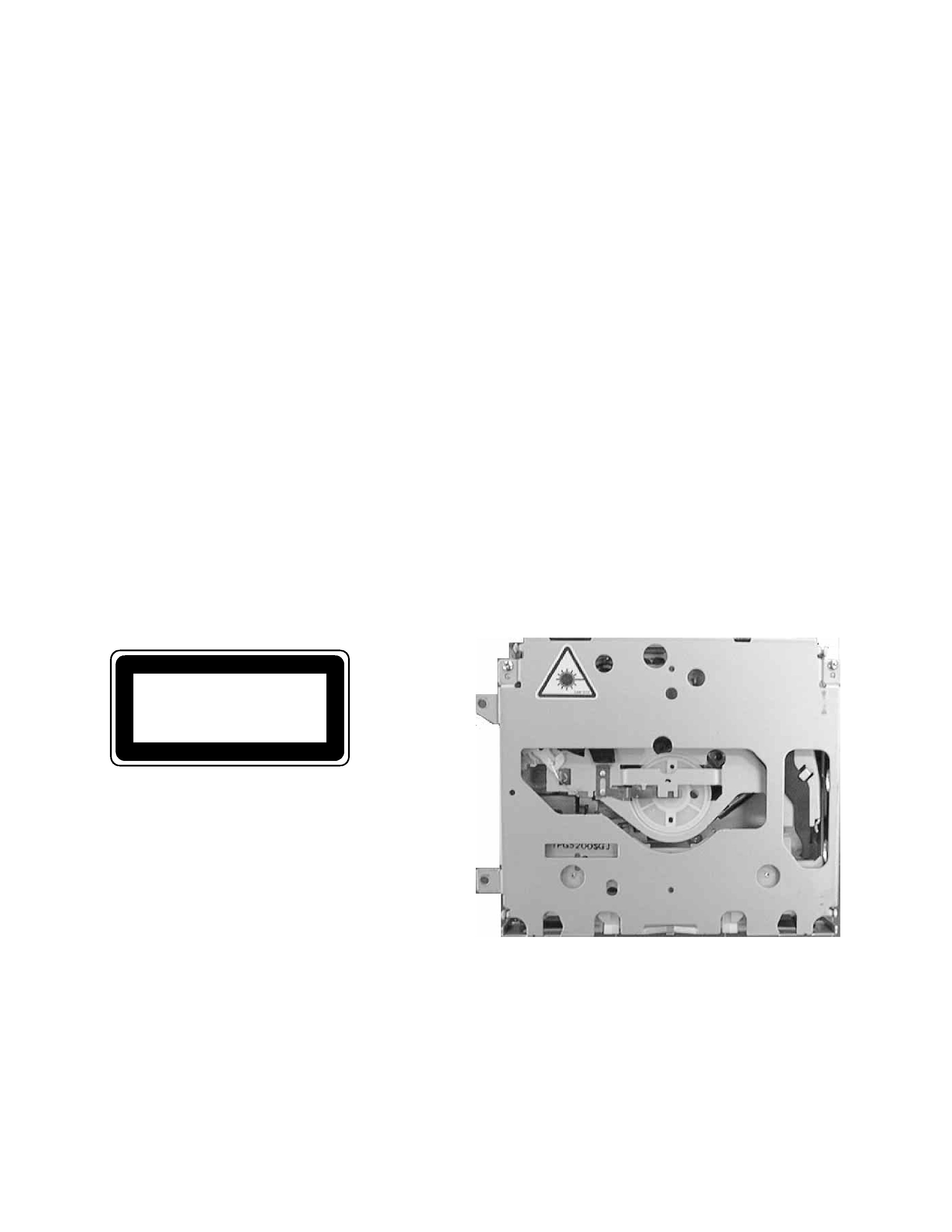
2. A "CLASS 1 LASER PRODUCT" label is affixed to the
bottom of the player.
3. The triangular label is attached to the mechanism
unit frame.
4. Specifications of Laser Diode
Specifications of laser radiation fields to which human access is possible during service.
Wavelength
=
800 nanometers
CLASS 1
LASER PRODUCT

DEH-2096ZRN
2. EXPLODED VIEWS AND PARTS LIST
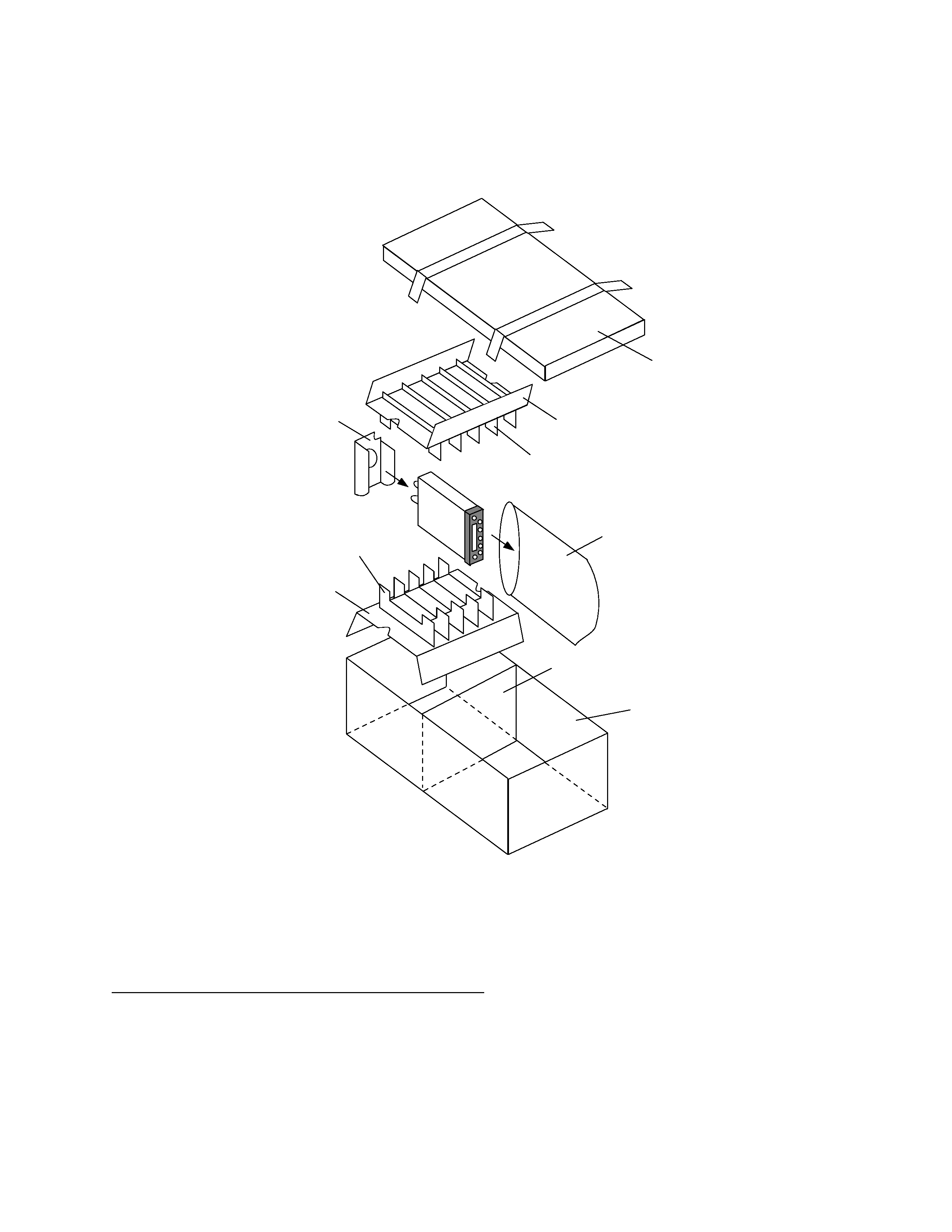
2.1 PACKING
6
1
7
2
5
4
3
3
4
3
1 Polyethylene Bag
UEG1227
2 Contain Box
UHL3836
3 Protector
UHP1900
4 Protector
UHP1901
5 Protector
UHP1902
6 Lid
UHW1584
7 Separator
UHW1608
Mark No. Description
Part No.
- PACKING SECTION PARTS LIST
NOTE:
- Parts marked by "*" are generally unavailable because they are not in our Master Spare Parts List.
- Screws adjacent to
mark on the product are used for disassembly.

4
DEH-2096ZRN
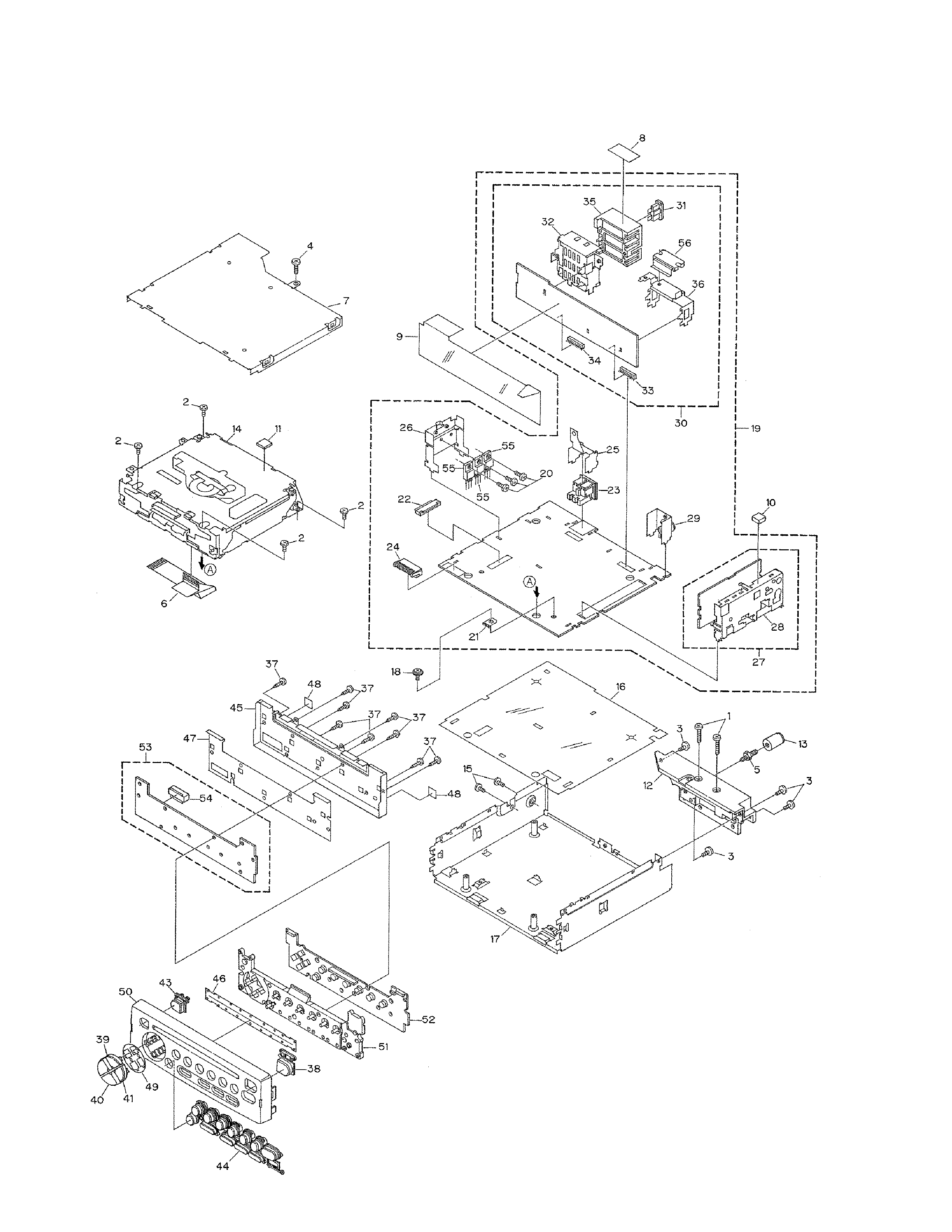
2.2 EXTERIOR

DEH-2096ZRN
1 Screw
BMZ26P200FMC
2 Screw
BSZ26P060FMC
3 Screw
BSZ30P080FMC
4 Screw
BMZ26P160FMC
5 Screw
CBA1002
6 Connector
CDE5965
7 Case
CNB2567
8 Spacer
CNM5270
9 Insulator
CNM6229
10 Conductor
CNM6449
11 Conductor
CNM6450
12 Heat Sink
CNR1543
13 Bush
CNV3253
14 CD Mechanism Module(S8) CXK5253
15 Screw
BSZ30P080FMC
16 Insulator
CNM6228
17 Chassis Unit
CXB5503
18 Screw
ISS26P055FUC
19 Mother Unit
UWM6487
20 Screw
BMZ30P060FMC
21 Terminal(CN402)
CKF1059
22 Connector(CN951)
CKS1960
23 DIN Socket(CN651)
CKS3189
24 Plug(CN902)
CKS3537
25 Holder
CNC6702
26 Holder
CNC8303
27 FM/AM Tuner Unit
CWE1416
28 Holder
CNC6555
29 Holder Unit
CXB3782
30 Amp Unit
UWM6722
31 Fuse(10A)
CEK1136
32 Connector(CN301)
CKM1258
33 Plug(CN302)
CKS1607
34 Plug(CN303)
CKS1607
35 Holder
CNC5144
36 Holder
CNC8743
37 Screw
BPZ20P080FMC
38 Button(POWER)
CAC4822
39 Button(+)
CAC6067
40 Button(-)
CAC6068
41 Button(>)
CAC6069
42 Button(<)
CAC6070
43 Button(
)
CAC6071
44 Button
CAC6157
45 Shield
CNC8305
46 Cover
CNM4768
47 Insulator
CNM6231
48 Insulator
CNM6582
49 Spacer
CNM6649
50 Grille
CNS5467
51 Lighting Conductor
CNV5769
52 Rubber
CNV5770
53 Keyboard Unit
UWM6488
54 Socket(CN904)
CKS3550
55 Transistor(Q804,901,951) 2SD2396
56 IC(IC301)
TDA7385
- EXTERIOR SECTION PARTS LIST
Mark No. Description
Part No.
Mark No. Description
Part No.
5
