PIONEER CORPORATION
4-1, Meguro 1-Chome, Meguro-ku, Tokyo 153-8654, Japan
PIONEER ELECTRONICS SERVICE INC.
P.O.Box 1760, Long Beach, CA 90801-1760 U.S.A.
PIONEER ELECTRONIC [EUROPE] N.V.
Haven 1087 Keetberglaan 1, 9120 Melsele, Belgium
PIONEER ELECTRONICS ASIACENTRE PTE.LTD. 253 Alexandra Road, #04-01, Singapore 159936
C PIONEER CORPORATION 1999
K-ZZB. OCT. 1999 Printed in Japan
ORDER NO.
CRT2406
CASSETTE MECHANISM MODULE(3L)
CX-1011
Service
Manual
CONTENTS
1. MECHANISM DESCRIPTION AND GREASING...............................2
2. GREASE APPLICATION LOCATION AND GREASE NAME ..........12
3. DISASSEMBLY ................................................................................28
4. ADJUSTMENT ................................................................................29
- This service manual describes operation of the cassette mechanism incorporated in models listed in
the table below.
- When performing repairs use this manual together with the specific manual for model under repair.
Model
Service Manual
Cassette Mechanism Module
Deck Unit
KEH-P5900R/X1M/EW
CRT2399
KEH-P4900R/X1M/EW
CRT2399
KEH-P4930R/X1M/EW
CRT2399
KEH-P490/X1M/UC
CRT2398
EXK4000
EWM1023
KEH-P4900/X1M/UC
CRT2398
KEH-P4950/X1M/ES
CRT2398
KEH-P4950J/X1M/ES
CRT2400
KEH-P6900R/X1N/EW
CRT2429
KEH-P690/X1N/UC
CRT2430
KEH-P6950/X1N/ES
CRT2430
EXK4010
EWM1024
KEH-P6910R/X1N/EE
CRT2429
KEH-P5900/X1N/UC
CRT2431
KEH-P5950/X1N/ES
CRT2431
KEH-3930R/X1M/EW
CRT2420
KEH-3900R/X1M/EW
CRT2420
EXK4100
EWM1023
KEH-3910/X1M/EE
CRT2420
KEH-3950/X1M/ES
CRT2421
2
CX-1011
1. MECHANISM DESCRIPTION
1.1 DRIVE OPERATION
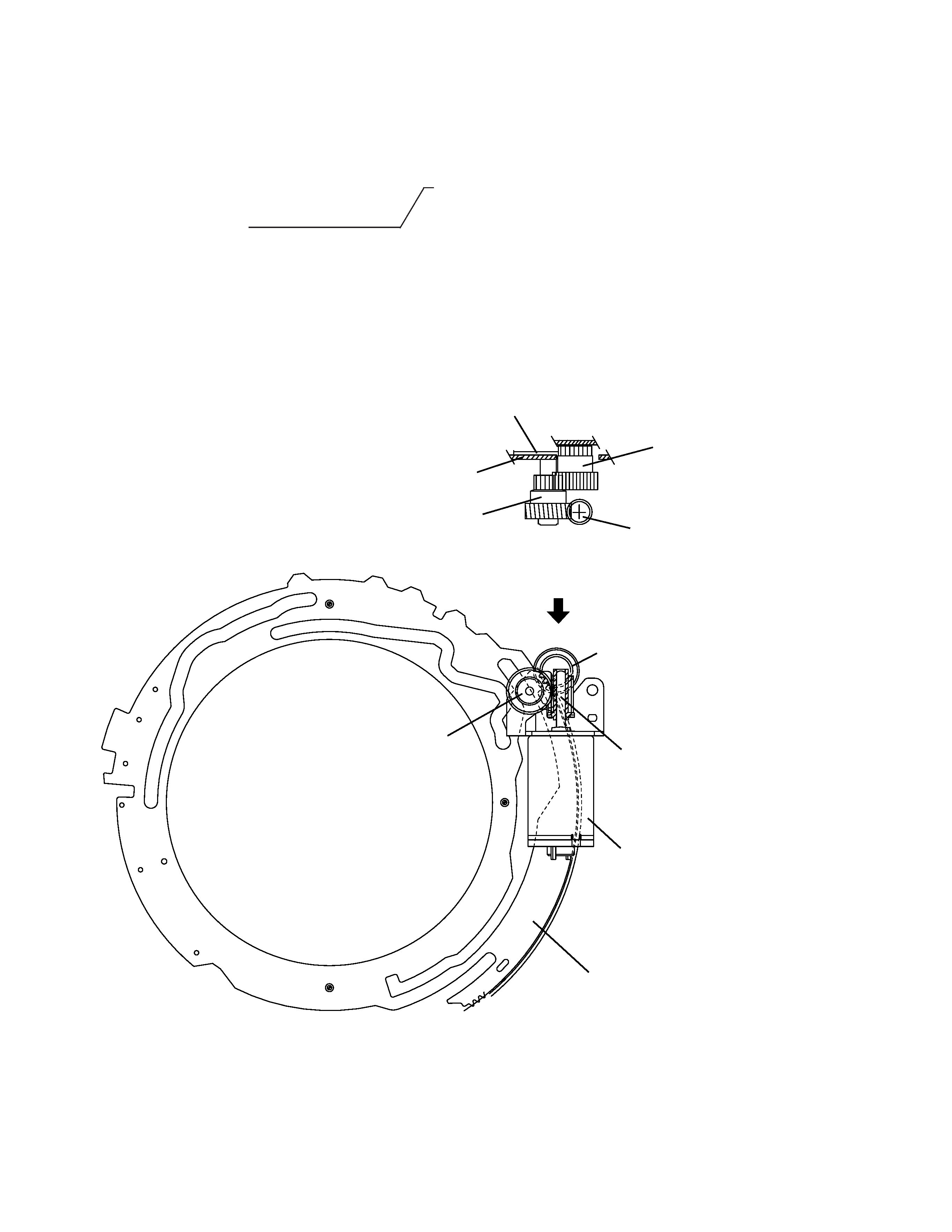
Inserting the cassette tape t Draw in t Put in down tRelease rt Forward play rt REW rt FF rt Reverse play
Eject r Draw out r Lift r
All motive force(except that for tape running) is supplied by the sub-motor.
All the operation modes including tape insertion and ejection are switched via the mode gear.
Mode gear
Pre mode gear
Chassis
Worm wheel
Worm gear
Pre mode gear
Worm wheel
Worm gear
Mode gear
Sub motor
A
CX-1011
3
Draw-in arm
Draw-in lever
Load buffer lever
Load switch
Load drive lever
Cassette tape
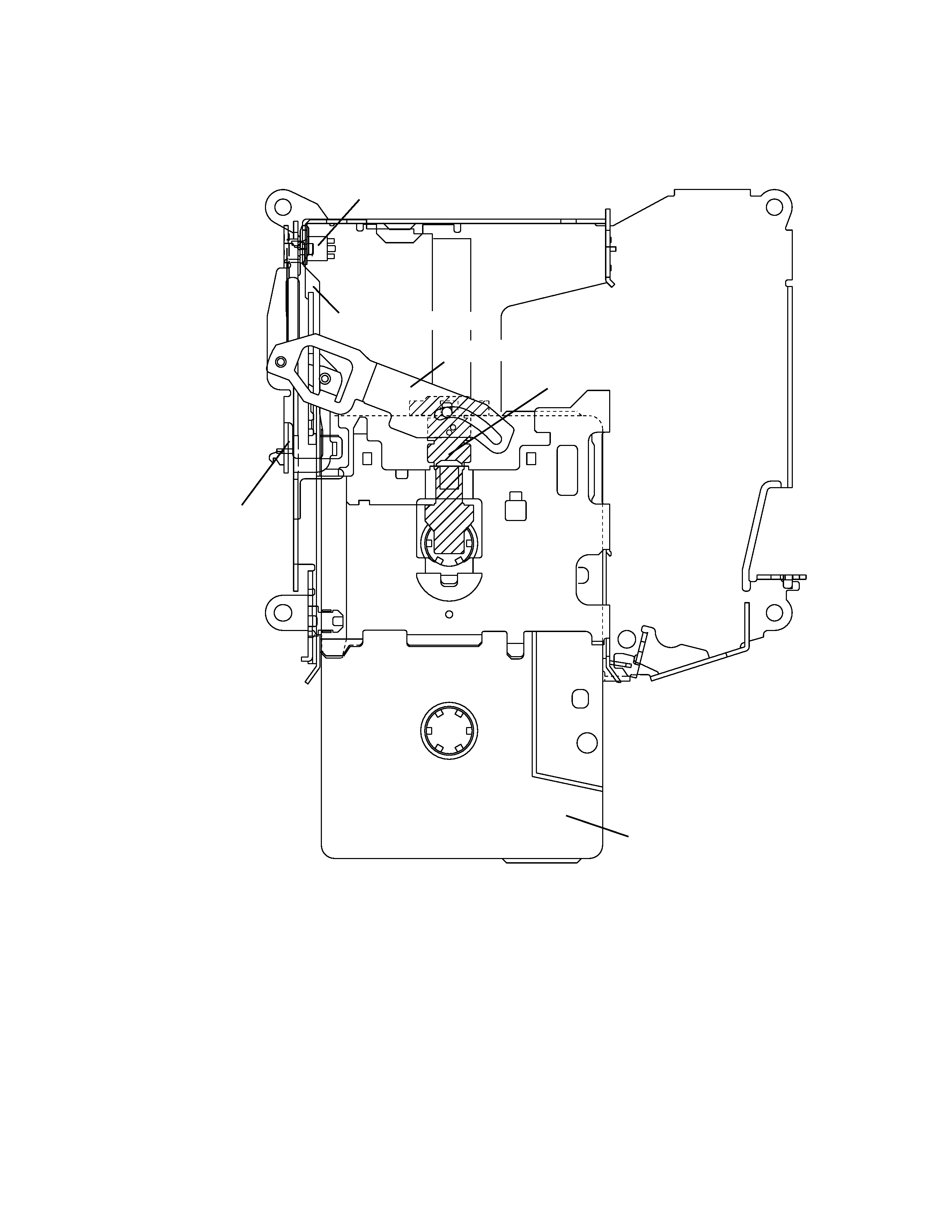
1.2 LOADING AND EJECT OPERATIONS(1)
- Loading operation
1. Insert a cassette tape into the slot.
2. The cassette tape pushes the draw-in lever. Then the load switch is turned ON via the draw-in arm and load buffer
lever.
3. The sub motor starts running.
4. The sub motor turns the mode gear. Then the mode gear moves the load drive lever and load buffer lever.
5. The shaft holder of the load buffer lever rotates the draw-in arm to draw in the cassette tape.
- Eject operation
1. The cassette tape is ejected in accordance with the reverse of the loading operations. After that, the load switch is
turned OFF and the sub motor stops rotating.
4
CX-1011
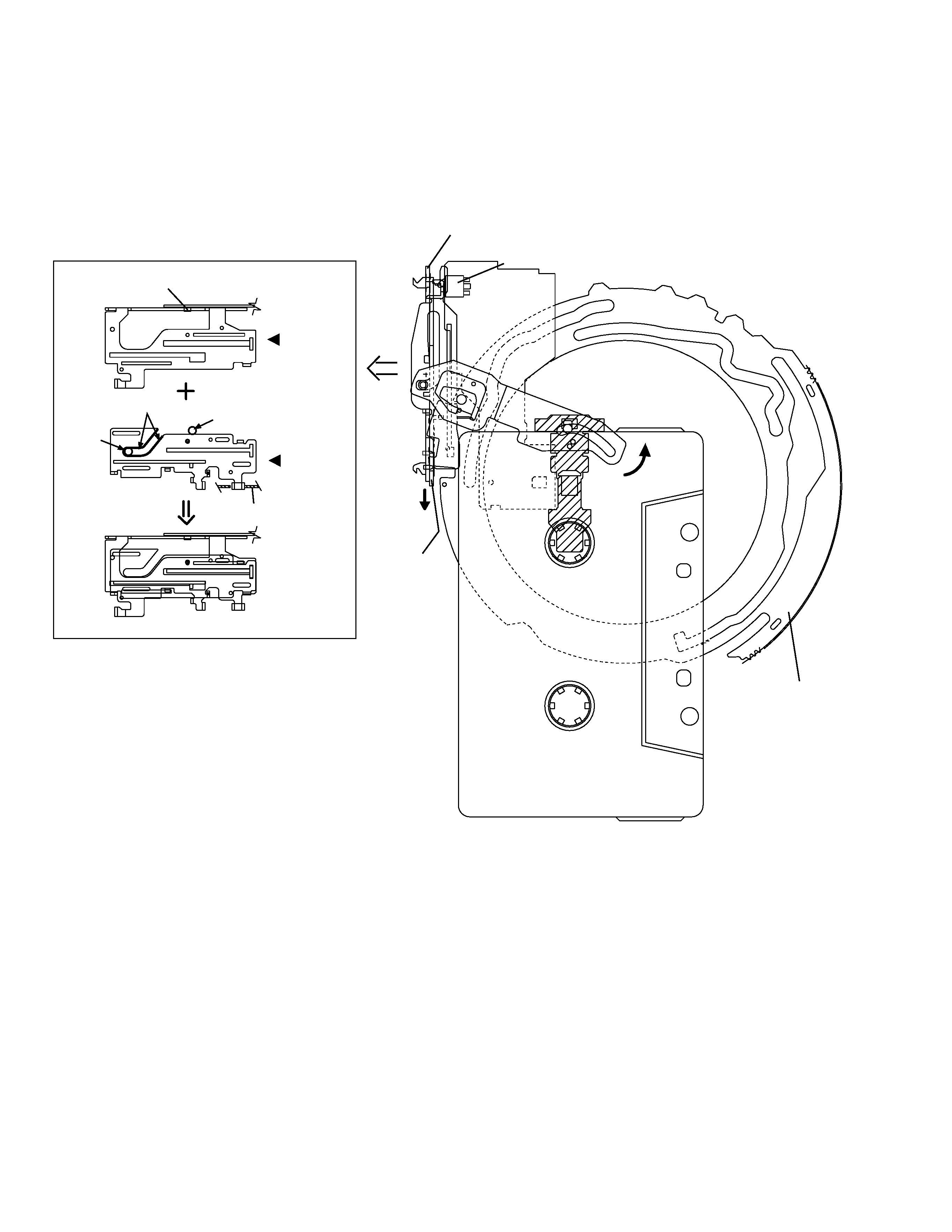
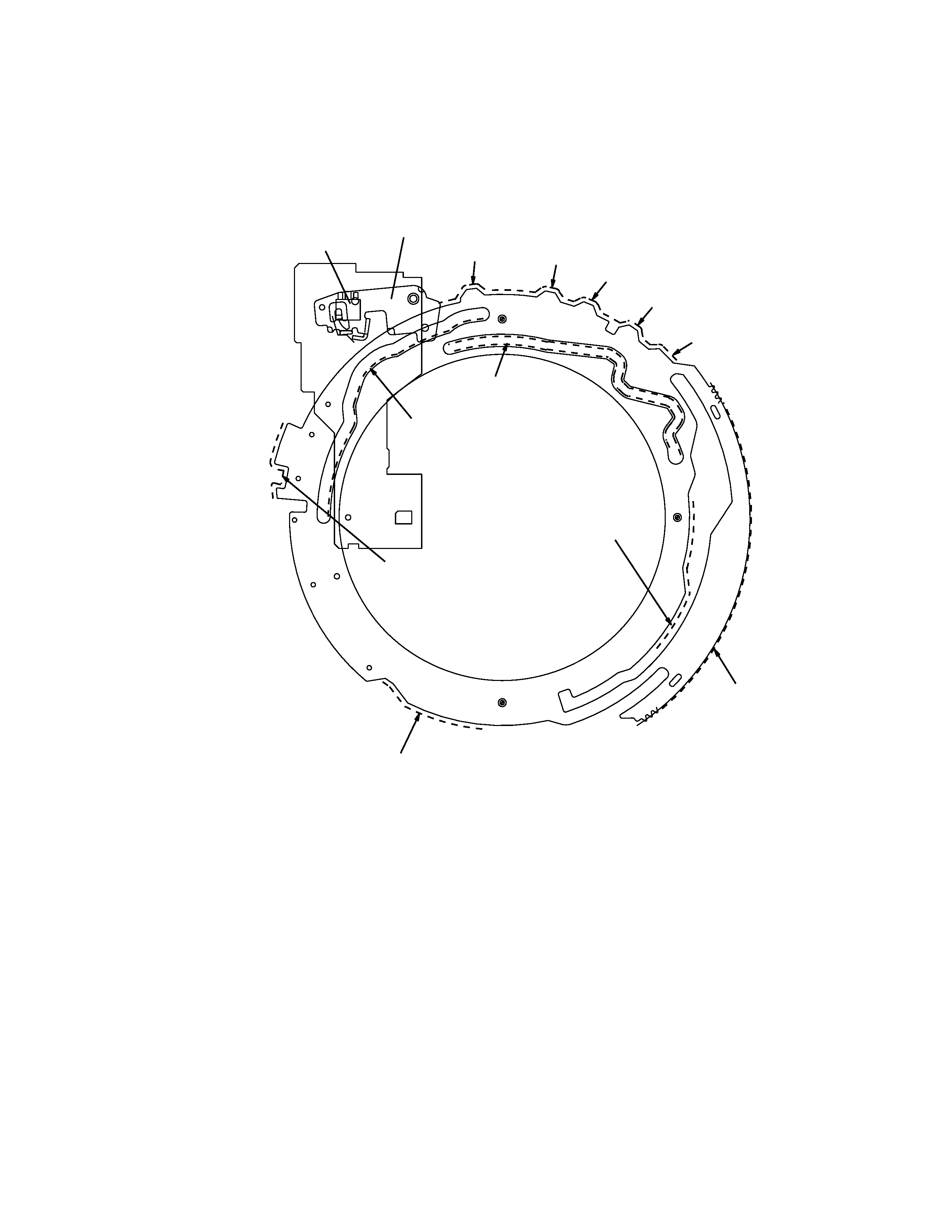
1.3 LOADING AND EJECT OPERATIONS(2)
- Loading operation
1. When the mode gear rotates, the load drive lever moves in the direction B marked with an arrow in the figure.
2. As the load buffer lever is linked with the load drive lever via a spring, the load buffer lever turns the draw-in arm
in the cassette.
- Eject operation
1.
Eject operation is done in accordance with the reverse of the loading operation.
Load switch
Load buffer lever
Load
drive lever
Mode gear
B
Load
buffer lever
Load
drive lever
Draw-in arm bearing
Mode gear
Lift position
Put-down Lift cam
Put-down
position
5
CX-1011
1.4 MODE CHANGEOVER
Mode switch
mode arm
Head base position
changeover
F/R idler gear
changeover
Load-leber
drive cam
Reverse pinch roller
changeover
Foward pinch roller
changeover
Drive
(REV)
(FF)
(REW)
(FWD)
(Release)
The mode gear is rotated by rotation of the pre mode gear which is driven by the sub-motor.
The modes are in series in the order of "release"rt"forward play"rt"REW"rt"FF"rt"reverse play".
The rotation of the mode gear makes changeover of the head position, press contact between the pinch rollers(for-
ward, reverse), the rewinding reel rotation, etc.
The actions to be performed in the separate mode are show in Fig.1 through 5.
