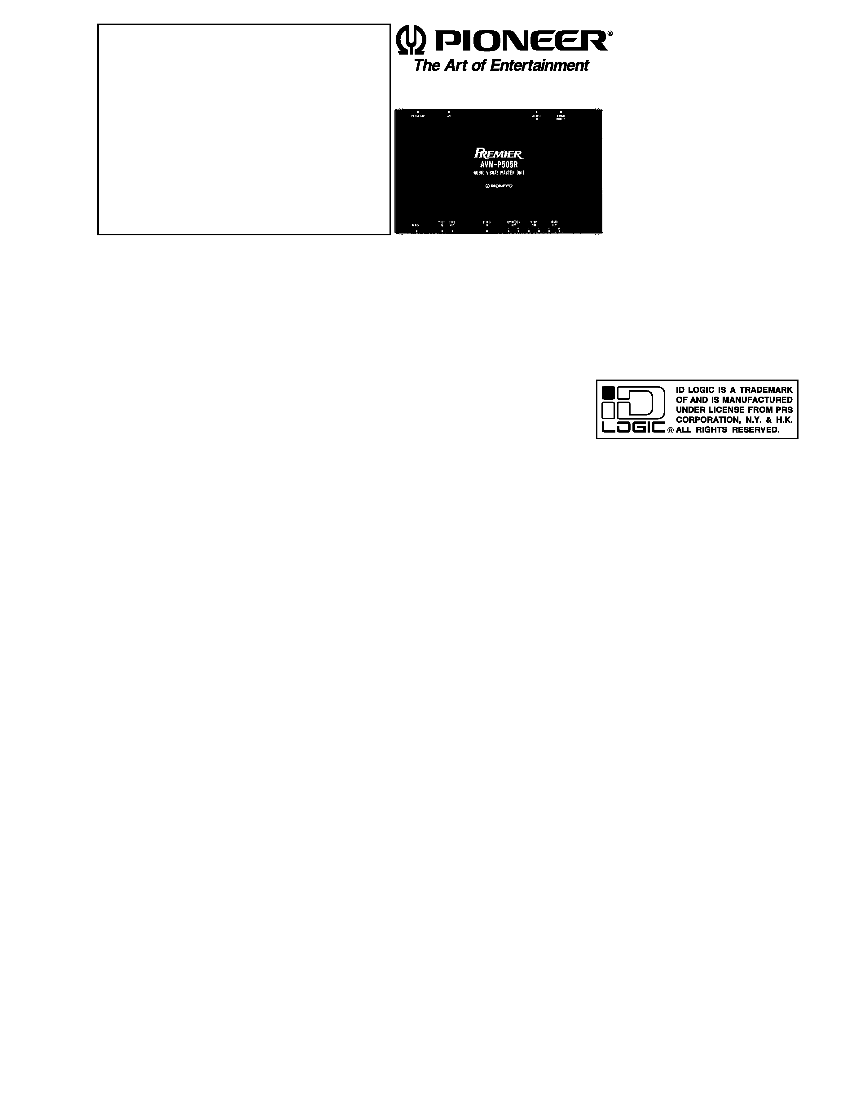
AUDIO VISUAL MASTER UNIT
AVM-P505R
UC
Service
Manual
PIONEER ELECTRONIC CORPORATION
4-1, Meguro 1-Chome, Meguro-ku, Tokyo 153-8654, Japan
PIONEER ELECTRONICS SERVICE INC.
P.O.Box 1760, Long Beach, CA 90801-1760 U.S.A.
PIONEER ELECTRONIC [EUROPE] N.V.
Haven 1087 Keetberglaan 1, 9120 Melsele, Belgium
PIONEER ELECTRONICS ASIACENTRE PTE.LTD. 501 Orchard Road, #10-00, Lane Wheelock Place, Singapore 238880
C PIONEER ELECTRONIC CORPORATION 1998
ORDER NO.
CRT2215
CONTENTS
1. SAFETY INFORMATION ............................................2
2. EXPLODED VIEWS AND PARTS LIST .......................2
3. SCHEMATIC DIAGRAM .............................................6
4. PCB CONNECTION DIAGRAM ................................14
5. ELECTRICAL PARTS LIST ........................................20
6. ADJUSTMENT..........................................................29
7. GENERAL INFORMATION .......................................31
7.1 IC ........................................................................31
7.2 BLOCK DIAGRAM ..............................................36
8. OPERATIONS AND SPECIFICATIONS.....................38
K-FED. JUNE 1998 Printed in Japan

2
AVM-P505R
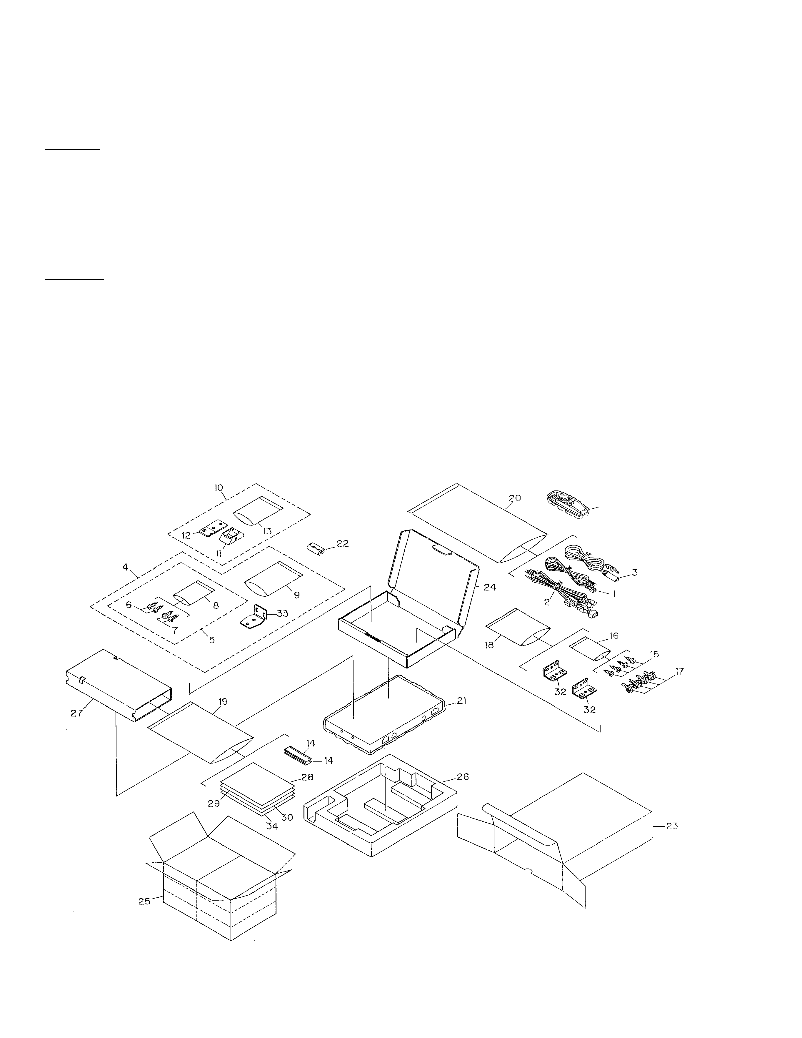
2. EXPLODED VIEWS AND PARTS LIST
2.1 PACKING
31
CAUTION
This service manual is intended for qualified service technicians; it is not meant for the casual do-it-yourselfer.
Qualified technicians have the necessary test equipment and tools, and have been trained to properly and safely repair
complex products such as those covered by this manual.
Improperly performed repairs can adversely affect the safety and reliability of the product and may void the warranty.
If you are not qualified to perform the repair of this product properly and safely; you should not risk trying to do so and
refer the repair to a qualified service technician.
WARNING
Lead in solder used in this product is listed by the California Health and Welfare agency as a known reproductive
toxicant which may cause birth defects or other reproductive harm (California Health and Safety Code, Section
25249.5). When servicing or handling circuit boards and other components which contain lead in solder, avoid
unprotected skin contact with the solder. Also, when soldering do not inhale any smoke or fumes produced.
1. SAFETY INFORMATION

3
AVM-P505R
NOTE:
- Parts marked by "*"are generally unavailable because they are not in our Master Spare Parts List.
- Screws adjacent to
Ñ mark on the product are used for disassembly.
1 Cord
CDE5579
2 Cord Assy
CDE5583
3 Antenna Cable
CDH1248
4 Bracket Assy
CEA2346
5 Screw Assy
CZE3198
6 Screw
BNC40P120FZK
7 Screw
BPZ30P100FZK
*
8 Polyethylene Bag
CEG-127
*
9 Polyethylene Bag
CZE3201
10 Base Assy
CEA2426
*
11 Base
CNS5031
*
12 Sheet
CZA3371
13 Polyethylene Bag
CZE3188
14 Fastener
CNM3728
15 Screw
BNC40P120FZK
*
16 Polyethylene Bag
CEG1158
17 Screw
HMF40P080FZK
*
18 Polyethylene Bag
CEG1101
19 Polyethylene Bag
CEG1116
20 Polyethylene Bag
CEG1162
21 Polyethylene Bag
CEG1185
22 Battery
CEX1006
23 Carton
CHG3512
24 Sub Carton
CHG3521
25 Contain Box
CHL3512
26 Protector
CHP2055
27 Inner Box
CHW1712
28 Owner's Manual
CRD2715
(English, French)
29 Installation Manual
CRD2716
(English, French)
*
30 Warranty Card
CRY1070
31 Remote Control Assy
CXB2657
32 Angel
CNB2351
33 Bracket
CZN6467
34 Caution Card
CRP1188
- PACKING SECTION PARTS LIST
Mark No. Description
Part No.
Mark No. Description
Part No.

4
AVM-P505R
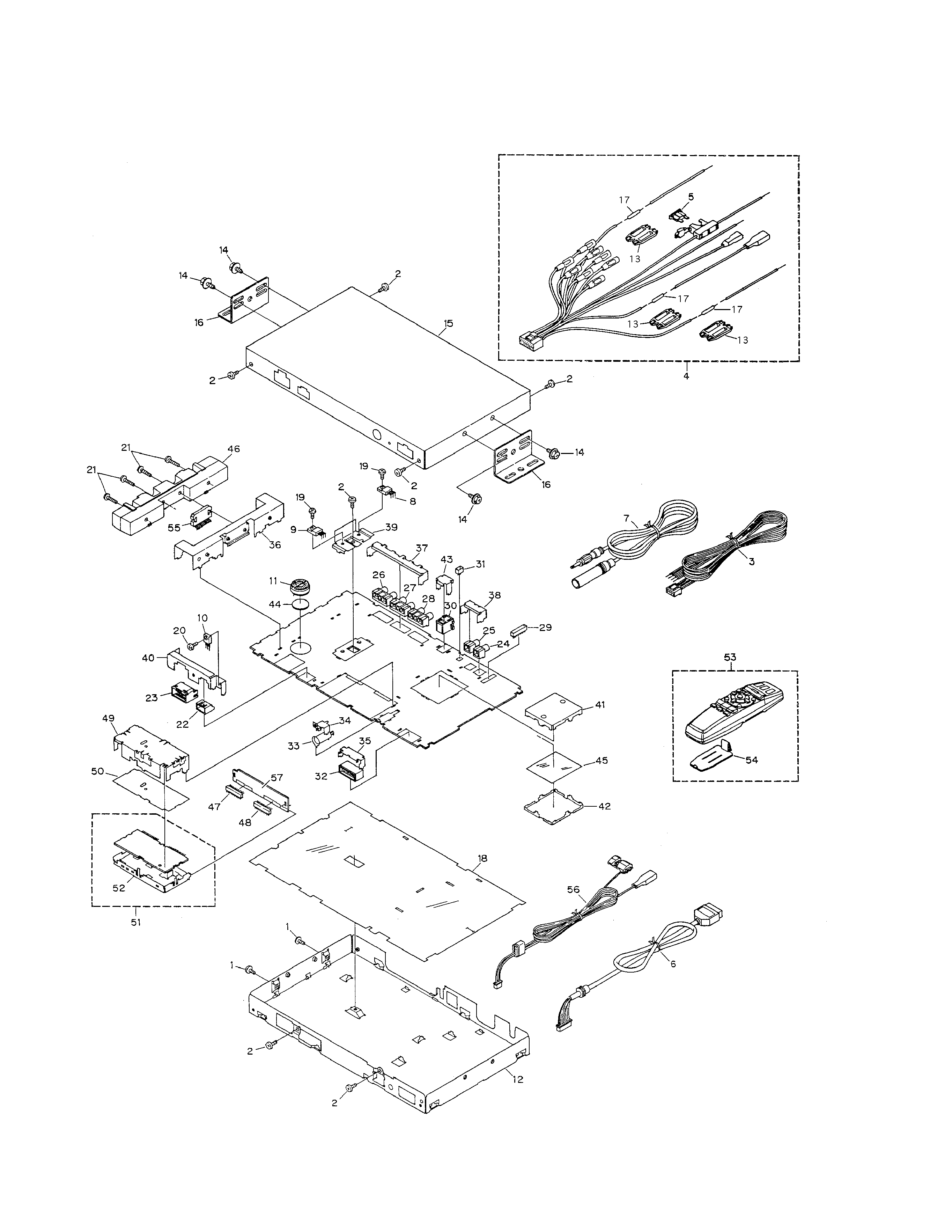
2.2 EXTERIOR

5
AVM-P505R
1 Screw
BMZ30P060FMC
2 Screw
BSZ30P060FZK
3 Cord
CDE5579
4 Cord Assy
CDE5583
5 Fuse
CEK1136
6 Cord Assy
CDE5677
7 Antenna Cable
CDH1248
8 Transistor(Q941)
2SD2396
9 Transistor(Q881)
2SD2396
10 Transistor(Q891)
2SD2343
11 Coil(L901)
CTH1170
12 Chassis
CNA2035
13 Cap
CNS1472
14 Screw
HMF40P080FZK
15 Case
CNB2290
16 Angle
CNB2351
17 Resistor
RS1/2PMF102J
18 Insulator
CNM5700
19 Screw
BMZ26P060FMC
20 Screw
BSZ26P080FZK
21 Screw
BSZ26P160FMC
22 Plug(CN131)
CKM1131
23 Plug(CN901)
CKM1278
24 Pin Jack(CN1301)
CKS1825
25 Pin Jack(CN1302)
CKS1825
26 Pin Jack(CN351)
CKS3144
27 Pin Jack(CN352)
CKS3144
28 Pin Jack(CN353)
CKS3144
29 Plug(CN1001)
CKS3282
30 Connector(CN102)
CKS3414
31 Connector(CN961)
CKS3582
32 Connector(CN1101)
CKS3644
33 Antenna Jack(CN501)
CKX1056
34 Holder
CNC4569
35 Holder
CNC7047
36 Holder
CNC7630
37 Holder
CNC7632
38 Holder
CNC7633
39 Holder
CNC7634
40 Holder
CNC7635
41 Shield
CNC7636
42 Shield
CNC7637
43 Holder
CNC7838
44 Insulator
CNM3634
45 Insulator
CNM5699
46 Heat Sink
CNR1472
47 Plug(CN1402)
CKS1621
48 Plug(CN1403)
CKS1621
49 Holder
CNC7631
50 Insulator
CNM4684
51 FM/AM Tuner Unit
CWE1472
52 Holder
CNC6554
53 Remote Control Assy
CXB2657
54 Battery Cover
CNS5032
55 IC(IC171)
TDA7386
56 Cord Assy
CDE5581
*
57 Gathering PCB
CNX2873
- EXTERIOR SECTION PARTS LIST
Mark No. Description
Part No.
Mark No. Description
Part No.
