AVIC-S2/XZ/EW5
ORDER NO.
CRT3966
PORTABLE NAVIGATION UNIT
PIONEER CORPORATION
4-1, Meguro 1-Chome, Meguro-ku, Tokyo 153-8654, Japan
PIONEER ELECTRONICS (USA) INC. P.O.Box 1760, Long Beach, CA 90801-1760 U.S.A.
PIONEER EUROPE NV Haven 1087 Keetberglaan 1, 9120 Melsele, Belgium
PIONEER ELECTRONICS ASIACENTRE PTE.LTD. 253 Alexandra Road, #04-01, Singapore 159936
APR. 2007 Printed in Japan
Contents
3
3
3
4
6
7
10
10
12
21
21
1. Product Introduction
1.1 System Overview
1.2 Product Specification
2. Software Upgrade
2.1 Uboot Upgrade
2.2 Image Upgrade
3. Service Diagnostics and Trouble Shooting
-----------------
---
--------------------
-----------------------
-----------------
----------------
----------------------
-----------------------
---------------------
-----------------------------
--------------------------------
-----------------------------
-------------------------
-----------------------
-----------------------
-----------------------
-----------------------
-----------------------------
3.1 Power On Test
3.2 Mini USB Test
3.3 D.M. Test
4. System View & Disassembly
4.1 Tools Introduction
4.2 System View
4.3 System Disassembly
13
22
23
27
29
30
5. Technical FAQ
6. Recommend Spare Parts List
7. System Exploded Views
28
8. Service Parts List
AVIC-S2
2
4
2
1
C
D
F
A
B
E
3
4
2
1
3
[Important Check Points for Good Servicing]
In this manual, procedures that must be performed during repairs are marked with the below symbol.
Please be sure to confirm and follow these procedures.
1. Product safety
Please conform to product regulations (such as safety and radiation regulations), and maintain a safe servicing environment by
following the safety instructions described in this manual.
1 Use specified parts for repair.
Use genuine parts. Be sure to use important parts for safety.
2 Do not perform modifications without proper instructions.
Please follow the specified safety methods when modification(addition/change of parts) is required due to interferences such as
radio/TV interference and foreign noise.
3 Make sure the soldering of repaired locations is properly performed.
When you solder while repairing, please be sure that there are no cold solder and other debris.
Soldering should be finished with the proper quantity. (Refer to the example)
4 Make sure the screws are tightly fastened.
Please be sure that all screws are fastened, and that there are no loose screws.
5 Make sure each connectors are correctly inserted.
Please be sure that all connectors are inserted, and that there are no imperfect insertion.
6 Make sure the wiring cables are set to their original state.
Please replace the wiring and cables to the original state after repairs.
In addition, be sure that there are no pinched wires, etc.
7 Make sure screws and soldering scraps do not remain inside the product.
Please check that neither solder debris nor screws remain inside the product.
8 There should be no semi-broken wires, scratches, melting, etc. on the coating of the power cord.
Damaged power cords may lead to fire accidents, so please be sure that there are no damages.
If you find a damaged power cord, please exchange it with a suitable one.
9 There should be no spark traces or similar marks on the power plug.
When spark traces or similar marks are found on the power supply plug, please check the connection and advise on secure
connections and suitable usage. Please exchange the power cord if necessary.
0 Safe environment should be secured during servicing.
When you perform repairs, please pay attention to static electricity, furniture, household articles, etc. in order to prevent injuries.
Please pay attention to your surroundings and repair safely.
2. Adjustments
To keep the original performance of the products, optimum adjustments and confirmation of characteristics within specification.
Adjustments should be performed in accordance with the procedures/instructions described in this manual.
4. Cleaning
For parts that require cleaning, such as optical pickups, tape deck heads, lenses and mirrors used in projection monitors, proper
cleaning should be performed to restore their performances.
3. Lubricants, Glues, and Replacement parts
Use grease and adhesives that are equal to the specified substance.
Make sure the proper amount is applied.
5. Shipping mode and Shipping screws
To protect products from damages or failures during transit, the shipping mode should be set or the shipping screws should be
installed before shipment. Please be sure to follow this method especially if it is specified in this manual.
AVIC-S2
3
5
7
8
C
D
F
A
B
E
6
5
7
8
6
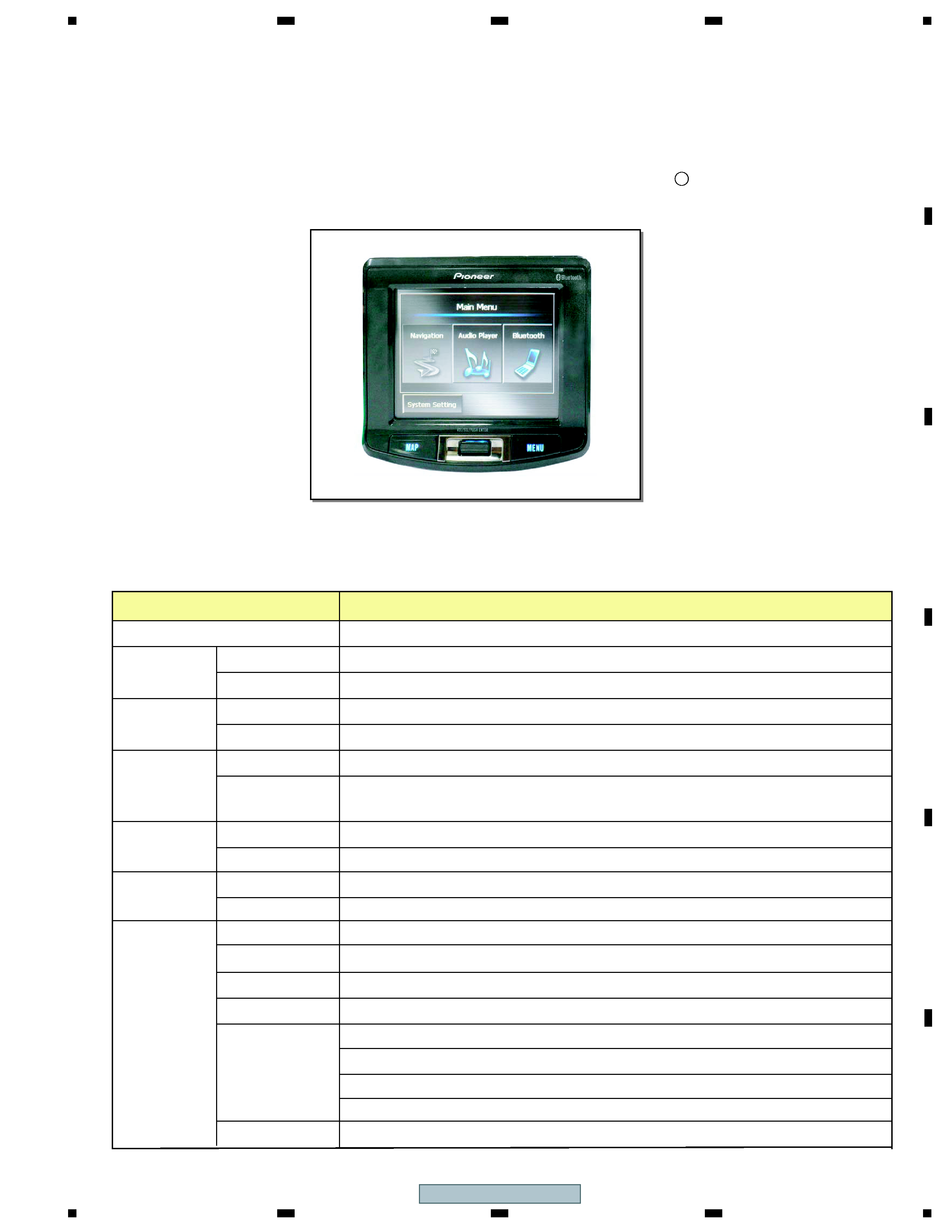
1.1 System Overview
This document describes the electrical functionality of AVIC-S2, which is a Personal Navigation
Device (PND)
based on Samsung S3C2440A, 400MHz SOC and Microsoft Windows R CE.Net 5.0 core version
OS. (Figure 1-1)
1. Product Introduction
Figure 1-1 AVIC-S2 Overview
1.2 Product Specification (1)
One Omni micophone to be located in the main unit.
Microphone
Navi-wheel (up/down/enter)
Scroll Wheel
Mini-B USB, for USB and AC adaptor
USB Connector
CPU, USB 1,1 client
IC
USB
Embedded pifa antenna
Antenna
CSR BC4-ROM, BT1.1
IC
Bluetooth
Antenna
IC
Power On/Off
Button/Switch
Reset
Cold-boot switch
Navigation Menu (Destination), button, MAP button for current position or cancel
One phone jack
Phone Jack
Resistive type Touch panel
Touch Panel
User
Input/Output
SiRFStar III
Speaker
GPS
RAM
ROM
Resolution
Display
256MB NAND Flash on board, 1GB (for UC, EW5)/512 MB(for RE, AU) SD card accessory
Memory
Video
Embedded patch antenna with extended antenna jack, 15mm x 15mm
An external antenna jack is also present
64MB SDRAM
3.5' Color TFT LCD, LED Backlight, Hitachi
Samsung S3 C2440A SOC, 400MHz
CPU
Built-in loud speaker x 1 (0.9W), 28mm
320 x 240, 64K colors, QVGA resolution, Landscape
Specification
Function
AVIC-S2
4
4
2
1
C
D
F
A
B
E
3
4
2
1
3
1.2 Product Specification (2)
Output
Car Charger
Charging
Suspension
For 1GBSD card with MAP and support MP3 running
SD Slot
LED Indicator
-30~80
-10~60
Temperature
Environment
Input
Output
Active
Input
Type
AC toDC
Adapter
Battery
Contactconnector on rear side to connect to cradle
Specification
Car Kit Connector
Function
Operation System
Software
Charger LED (dual-color): amber n battery charging green n battery full
Bluetooth LED: blue
Keypad LED: blue
Un-swappable rechargeable Lithium-Ion battery cell, 1200 mAH (TBC) (battery
package provided by cell vendor)
4 hours (GPS with default backlight)
21 days (fully charged main battery)
AC charging: under 4 hours (system off)
AC charging: under 5 hours (system on)
100 n 240VAC
5VDC, 1A
10 ~ 30V, 1.3A Max
5V, 1A
Operation
Storage
Microsoft Windows R CE .Net 5.0 Core version (work with Navigation)
2. Software Upgrade
2.1 Uboot Upgrade
2.1.1 By USB Cable
1. Setup the USB driver in the computer.
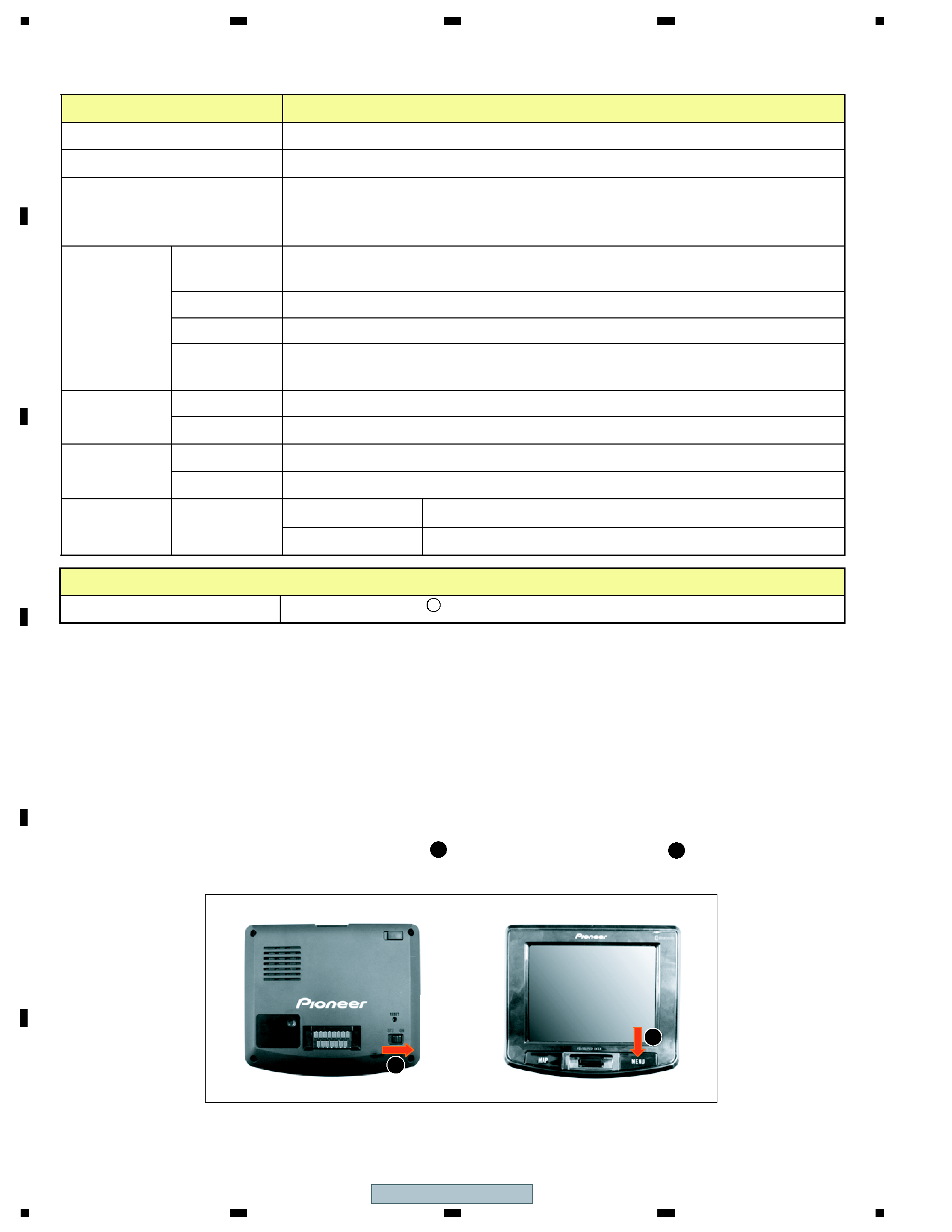
2. Push the "Cold Boot" swtch to "ON" status ( ) and press the "Menu" button ( ) to enter the
Uboot interface. (Figure 2-1)
Tools:
Hardware:
1. Computer
2. Mini USB cable
Software:
1. USB driver
2 . dnw.exe
3. Ubootf ile
1
2
Figure 2-1 Enter the "UBoot" interface
2
1
AVIC-S2
5
5
7
8
C
D
F
A
B
E
6
5
7
8
6
Figure 2-2 Se lect " 0 =UBOOT b y US B" item
3. Please connect the AVIC-S2 to the computer by mini USB cable.
4. Select "3=UBOOT Upgrade" item in "GSII_R03. 1200.0207 256MB" menu, then select "1=UBOOT by USB"
item in "UBOOT Upgrade" menu and press the key to act. (Figure 2-2)
Note: Depend on the build-in ROM of quotas , the UBOOT will show up the correct one.
GSII_R03.1200.0207 256MB
0=WINCE Upgrade
1=GPS Tools
3=UBOOT Upgrade
4=Memory Tools
Choice: 3
2=BT Test
0=UBOOT by SD/MMC
1=UBOOT by USB
2=Exit
Choice: 1
UBOOT Upgrade
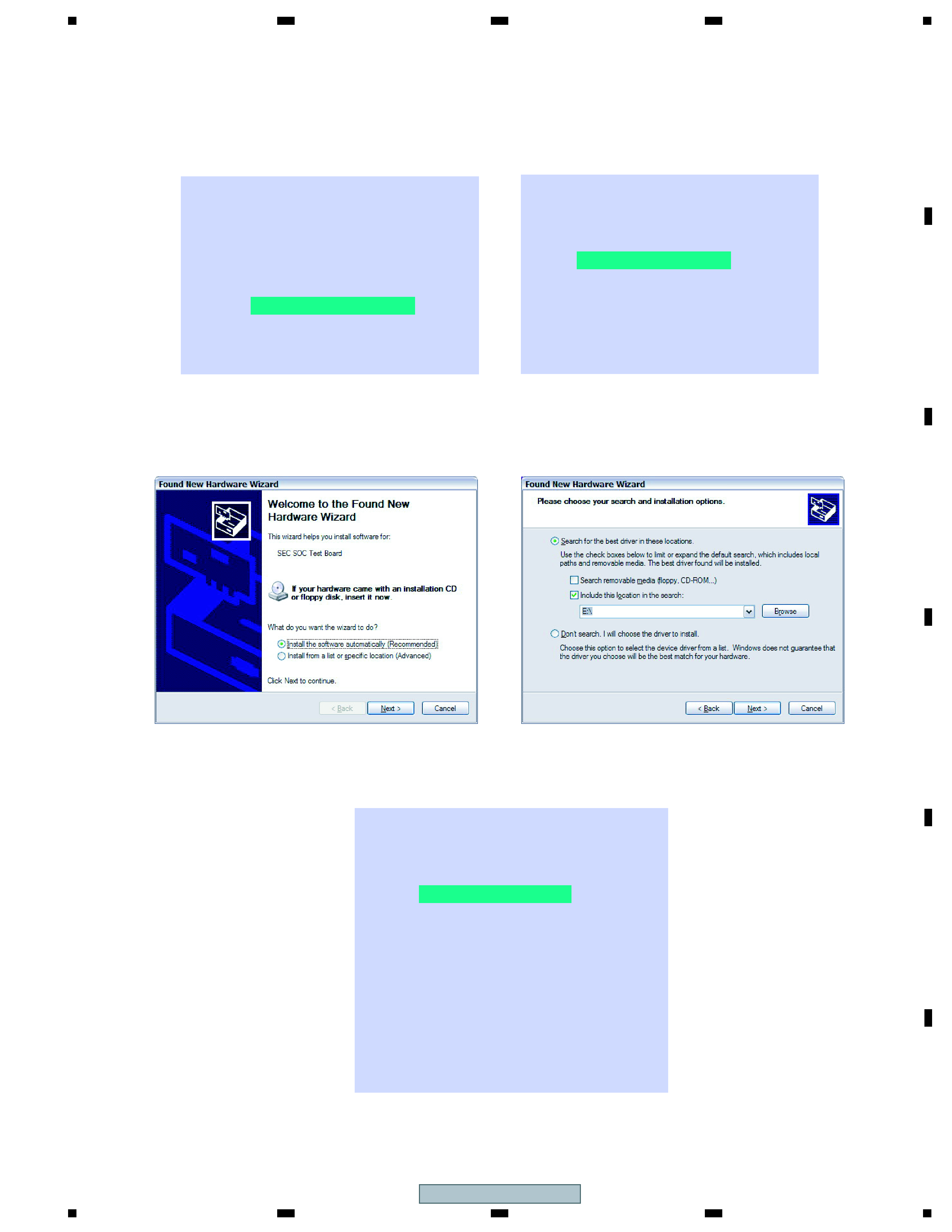
5. If the computer has found the new hardware, please follow the wizard to install the deviceís driver (secbulk.inf).
(Figure 2-3)
Figure 2-3 Setup the driver
6. If the driver setup OK at the computer side, the AVIC-S2 will display "USB Cable connected". (Figure 2-4)
Figure 2-4 USB Cable connected
Uboot Upgrade
downAddr : 30025020
Waiting for download Ö
Cable not connected.
USB Cable connected.
0=UBOOT by SD/MMC
1=UBOOT by USB
2=Exit
Choice: 1
UBOOT Upgrade
