CR-305TX
SERVICE MANUAL
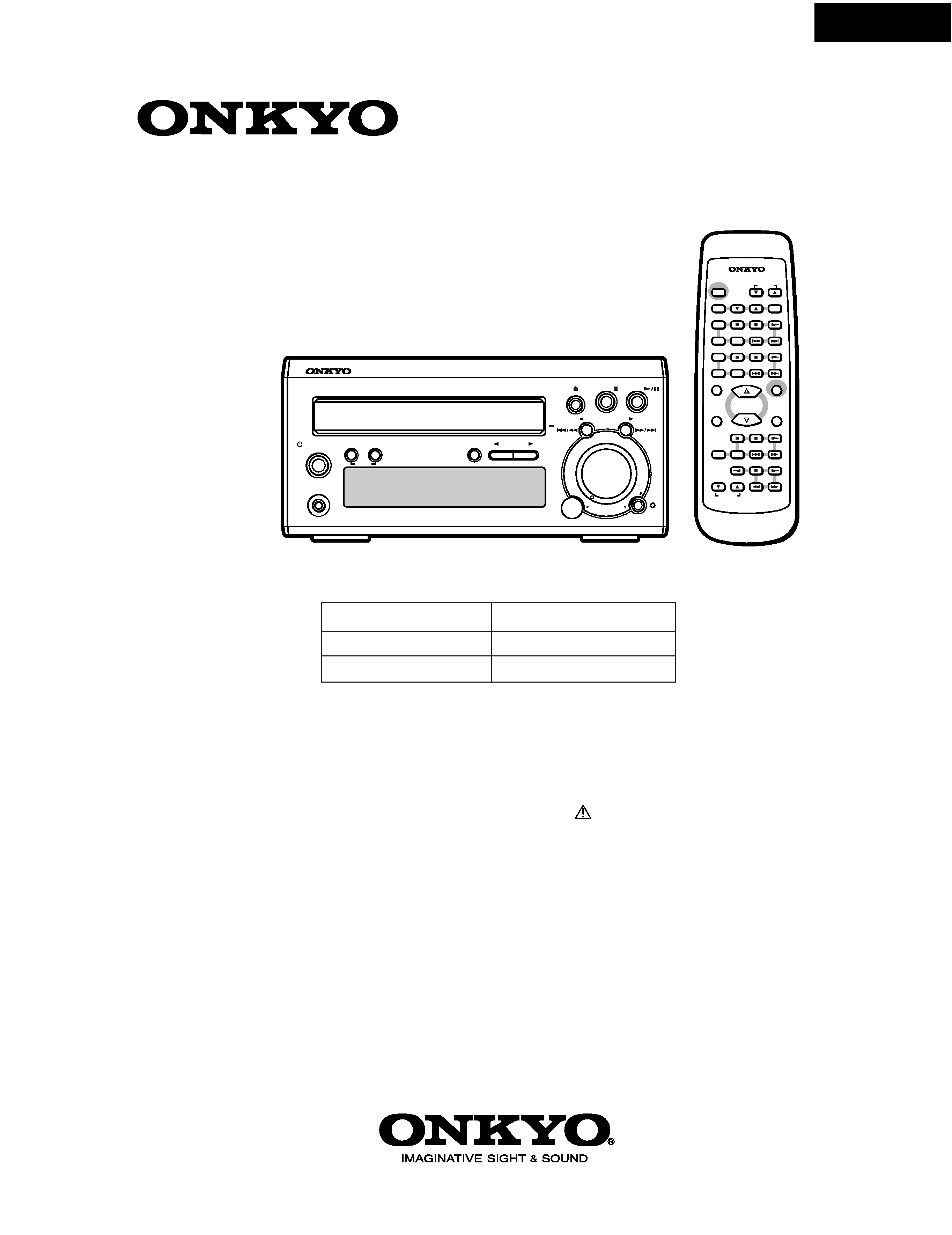
CD RECEIVER
Silver model
MODEL
CR-305TX
120V AC, 60Hz
220-230V AC, 50Hz
230-240V AC, 50Hz
UDD,UDT
UGT,UGR,
UPP
Ref. No. 3723
062002
RC-421S
DISPLAY
TUNING/PRESET
STANDBY/ON MEMORY FM MODE
CLEAR
PHONES
A
C
O
U
S
T
IC
P
R
E
S
E
N
C
E
INPUT
A
C
O
U
S
T
IC
P
R
E
S
E
N
C
E
VOLUME
MAX
MIN
VOL
UME UP
VO
LUME DOW
N
REMOTE CONTROLLER
STANDBY/ON
INPUT
TIMER
ENTER
RANDOM
MEMORY REPEAT
CD
PLAY MODE
SLEEP
A.PRESENCE
CLOCK
CALL
MUTING
REPEAT
MD
VOLUME
PLAY MODE REPEAT
TUNER
PRESET
CDR
TAPE
SCROLL
RC-421S
SAFETY-RELATED COMPONENT
WARNING!!
COMPONENTS IDENTIFIED BY MARK
ON THE
SCHEMATIC DIAGRAM AND IN THE PARTS LIST ARE
CRITICAL FOR RISK OF FIRE AND ELECTRIC SHOCK.
REPLACE THESE COMPONENTS WITH ONKYO
PARTS WHOSE PART NUMBERS APPEAR AS SHOWN
IN THIS MANUAL.
MAKE LEAKAGE-CURRENT OR RESISTANCE
MEASUREMENTS TO DETERMINE THAT EXPOSED
PARTS ARE ACCEPTABLY INSULATED FROM THE
SUPPLY CIRCUIT BEFORE RETURNING THE
APPLIANCE TO THE CUSTOMER.

CR-305TX
SERVICE PROCEDURES-1
PROTECTION OF EYES FROM LASER BEAM DURING SERVICING
This set employs a laser. Therefore, be sure to follow
carefully the instructions below when servicing.
WARNING!!
SERVICE WARNING : DO NOT APPROACH THE
LASER EXIT WITH THE EYE TOO CLOSELY.
IN CASE IT IS NECESSARY TO CONFIRM LASER
BEAM EMISSION, BE SURE TO OBSERVE FROM
A DISTANCE OF MORE THAN 30cm FROM THE
SURFACE OF THE OBJECTIVE LENS ON THE
OPTICAL PICKUP BLOCK.
Laser Diode Properties
Material: GaAS/GaAlAs
Wavelength: 780nm
Laser output: max. 0.5mW*
Emission Duration: continuous
*This output is the value measured at a distance about 1.8mm
from the objective lens surface on the Optical Pickup Block.
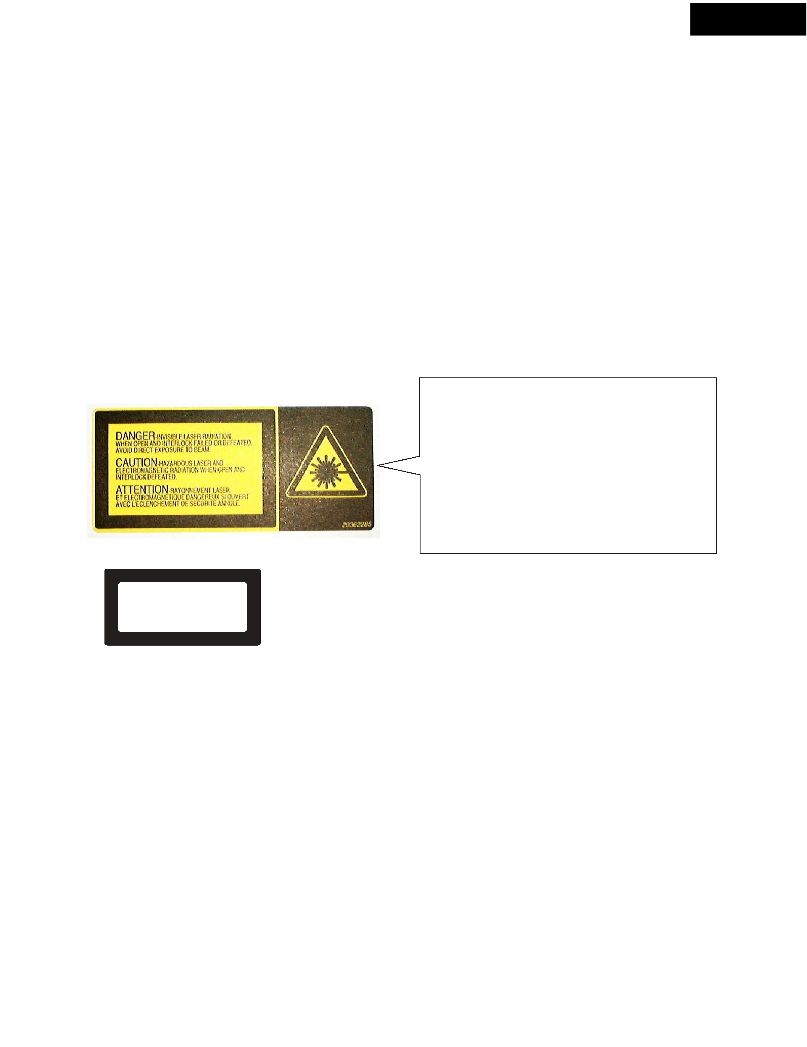
LASER WARNING LABEL
The labels shown below are affixed.
1. Warning label
2. Class 1 label
LUOKAN 1
LASERLAITE
KLASS 1
LASER APPARAT
DANGER:
INVISIBLE LASER RADIATION WHEN OPEN AND
INTERLOCK FAILED OR DEFEATED. AVOID DIRECT
EXPOSURE TO BEAM.
"CLASS 1 LASER
PRODUCT"
Printed on rear panel
CAUTION:
HAZARDOUS LASER AND ELECTROMAGNETIC
RADIATION WHEN OPEN AND INTERLOCK DEFEATED.
ATTENTION:
RAYONNEMENT LASER ET ELECTROMAGNETIQUE
DANGEREUX SI OUVERT AVEC L'ECLENCHEMENT
DE SECURITE ANNULE.

CR-305TX
SERVICE PROCEDURES-2
SERVICE PROCEDURES
1. Replacing the fuses
3. Safety-check out
(Only U.S.A. model)
After correcting the original service problem perform the follwing safety check before releasing the set to the customer
Connect the insulating-resistance tester between the plug of power supply cord and terminal GND on the back panel.
Specifications: More than 10Mohm at 500V
REF.NO.
PART NO.
DESCRIPTION
F901
252157
1.25A-UL/T-237, Fuse <DD, DT>
252083
0.4A-SE-EAW, FUSE <PP,GR, GT>
NOTE :
<DD, DT>
: 120 V model only
<PP,GR, GT> : 230 V model only
This symbol located near the fuse indicates that the
fuse used is show operating type, For continued protection against
fire hazard, replace with same type fuse , For fuse rating, refer to
the marking adjest to the symbol.
Ce symbole indique que le fusible utilise est e lent.
Pour une protection permanente, n'utiliser que des fusibles de meme
type. Ce demier est indique la qu le present symbol est apposre.
2. To initialize the unit
4. Memory Preservation
This unit does not require memory preservation batteries. A built-in memory power back-up system preserves the contents of
the memory during power failures and even when the unit is un-plugged.
The unit must be plugged in order to charge the back-up system.
The memory preservation period after the unit has been unplugged varies depending on climate and placement of the unit.
On the average, memory contents are protected over a period of a few weeks after the last time the unit has been unplugged.
This period is shorter when the unit is exposed to a highly humid cli-mate.
5. Changing the AM band step
With the exception of the worldwide models, a tuning step selector switch is not provided.
When you change the band step, change the parts as shown below.
To 10kHz
To 9kHz
R705
3.3k
10k
R706
5.6k
open
1. Press and hold the MEMORY button and press the DISPLAY button.
All segments light up.
2. Press the STANDBY/ON button.
When " CLEAR " appears on the display, the preset memory and each mode stored in the memory are initialized
and will return to the factory setting.

CR-305TX
R
1
8
8
10
11
20,21
13
14
18
16
15
17
SET FRONT
SET FRONT
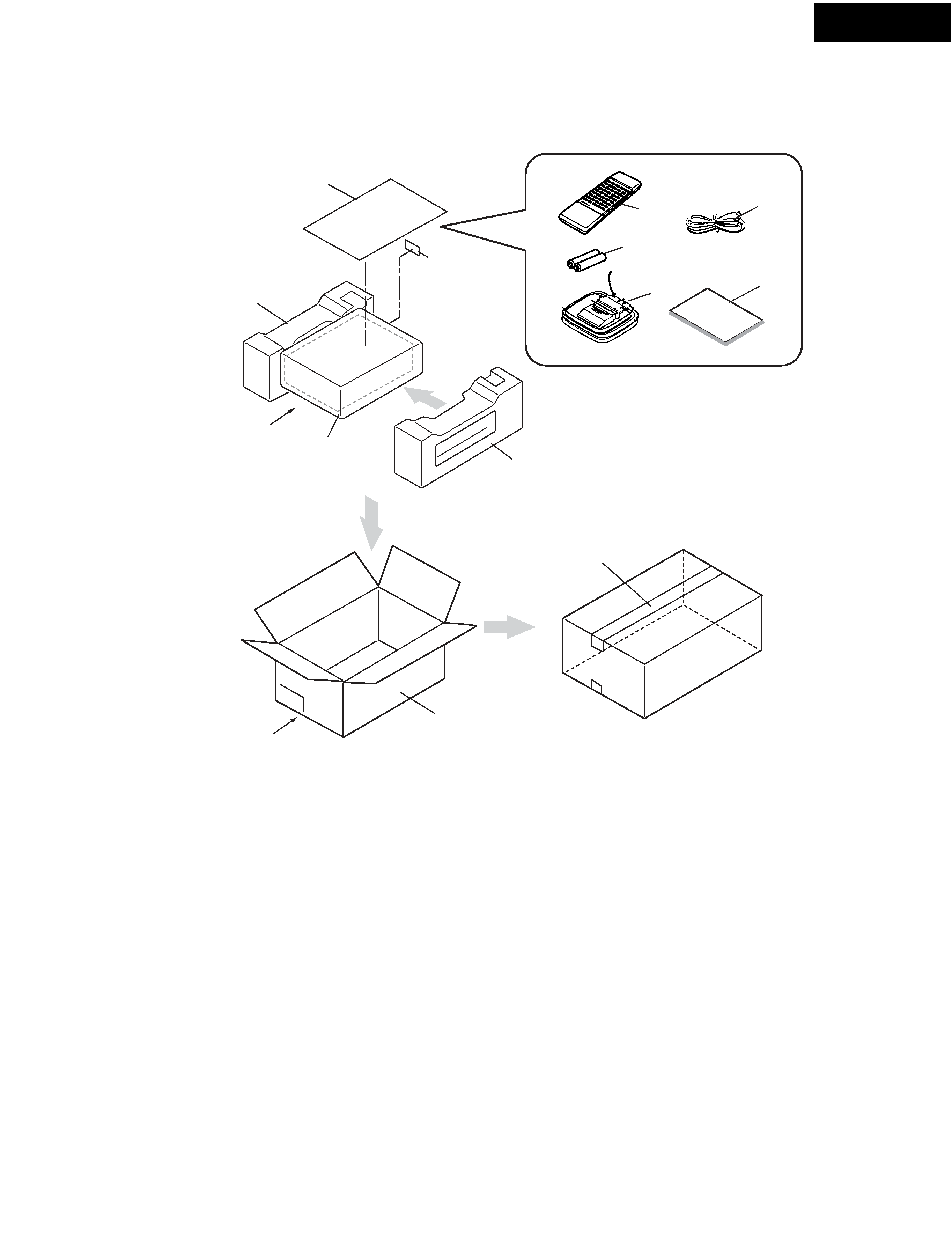
PACKING VIEW
PARTS LIST
1
8
10
11
13
14
15
16
17
18
20
21
REF.NO. PART NO.
DESCRIPTION
REMARKS
6007210450000
6230210504000
29095835
29110149
29110141
24140421
3010054
232140
29100097-1A
292142
292116
5707210600000
5707210600010
5707210600020
26365090
BOX GIFT CR-305TX
CUSHION SNOW EPS
Sheet 0.515 x 650 x 550
Tape
PP Tape
RC-421S, Remote controller
Battery, UM-3
NMA-3057, AM Loop antenna
Poly bag 350 x 250
FM antenna
FM antenna
INSTRUCTION MANUAL E
INSTRUCTION MANUAL FSI
INSTRUCTION MANUAL GDSW
Warranty card
<DD>
<PP>
<PP>
<PP>
<DD>
[NOTE]
<DD> : USA & Canadian model only
<PP>
: European Model only

CR-305TX
NOTE : THE COMPONENTS IDENTIFIED BY MARK
ARE CRITICAL FOR RISK OF FIRE AND
ELECTRIC SHOCK.
REPLACE ONLY WITH
PART NUMBER SPECIFIED.
NOTE:
<DD> : USA and Canadian model only
<PP> : European model only
<DT> : Taiwanese model only
<GT> : Asian model only
<GR> : Chinese model only
PRINTED CIRCUIT BOARD PARTS LIST-1
CIRCUIT NO.
Q401
Q402
Q403,Q404
Q405, Q406
Q409, Q603
Q501-Q504
Q505-Q508
Q509-Q512
Q515-Q518
Q601
Q602
D491,D492
D501-D504
D601
C409,C410
C415-C418
C421,C422
C423,C424,C603
C425,C426
C429,C430
C491,C492
C493,C494
C495,C496
C501,C502
C505,C506,C601
C509-C510
C515,C516
R427
R491,R492
R493,R494
R495
R496
R519-R522
R533,R534
R535,R536
P400, P401
P402
P403B
P404B
JL501A
PART NO.
ICs
22241072
22240981R2
22241383R2
Transistors
2215410R2
2214470R2
2216156R2
2213143R2
2211455 or
2215975
2211455 or
2215975
2213143R2
2214375R2
Diodes
224491300R2
223234R2
223234R2
Capacitors
354742209
371126834
371121534
354780109
371121544
354742209
354742219
354741019
354761019
354741009
354744709
354722219
354741009
Resistors
5104333
443625614
443522204
443521024
443528214
443523904
443523304
443523904
Jacks
25045575
25045581R0
Sockets
25051529
25051234
Plug
25055631
U1:AUDIO PC BOARD (NAAF-6874)
DESCRIPTION
TC9273N-007
TC9162AF
NJM4565M-D
RN1441
RN1402
2SC1622A-L
2SC2712-O
2SA1015-GR or
KTA1266-GR
2SA1015-GR or
KTA1266-GR
2SC2712-O
2SA1162-GR
UDZ13B
1SS352
1SS352
22uF, 16V, Elect.
0.068uF+/-5%, 50V, Plastic
0.015uF+/-5%, 50V, Plastic
1uF, 50V, Elect.
0.15uF5+/-5%, 50V, Plastic
22uF, 16V, Elect.
220uF, 16V, Elect.
100uF, 16V, Elect.
100uF, 35V, Elect.
10uF, 16V, Elect.
47uF, 16V, Elect.
220uF, 6.3V, Elect.
10uF, 16V, Elect.
N16RG100KBT25F, Volume
560ohm+/-5%, 1W, Metal oxide
22ohm+/-5%, 1/2W, Metal oxide
1kohm+/-5%, 1/2W, Metal oxide
820ohm+/-5%, 1/2W, Metal oxide
39ohm+/-5%, 1/2W, Metal oxide
33ohm+/-5%, 1/2W, Metal oxide
39ohm+/-5%, 1/2W, Metal oxide
NPJ-4PDRW389
HSJ1501-010010, RI Jack
NSCT-18P1316
NSCT-9P1024
NPLG-10P593
CIRCUIT NO.
Q901
Q903
Q902
Q904
D901
D902-D908
D909
D910
D911
C904,C905
C907
C909
C913
C914
C918
C920-C924
R901
R903,R913
R907
R908
R911
R912
RL901
JL903B
P901B
P902
JL504B
F901A
P901C
Q903A
Q903B
PART NO.
ICs
222780125
222780565
Transistors
2211503 or
2211504
2213640
Diodes
22380022F or
22380271F
22380260 or
22380035
224492700R2
224490510R2
223234R2
Capacitors
354763329S
354741009
354761019
354764709
3500173S
354781019
374722244
Resistors
443622204
453530224
453534794
443521024
443522704
431533355
Relay
25065607
25065598 or
25065597
Plug
25055624
25055153
25055676
Socket
25050270
Fuse label
29361919
Clamp
27190608-1
Heat sink
27160250
82143010
DESCRIPTION
78M12HF
78M56
2SA950-O or
2SA950-Y
DTC123JS
RBV402 or
D3SBA20
RL1N4003 or
GP104003E
UDZ27B
UDZ5.1B
1SS352
3300uF,35 V, Elect.
10uF, 16V, Elect.
100uF, 35V, Elect.
47uF, 35V, Elect.
6800uF, 16V, Elect.
100uF, 50V, Elect.
0.22uF+/-5%, 50V, Plastic
22ohm+/-5%, 1W, Metal oxide
2.2ohm+/-5%, 1/2W, Metal oxide
0.47ohm+/-5%, 1/2W, Metal oxide
1kohm+/-5%, 1/2W, Metal oxide
27ohm+/-5%, 1/2W, Metal oxide
3.3Mohm+/-20%,1/2W, Solid <DD,DT>
NRL-2P5A-DC12-155 <DD,DT>
NRL-2P3A-DC12-148 or
NRL-2P8A-DC12-147 <PP,GR,GT,PT>
NPLG-3P586
NPLG-9P137
NPLG-2P632
NSCT-6P98
T400MAL250V <PP,GR,GT,PT>
UA-0 V0
RAD-81
3P+10FN(BC)
U2:POWER SUPPLY PC BOARD (NAPS-6878)
