· Design specifications are subject to change without notice.
MITSUBISHI DIGITAL ELECTRONICS AMERICA, INC.
9351 Jeronimo Road, Irvine, CA 92618-1904
Copyright © 2005 Mitsubishi Digital Electronics America, Inc.
All Rights Reserved
CAUTION:
Before servicing this chassis, it is important that the service person read the "SAFETY PRECAUTIONS" and
"PRODUCT SAFETY NOTICE" contained in this manual.
Ser
Ser
Ser
Ser
Service
vice
vice
vice
vice
Manual
Manual
Manual
Manual
Manual
2005
2005
2005
2005
2005
MITSUBISHIELECTRIC
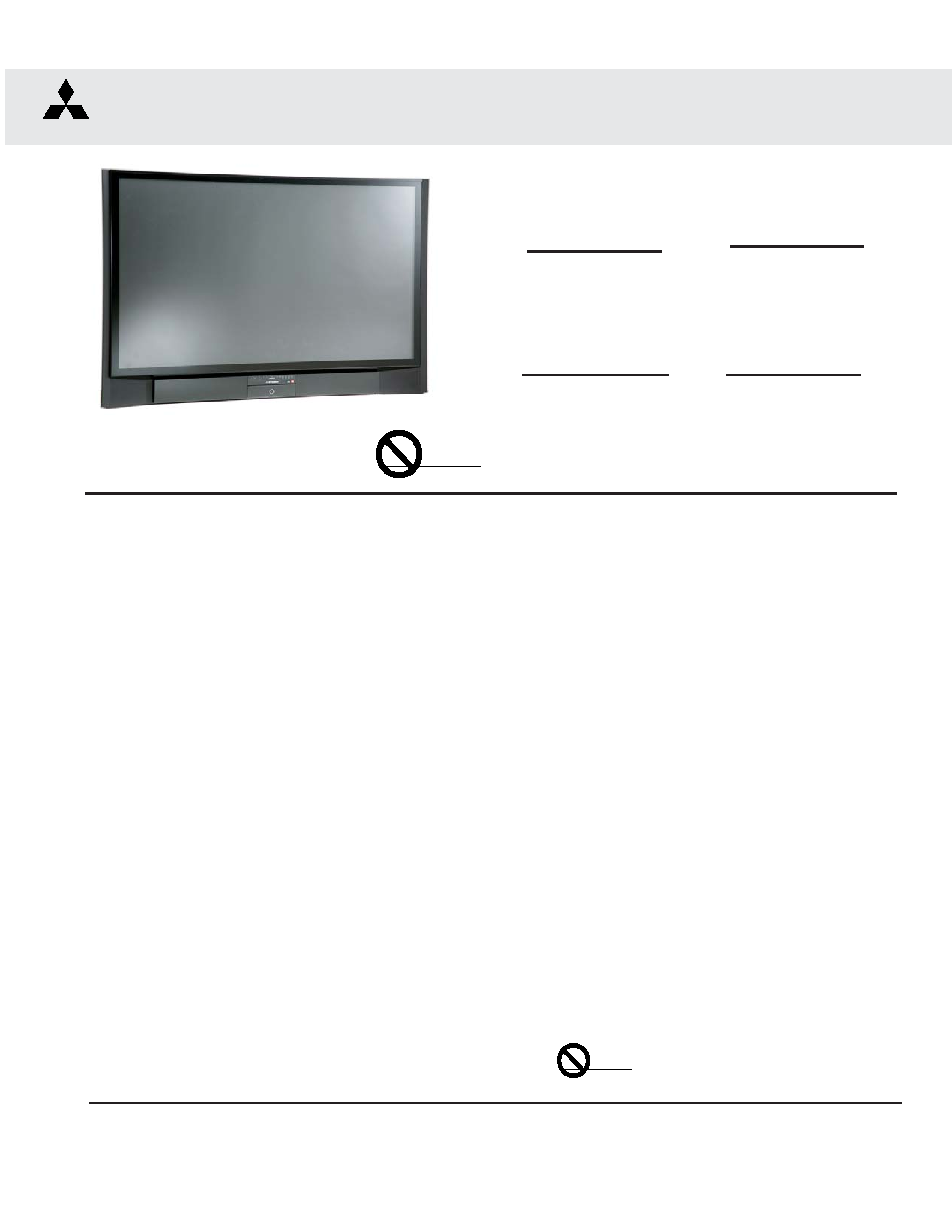
DLP PROJECTION HDTV
V29 / V30 / V30+ / V31 CHASSIS
SPECIFICATIONS
· Power Input
: AC 120V, 60Hz
· Power Usage
: See table on page 5
· Light Engine
: DLPTM (1920 x 1080 pixels)
· Light Source
: 120W [V29,V30(52"&62")]
: 150W [V30(73"),V30+,V31]
· Channel Range
: Air VHF - 2~13, UHF - 14~69
Analog Cable - 1~25
Digital Cable - 1~35
· Antenna Input
: 2 RF 75
unbalanced
· Tuning (V29,V30)
: 1 NTSC/ATSC/QAM
1 Out of Band for CableCARDTM
1 NTSC for PIP
· Tuning (V30+, V31)
: 2 NTSC/ATSC/QAM
1 Out of Band for CableCARDTM
2 NTSC for PIP
· Cabinet Dimensions
: See Table on page 5
· Weight
: See table on page 5
· Speakers (8 Ohms 10W)
: Two 1.5" Round
Two 5.5"x2.2" Oval
· Input Level
: VIDEO IN JACK (RCA Type)
1.0Vp-p 75
unbalanced
: AUDIO IN JACK (RCA Type)
-4.7dBm 43k
unbalanced
:
S-VIDEO IN JACK
(Y/C separate type)
Y:1.0 Vp-p C:0.286Vp-p(BURST)
75
unbalanced
: COMP / Y, Cr, Cb (RCA Type)
Y: 1.0 Vp-p Cr, Cb: 700mVp-p
· Output Level
: VIDEO OUT JACK (RCA Type)
1.0Vp-p 75
unbalanced
: AUDIO OUT JACK (RCA Type)
-4.7dBm 4.7k
unbalanced
· Digital
: IEEE-1394 I/O Jacks
: Digital Audio Output
(RCA Type)
: HDMITM
:
MonitorLinkTM RS-232 Control
: Memory Card Reader
: Lead-Free solder PWBs
WD-52327
V29 Chassis
WD-52627
WD-62627
V30 Chassis
WD-52628
WD-62628
WD-73727
WD-52527
Pb Solder
Pb Solder
WD-62827
V30+ Chassis
WD-62827
WD-73827
V31 Chassis
WD-62927
WD-73927


MODELS: WD-52627 / 52628 / 62627 / 62628 / 62827 / 62927 / 73727 / 73827 / 73927
Page 3
INTRODUCTION ................................................................................................................................5
Model Dimensions and Weight Specifiations ................................................................................... 5
PRODUCT SAFETY NOTICE ............................................................................................................. 5
SAFETY PRECAUTIONS ................................................................................................................. 6
DISASSEMBLY ................................................................................................................................. 7
Front Disassembly (WD-52627 / WD-52628 / WD-62627 / WD-62628 ............................................. 7
Front Disassembly (WD-62827) ...................................................................................................... 8
Front DisassembLY (WD-62927) ................................................................................................... 11
Front Disassembly (WD-73727 / WD-73827) ................................................................................. 15
Front Disassembly (WD-73927) ....................................................................................................17
Rear Disassembly ........................................................................................................................ 19
Chassis Disassembly & Accessing PWBs ................................................................................... 20
Out of Cabinet Chassis Operation ................................................................................................. 26
52" & 62" Models Optical Engine Replacement ............................................................................. 29
73" Models Optical Engine Replacement ...................................................................................... 34
DIAMOND SHIELDTM Removal ........................................................................................................ 38
SERVICING THE LENTICULAR LENS AND FRESNEL SCREEN ..................................................... 39
Removal of the Lenticular Screen and Fresnel Lens ...................................................................... 39
Installation of the Lenticular Screen and Fresnel Lens ................................................................... 40
ADJUSTMENTS ............................................................................................................................... 41
Option Menu & Defaults ................................................................................................................ 41
LED Indicator Diagnostics ............................................................................................................. 42
Error Codes Operational Check ..................................................................................................... 43
Remote Operational Mode ............................................................................................................ 44
Service Adjustment Mode ............................................................................................................. 44
Service Adjustment Mode Operation .................................................................................... 44
Resetting Data to factory values and Transferring data ......................................................... 45
Optical Engine Adjustment ............................................................................................................ 46
Test Signal activation ........................................................................................................... 46
Preliminary ................................................................................................................................... 46
Accessing Mechanical Adjustments ............................................................................................. 47
Models WD-52627 / 62627 / 52628 / 62628 ......................................................................... 47
Models WD-63827 & WD-62927 .......................................................................................... 48
Models WD-73727 / 73827 &WD-73927 ............................................................................... 49
Locking Screws & Wedge Removal .............................................................................................. 50
Rotation Adjustmentt ........................................................................................................... 51
Keystone Distortion Adjustment ........................................................................................... 51
After Adjustment .................................................................................................................. 51
Hortizontal & Vertical Position .............................................................................................. 51
USING LEAD FREE SOLDER .......................................................................................................... 52
CHIP PARTS REPLACEMENT ......................................................................................................... 53
REPLACEMENT PARTS .................................................................................................................. 54
Parts Ordering .............................................................................................................................. 54
Critical and Warranty Parts Designation ........................................................................................ 54
Parts Tolerance Codes .................................................................................................................. 54
Quick Reference List .................................................................................................................... 55
CONTENTS

MODELS: WD-52627 / 52628 / 62627 / 62628 / 62827 / 62927 / 73727 / 73827 / 73927
Page 4
SERVICE PARTS LIST .................................................................................................................... 56
SCREEN ASSEMBLY PARTS LIST .................................................................................................. 67
WD-52627 / WD-52628 / WD-62627 / WD-62628 .......................................................................... 67
WD-62827 / WD-62927 ................................................................................................................. 68
WD-73727 / WD-73827 / WD-73927 ............................................................................................. 69
CIRCUITRY BLOCK DIAGRAMS ..................................................................................................... 71
Main Power Supply ....................................................................................................................... 71
Lamp Ballast DC Supply ............................................................................................................... 72
Fans Power Supply ....................................................................................................................... 72
Optical Engine Power Supply ........................................................................................................ 73
HDD Power Supply ((V30+ & V31 Only) ........................................................................................ 73
Analog Video Signal Path ............................................................................................................. 74
Digital Video Signal Path .............................................................................................................. 75
HDD Record Signal Path ............................................................................................................... 76
Sound Signal Path ........................................................................................................................ 77
Command Input Circuitry ............................................................................................................... 78
Serial Data Control Lines .............................................................................................................. 78
Lamp Control Circuitry .................................................................................................................. 79
Lamp, Engine and Fan's Protect circuitry ..................................................................................... 80
TV Guide On screen® ................................................................................................................... 80
SCHEMATIC DIAGRAMS .....................................................................................................................
PCB LAYOUT DIAGRAMS ...................................................................................................................

MODELS: WD-52627 / 52628 / 62627 / 62628 / 62827 / 62927 / 73727 / 73827 / 73927
Page 5
This service manual includes:
1. Assembly and disassembly instructions for the front and rear cabinet components.
2. Servicing of the Lenticular Screen and Fresnel Lens.
3. Servicing down to major components, chassis, PWBs, Light Engine, Lamp Ballast, etc..
4. Electrical adjustments.
5. Optical Adjustments.
6. Lead Free Soldering.
7. Chip parts replacement procedures.
8. Simplified circuit path diagrams.
The parts list section of this service manual includes:
1. Cabinet and screen parts.
2. Electrical parts.
Block diagrams of the above listed models are included in this service manual for better understanding of the circuitry.
PRODUCT SAFETY NOTICE
Many electrical and mechanical parts in television receivers have special safety related characteristics. These charac-
teristics are often not evident from visual inspection nor can the protection afforded by them necessarily be obtained by
using replacement components rated for higher voltage, wattage, etc.
Replacement parts which have special safety characteristics are identified in this service manual.
Electrical components having such features are identified by shading on the schematic diagram and by bold type in
the parts list of this service manual. Therefore, the replacement for any safety part should be identical in value
and characteristics.
CableCARD is a trademark of Cable Television Laboratories, Inc.
TV Guide On Screen is a registered trademark of Gemstar Development Corp.
HDMI is a trademark of HDMI Licensing, LLC.
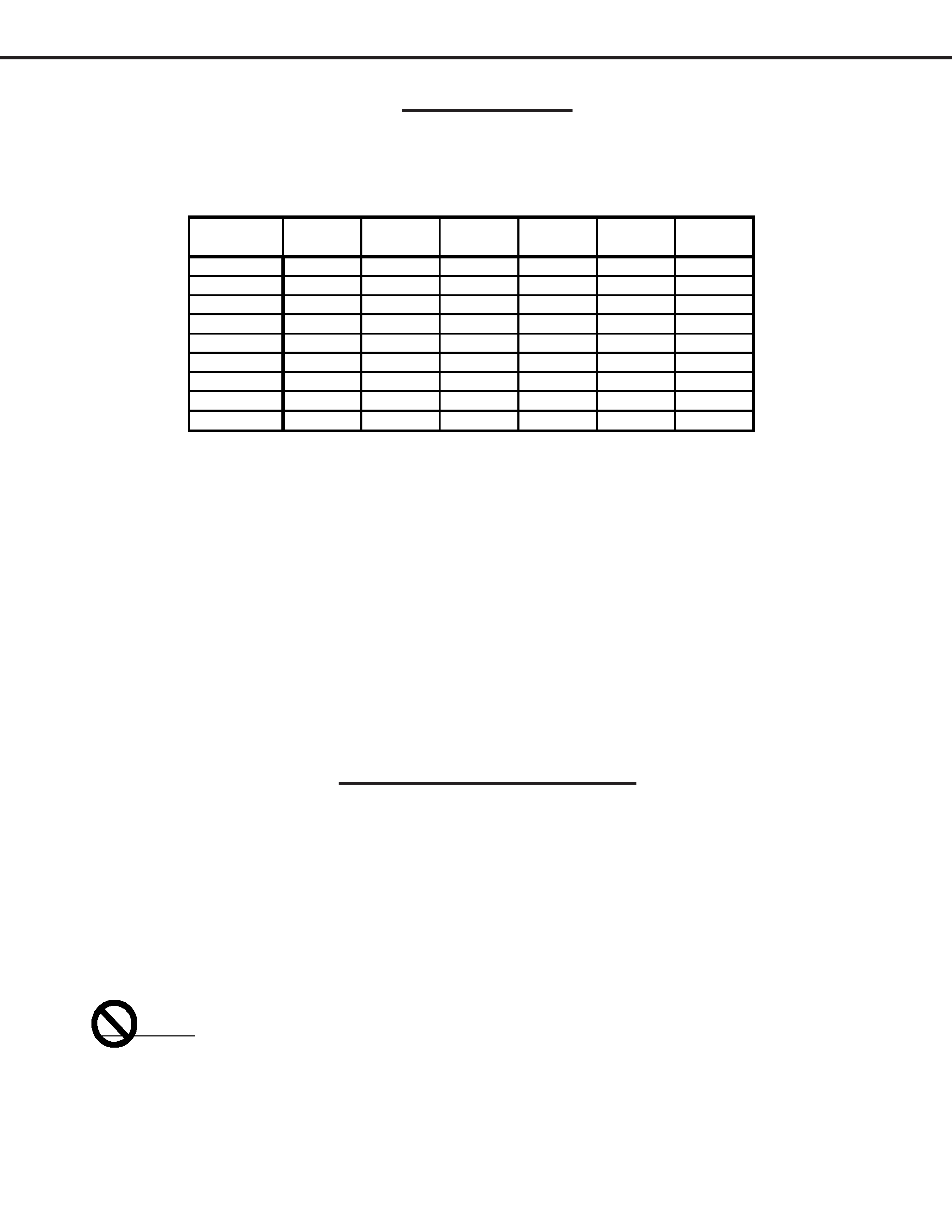
MODEL
CHASSIS
HEIGHT
WIDTH
DEPTH
WEIGHT
POWER
USAGE
WD-52627
V29
34 in.
49.6 in.
18.6 in.
121 lbs.
295W
WD-52628
V30
""
"""
WD-62627
V29
40.5 in.
58.3 in.
20.3 in
133 lbs.
"
WD-62628
V30
""
"""
WD-62827
V30+
"
60.3 in.
"
"
310W
WD-62927
V31
"
"
"
"
330W
WD-73727
V30
44.8 in.
69.9 in.
21.5 in.
165 lbs.
335W
WD-73827
V30+
"
"
"
"
350W
WD-73927
V31
"
69.8 in.
"""
Dimensions/Weight
INTRODUCTION
This service manual provides service instructions for DLP Projection TV Models and Chassis:
Pb Solder
The PWBs used in the V28 and V28+ chassis are constructed using Lead-Free solder. When
servicing use only recommended Lead-Free solder (refer to page 48).
