70%
MICRO HiFi COMPONENT SYSTEM
RD-DV5-S/DV7-L
© 2001-9 PRINTED IN KOREA
B51-5754-00 (K/K) 2345
In compliance with Federal Regulations, following are repro-
duction of labels on, or inside the product relating to laser
product safety.
KENWOOD-Corp. certifies this equipment conforms to DHHS
Regulations No.21 CFR 1040. 10, Chapter 1, subchapter J.
DANGER : Laser radiation when open and interlock defeated.
AVOID DIRECT EXPOSURE TO BEAM.
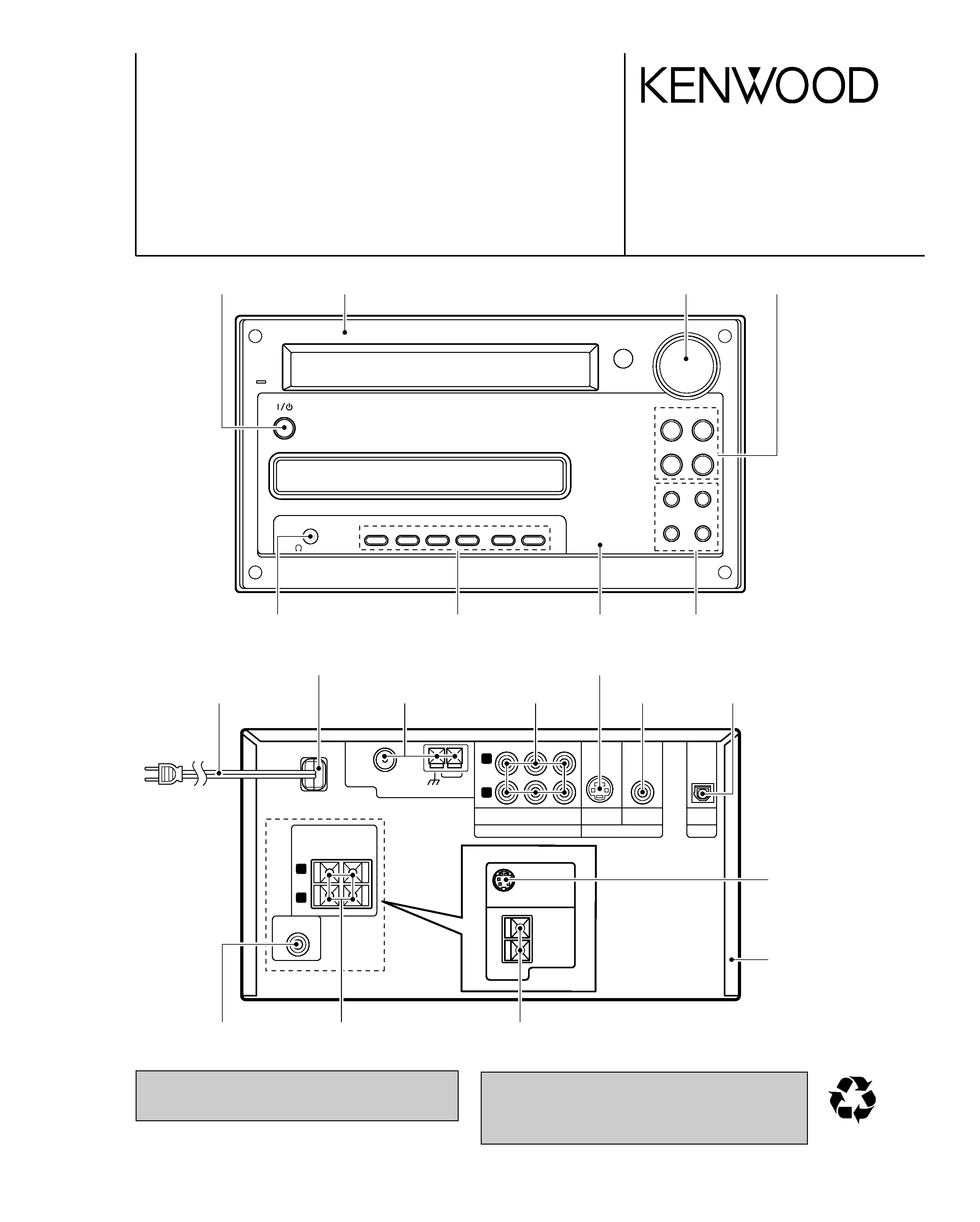
VOLUME/
MULTI CONTROL
STANDBY
/TIMER
DVD/CD
6 TUNER/BAND
4
1
¢
¡
DVD/CD
0
STOP
7
TUNING MODE
AUX
PHONES
SOUND
MODE
SET/DEMO
REPEAT
RANDOM
P.CALL
Phone jack
(E11-0941-05)
Knob
(K29-7997-03)
Knob
(K29-8001-14)
Knob
(K29-7999-03)
Panel *
(A60-)
RD-DV5MD-S
R
L
GND
FM75
AM
SUB WOOFER
PRE OUT
ANTENNA
AUDIO
AUX
IN
CD - R
OUT
S-VIDEO
VIDEO
VIDEO OUT
OPTICAL
DIGITAL OUT
PCM/BIT
STREAM
CD - R
IN
+
-
R
L
SPEAKERS
( 6 -16
)
RD-DV5
TO OPM-DV7
SATELLITE
SPEAKER
SUB
WOOFER
+
-
( 8 -16 )
RD-DV7
SERVICE MANUAL
Knob *
(K29-)
Dressing panel *
(A21-)
Knob *
(K29-)
Oscillating module
(W02-2803-05)
Pin jack *
(E63-)
AC power cord *
(E30-)
AC power cord bushing
(J42-0083-05)
Lock terminal board
(E70-0146-05)
Cylindrical receptacle
(E56-0032-05)
Tuner assy *
(W02-)
Pin jack
(E63-1220-05)
Pin jack
(E63-1162-05)
Metallic cabinet
(A01-3820-11)
Cylindrical receptacle
(E56-0038-05)
* Refer to parts list on page 48 .
Illustration is RD-DV5-S/DV7-L.
Lock terminal board
(E70-0148-05)
RD-DV5-S/DV7-L/DV5MD-S
2
CONTENTS / ACCESSORIES / CAUTIONS
CONTENTS / ACCESSORIES / CAUTIONS ............. 2
DISASSEMBLY FOR REPAIR....................................3
BLOCK DIAGRAM ......................................................6
CIRCUIT DESCRIPTION ............................................7
ADJUSTMENT ..........................................................14
WIRING DIAGRAM ...................................................15
PARTS DESCRIPTIONS ..........................................16
PC BOARD .............................................................. 17
SCHEMATIC DIAGRAM .......................................... 25
EXPLODED VIEW ....................................................45
PARTS LIST..............................................................48
SPECIFICATIONS ......................................Back cover
Contents
Accessories
The marking this product has been
classified as Class 1. It means that
there is no danger of hazardous ra-
diation outside the product.
Location: Back panel
CLASS 1
LASER PRODUCT
The marking of products using lasers (For countries other than U.S.A., U.S.-Military and Canada)
Inside this laser product, a laser di-
ode classified as Class 2 laser ra-
diation is contained as alerted by
the internal caution label shown
above. Do not stare into beam.
Location: DVD laser pick-up unit
cover inside this product
CAUTION
VISIBLE LASER RADIATION
WHEN OPEN. DO NOT
STARE INTO BEAM.
Inside this laser product, a laser di-
ode classified as Class 3B laser ra-
diation is contained as alerted by
the internal caution label shown
above. Avoid exposure to laser
beams.
Location: MD laser pick-up unit
cover inside this product
CAUTION
VISIBLE LASER
RADIATION WHEN OPEN.
AVOID EXPOSURE TO BEAM.
Operation to reset
The microcomputer may fall into malfunction (impossibility to
operate, erroneous display, etc.) when the power cord is un-
plugged while unit is ON or due to an external factor. In this
case, execute the following procedure to reset the micro-
computer and return it to normal condition.
Unplug the power cord from the power outlet
then, while holding the STOP
7 /TUNING MODE
key depressed, plug the power cord again.
÷ Please note that resetting the microcomputer clears
the contents stored in and it returns to condition
when it left the factory.
REMOTE
MODEL
MAIN UNIT
DESTINATION
CONTOROLLER
NAME
A70-1521-05
RC-M0513 RD-DV5MD-S
M
A70-1522-05
RC-F0504E
RD-DV5-S
TE
A70-1524-05
RC-F0505
RD-DV7-L
M2X2V2
A70-1525-05
RC-F0505E
RD-DV7-L
T2E2
SYSTEM
MAIN UNIT
DESTINATION SPEAKER SP CORD PARTS No.
HM-DV6MD RD-DV5MD-S
M
LS-DV6-S
E30-5500-05
HM-DV5
RD-DV5-S
TE
LS-DV5-S
E30-5941-04
HM-DV6
RD-DV5-S
E
LS-DV6-S
E30-5500-05
HM-DV7
RD-DV7-L
T2E2M2X2V2 OPM-DV7-L
E30-5943-08
Remote controller
System configurations
Cautions
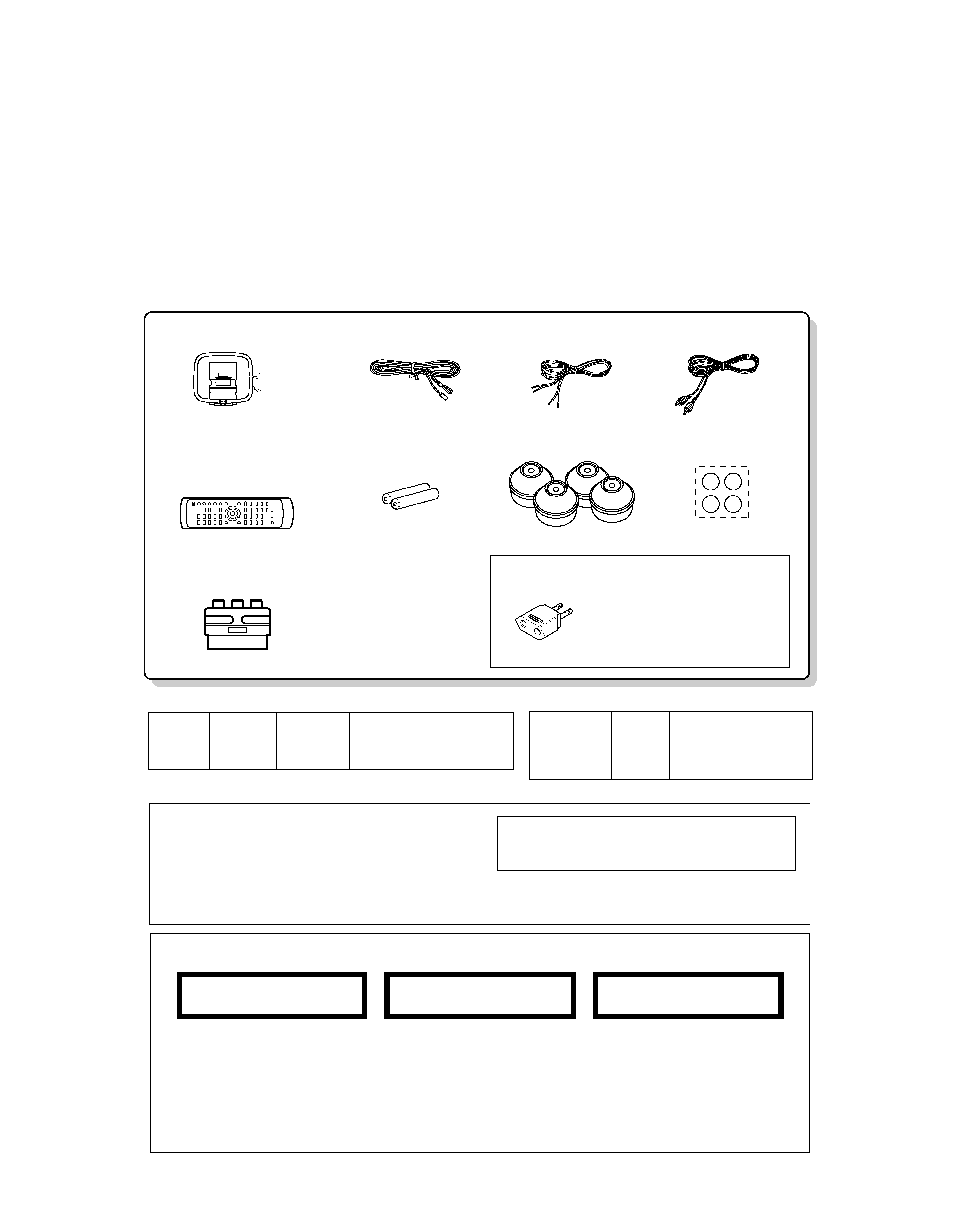
FM indoor antenna (1)
(T90-0855-05)
AM loop antenna(1)
(T90-0852-05)
Video cord(1)
(E30-7226-05)
Speaker cord(2)
Remote control unit(1)
(A70-1521-05): M
(A70-1522-05): TE
(A70-1524-05): M2X2V2
(A70-1525-05): T2E2
Batteries (R6/AA)(2)
SCAT plug adaptor for TV(1)
(For EUROPE and U.K.)
(E69-0012-05)
Cushion for satellite speaker(4)
(W01-1178-08)
Feet for speaker(4)
(J02-0034-08)
AC Plug Adaptor (1)
(E03-0115-05)
Use to adapt the plug on the
power cord to the shape of the
wall outlet.
(Accessory only for regions where
use is necessary.)
RD-DV5-S/DV7-L/DV5MD-S
3
DISASSEMBLY FOR REPAIR
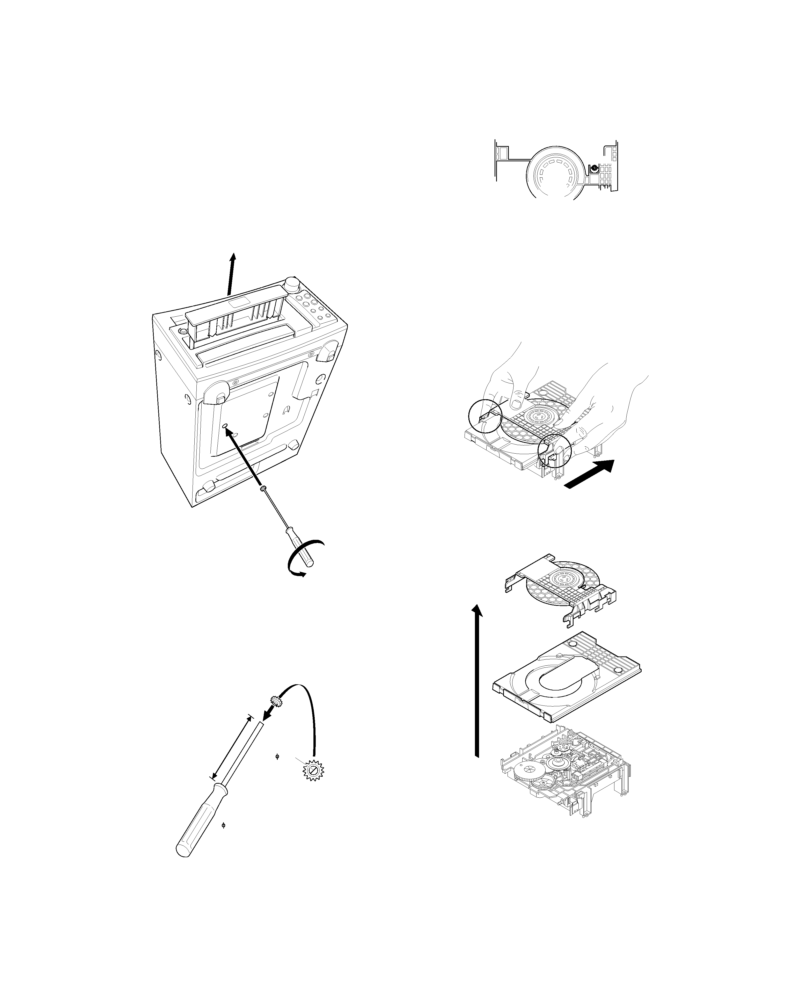
How to open the tray if it does not come out.
1. Insert a jig and turn it fully ccw in the drawing through the
hole on the loading chassis bottom.
2. Pull out the tray frontward by hand when it comes just out.
Fig .1
* How to make a jig
Insert a hex wrench to a hole of gear (W05-0881-00) in
the drawing below.
If you lost the gear use it which located on DVD mecha-
nism in the drawing (Fig .3).
Fig. 2
Fig. 3
How to open the tray and a clamper.
1. Pull out the tray slightly frontward by hand.
(Refer to Fig .1)
2. Remove the tray.
3. Remove the clamper in the arrow direction.
Fig. 4
4. Remove the tray and clamper upward.
Fig. 5
5cm
(HEX DRIVER)
2mm
2mm
GEAR
DVD(CD) MECHA
GEAR
RD-DV5-S/DV7-L/DV5MD-S
4
DISASSEMBLY FOR REPAIR
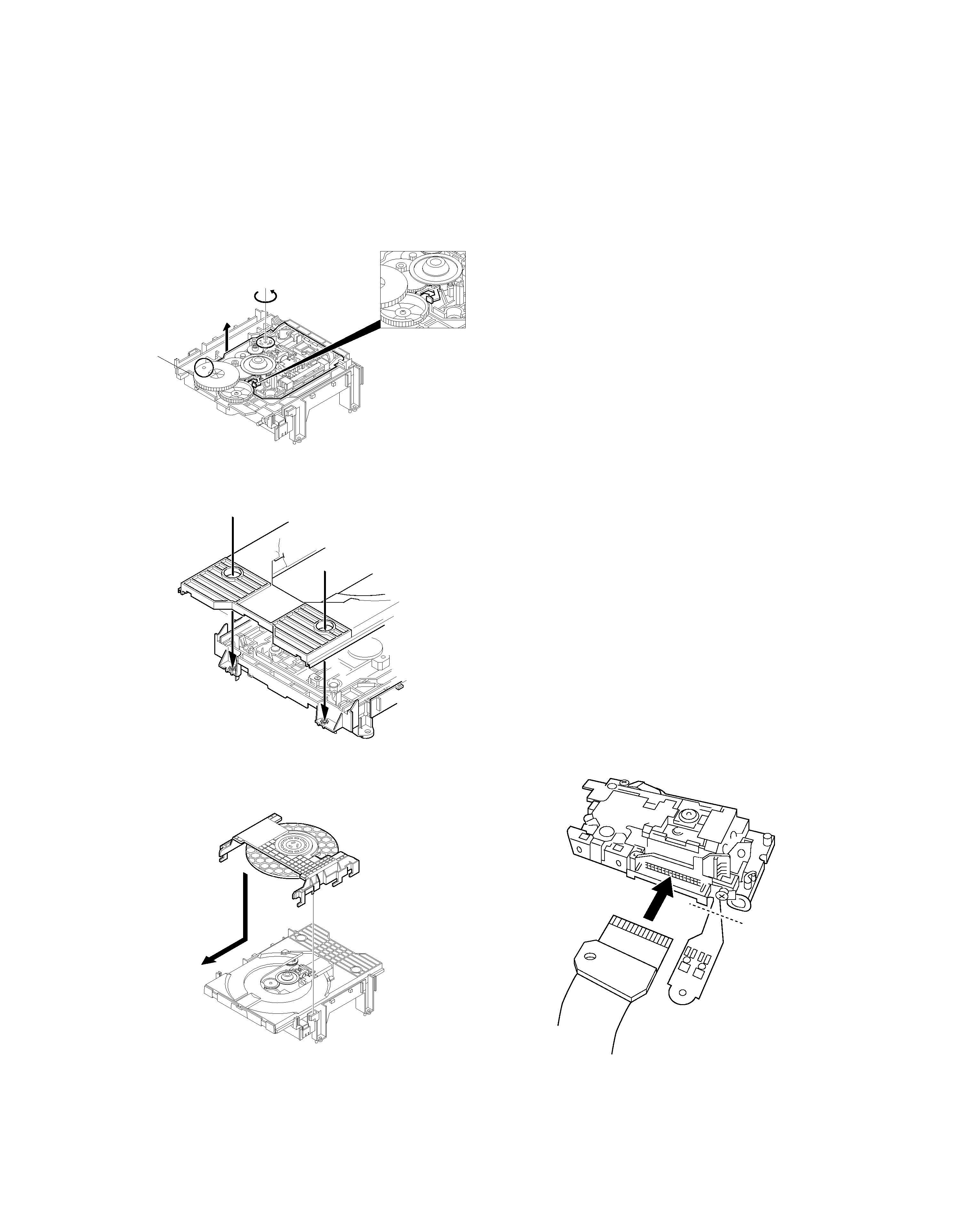
How to attach the tray and the clamper.
1. Turn the traverse gear A in the direction of the arrow in
the drawing so that the traverse
unit will reach the highest position.
Fig. 6
2. Attach the tray in the arrow direction.
Fig. 7
3. Attach the clamper in the arrow direction.
Fig. 8
Assembling and Disassembling the Opti-
cal Pickup
The optical pickup can be damaged by static electricity
from your body.
Be sure to take static electricity countermeasures when
working around the optical pickup.
Handling the Optical Pickup
1. The optical pickup is an extremely high-precision mecha-
nism. Do not subject it to strong damage.
2. Testers cannot be used to check the laser diode of the
optical pickup. The power supply in side the tester can
easily damage the laser diode.
3. Take care when handling the flexible cable because
excessive force can cause it to break.
4. To preserve the quality of the optical pickup replacement
parts during transport and installation, the terminals of the
laser diode are short-circuited. After replacing the parts,
use the proper procedure to return the laser diode to its
original condition.
Static Electricity Countermeasures
The laser diode inside the traverse unit (optical pickup )
can be damaged by static electricity from your body. Be
sure to take static electricity countermeasures when work-
ing around the optical pickup.
Static Electricity Countermeasure Methods
1. Ground yourself
Use an anti-static wrist strap to discharge static electricity
from your body.
2. Ground the workbench
Lay a conductive material (sheet) or steel sheet on the
surface where the traverse unit (optical pickup)is to be
placed, then ground the sheet.
Assembling the Optical Pickup
1. Insert a flexible cable in the arrow direction in the drawing.
2. Cut the flexible cable.
TRAVERSE
GEAR A
GEAR B
CUT
MECHA.
CHASSIS
PUSH RIVETS
HOOKS
MIDDLE CHASSIS
GUIDE SHAFT
DRIVE SHFT
SCREW
SCREW
SCREW
SPRING HOLDER
OPTICAL PICKUP
SPRING HOLDER
SPRING HOLDER
RD-DV5-S/DV7-L/DV5MD-S
5
DISASSEMBLY FOR REPAIR
Disassembling the Optical Pickup
1. Remove screws.
2. Remove spring holder and spring.
3. Pull out the drive-shaft and guide shaft.
Disassembling the Middle Chassis
1. Remove 3 push rivets.
2. Remove the hooks.
3. Lift the traverse unit upward to remove the middle chassis.
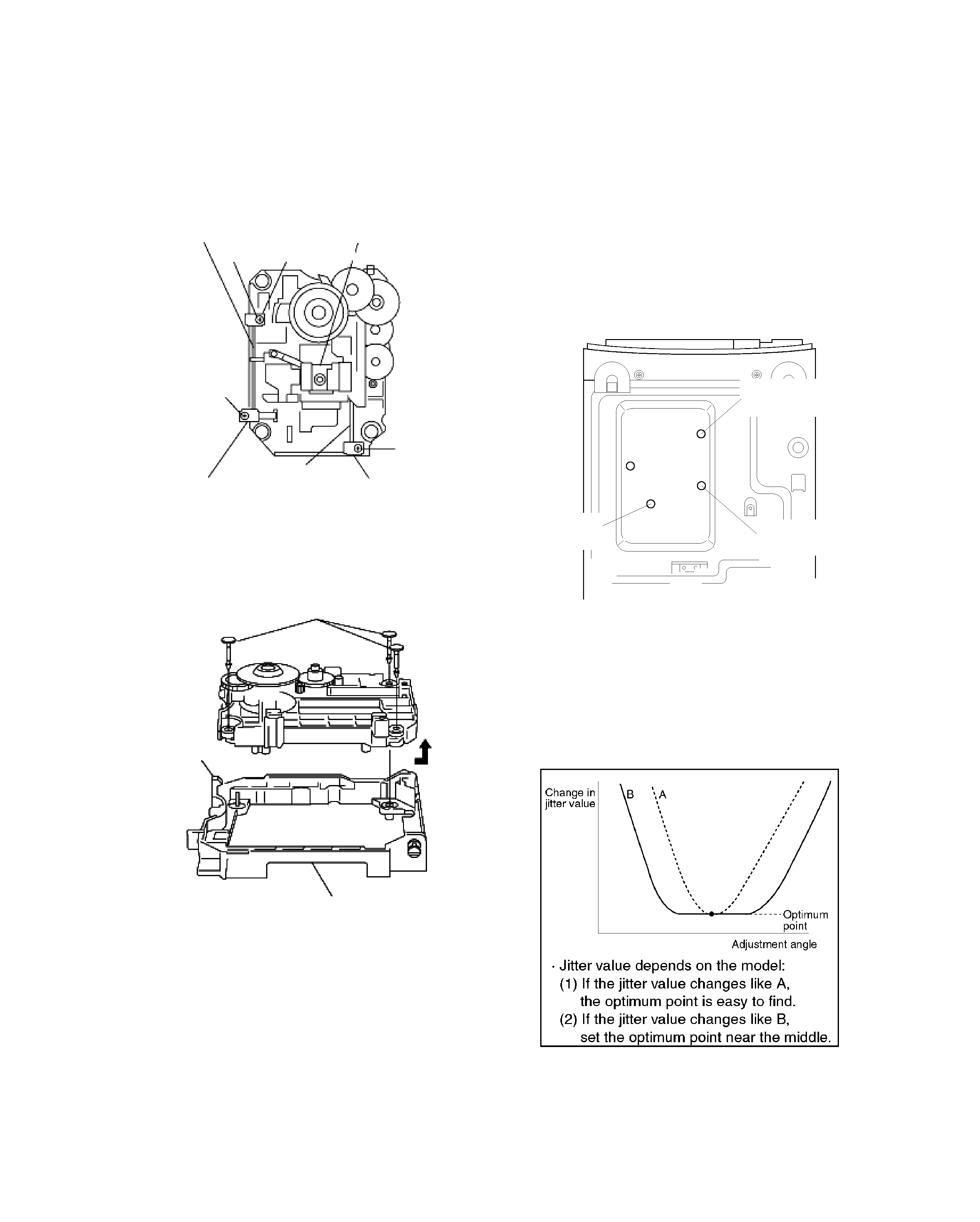
1. Optical pickup Tilt Adjustment
1-1 Adjustment
1. Insert the AC power plug to AC wall outlet with press-
ing the DVD/CD play key.
(The tray opens automatically)
2. Load a DVD disc and press DVD/CD play key.
3. Press "SOUND" key.
(Jitter value is displayed.)
JITT XXX %
XXX is present jitter value
*4. Play DVD disc first chapter (inner periphery).
5. Adjust to the minimum jitter value.
(Tangential adjustment screw)
*6. Play DVD disc last chapter (outer periphery).
7. Adjust to the minimum jitter value.
(Tilt adjustment screw1)
*8. Play DVD disc last chapter (outer periphery).
9. Adjust to the minimum jitter value.
(Tilt adjustment screw2)
10. Repeat adjusting tilt adjustment screws 1 and 2 alter-
nately, two or three times.
* Press "SKIP UP/SKIP DOWN" keys for Tno. up or
down.
Do item 5~10 from the bottom of the main unit using a
hex wrench.
1-2 Point
1. First of all adjust tangential adjustment then adjust tilt
adjustment.
2. To get optimum point, repeat item 1 adjustment alter-
nately, two or three times.
3. Finally, adjust the tilt adjustment.
1-3 Check condition after adjustment
1. Play the disc to make sure there is no picture degrada-
tion in the inner, middle and outer peripheries, and no
audio skipping.
2. Lock the adjustment screw in position using screw lock.
TILT ADJ.
SCREW 1
BOTTOM VIEW
TILT ADJ.
SCREW 2
TANGENTIAL
ADJ.SCREW
FRONT
