© 2004-2 PRINTED IN JAPAN
B53-0139-00 (N) 2439
POWER AMPLIFIER
KAC-PS521
KAC-X521
SERVICE MANUAL
01
2
3
4 5 6 7
8
9
RESET
REMOTE
TO H/U
ID NUMBER
POWER IN
30
30
FUSE(30A
×2)
VOLT
FAN
CURR
TEMP
MENU
Screw set
(N99-1752-05)
Screw set
(N99-1577-15)
Heat sink
(F01-1751-01)
Accessory
(W01-1606-05)
Cover
(F07-1138-12): KAC-X521
(F07-1139-12): KAC-PS521
Screw
(N07-0003-08)
Screw
(N09-4214-08)
Fuse (30A)
(F52-0015-05)

KAC-PS521/X521
2
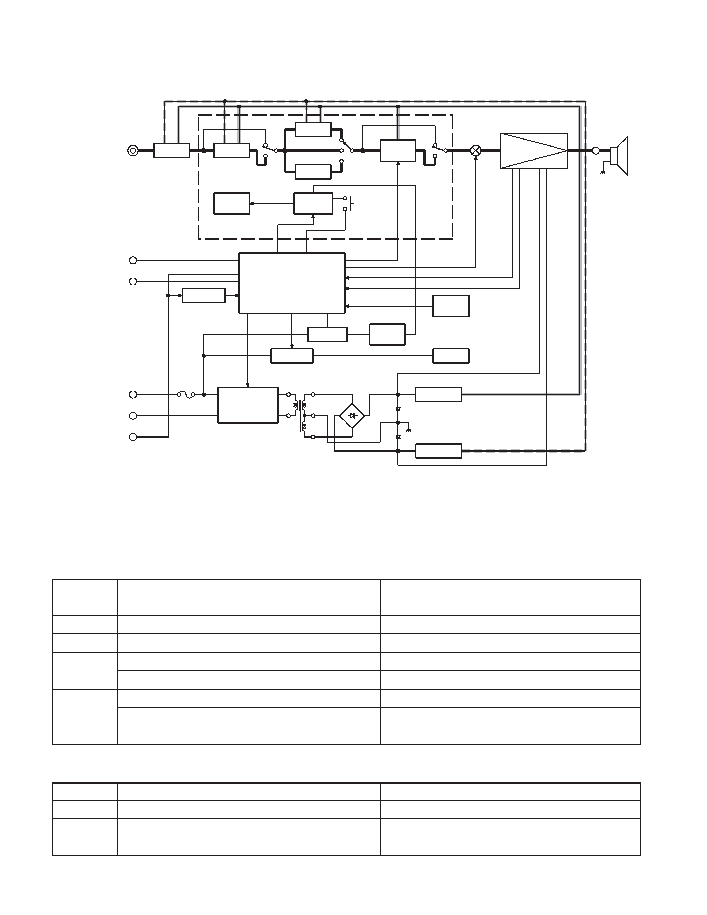
BLOCK DIAGRAM
(X09-5760-10)
(X08-4150-10)
I.S.A
I.F.S
L.P.F
H.P.F
LCD
DRIVER
LCD
V PROT.
TEMP
PROT.
IC1,10
IC1
IC3,4,6
IC5
ED1
IC7
MUTE
POWER AMP
Q101,102
CONT.
AMP
u-COM
5V AVR
FAN AVR
FAN
-15V AVR
+15V AVR
DC/DC
CONVERTER
SW 5V
AVR
Q69
Q66
Q356,358
IC2
Q61
Q62
IC6
P-CONT
GND
BAT
to POWER AMP
to H/U
CURRENT PROT
DC PROT
PREAMPLIFIER UNIT (X08-4150-10)
Ref. No
Application / Function
Operation / Condition / Compatibility
IC1
Infrasonic filter
Controlled by microprocessor
IC3
Tone and volume variable
IC4
6dB voltage amplification
IC5
HPF
LPF
IC6
Lch : 6dB voltage amplification
Rch : Signal 180 reverse and 6dB voltage amplification
IC7
LCD driver
Controlled by microprocessor
AUDIO UNIT (X09-5760-10)
Ref. No
Application / Function
Operation / Condition / Compatibility
IC1
Buffer
IC2
DC/DC converter
IC3
AMP communication buffer
COMPONENTS DESCRIPTION

KAC-PS521/X521
3
Ref. No
Application / Function
Operation / Condition / Compatibility
IC5
H/U communication buffer
IC6
Microprocessor
IC7
Reset IC
IC8
E2PROM
IC9
Current detection
IC10
Isolation amplifier
Q50
5V AVR
Q51~54
DC/DC output driver
Q55~60
DC/DC
Q61
+15V AVR
Q62,63
-15V AVR
Q64,65
DC/DC converter (IC2) ON/OFF
Controlled by microprocessor
Q66,68
5V AVR
Q69
5V AVR ON/OFF
Q70,71
Power supply detection
Q81
+15V AVR
Q91,92
When P-CON is OFF, DC/DC driver stop speedy
Q97
AMP communication stability power supply
Q101,102
Mute
Q103~112
A class first stage amplifier
Q113~118
A class 2nd stage amplifier
Q119,120
Final temperature compensation
Q121~124
Amplifier current detection
Q125~132
Final driver
Q133~140
Final
Q141
Mute control
Q142~145
Amplifier limiter
Q146,147
Amplifier current detection
Q148,149
DC detection
Q301~307
H/U communication output driver
Q313
H/U communication output driver
Q314
H/U communication ON/OFF
Q341~344
H/U communication input driver
Q346
H/U communication output driver
Q347~349
AMP and H/U communication ON/OFF control
Q351,352
BATT voltage output
Q353~358
Fan stability power supply
Q403
LCD backlight LED control
Q404
LED control
COMPONENTS DESCRIPTION

KAC-PS521/X521
4
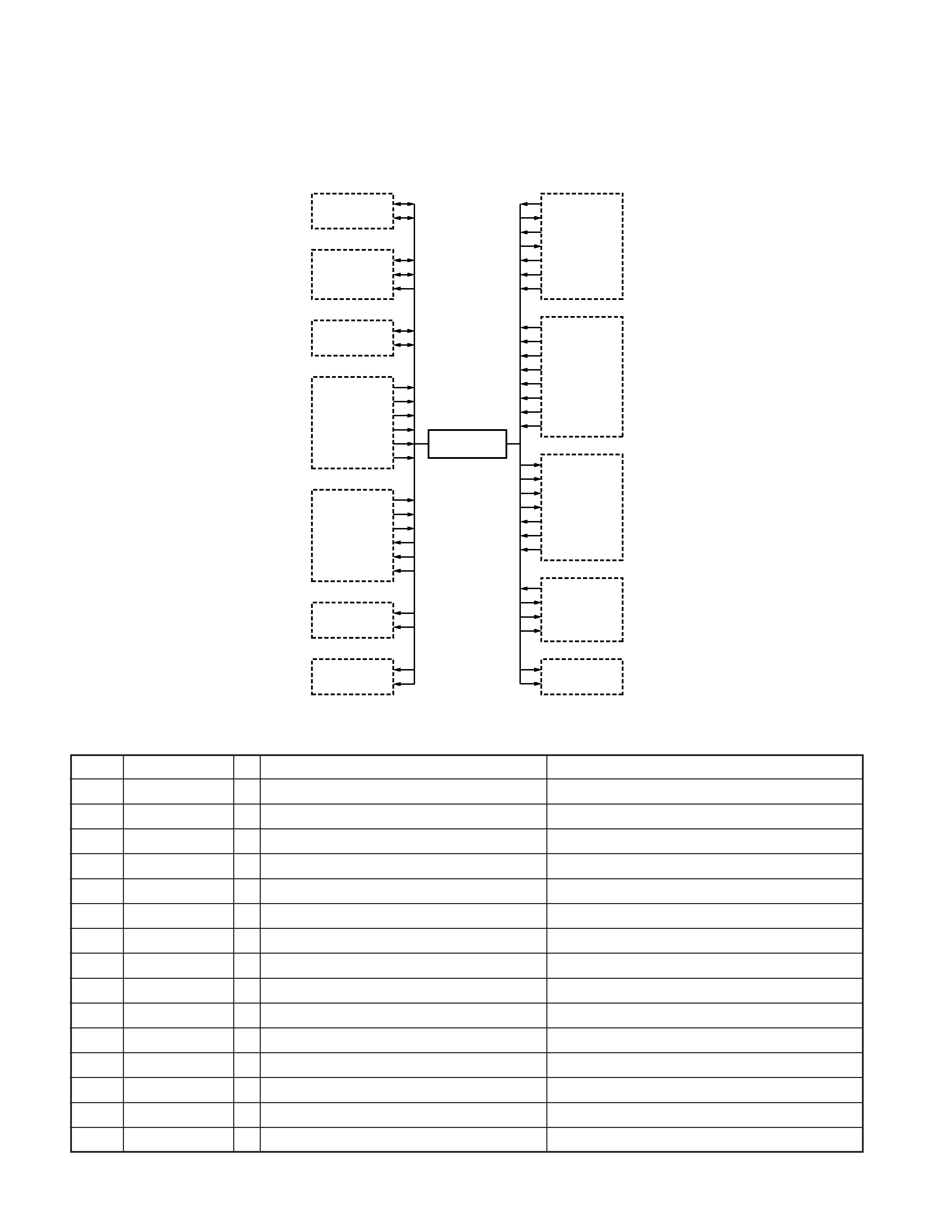
AMP_SCL
LX_REQ_M
LX_REQ_S
LX_DATA_M
LX_DATA_S
LX_CLK
LX_RST
HU_BU
AD-I
AD-V
TEMP1
TEMP2
TEMP3
TEMP4
TEMP5
TEMP6
COMM-SW
D-PWER
POWER-ON
5VSW
V_DOWN
PCON
LX_CON
L_DATA_L
L_DATA_A
L_CLK
L_CE
FAN1
FAN2
AMP_SDA
AUDIO_SCL
AUDIO_SDA
AUDIO_MUTE
E2P_SCL
E2P_SDA
LCD-ILL
WHITE-LED
MUTE1
MUTE2
DIP-SW1
DIP-SW2
DIP-SW3
DIP-SW4
MODEL1
MODEL2
DC-DET
D-CUR
AB-CUR
ATT1
ATT2
ATT3
AMP
µ-com
784224YGC117
Audio control
AMP communication I/F
LX BUS I/F
Display data monitor
Power supply control
LCD driver I/F
Fan control
Destination, AMP ID
Protection control
Illumination control
Mute control
E2PROM I2C
communication
MICROPROCESSOR : 784224YGC117 (X09 : IC6)
Block Digram
Terminal Function
Pin No.
Pin Name
I/O
Function
Processing Operation Description
1~3
TEMP4~TEMP6
I
Temperature detection 4~6
4AVSS
-
GND
5
L_CE
O
CE output to LCD driver
H : LCD driver CE
6
LX_REQ_S
O
Data transmit request to H/U
H : OFF, L : ON
7AVREF1
-
DA reference voltage
8
L_DATA_L
I
Data input from LCD driver
9
L_DATA_A
O
Data output to LCD driver
10
L_CLK
O
CLK output to LCD driver
11
LX_DATA_M
I
Data input from H/U
12
LX_DATA_S
O
Data output to H/U
13
LX_CLK
I
CLK input from H/U
14
LX_BU
I
LX BUS communication, H/U connect detection
H : Not connect (Except master amplifier), L : Connect
15
NC
O
Not used
16
SDA_AMP
I/O
Data input/output AMP communication
17
NC
O
Not used
MICROCOMPUTER'S TERMINAL DESCRIPTION

KAC-PS521/X521
5
Pin No.
Pin Name
I/O
Function
Processing Operation Description
18
SCL_AMP
I/O
CLK input/output AMP communication
19
AUDIO_SCL
I/O
CLK input/output with audio chip
20
AUDIO_SDA
I/O
Data input/output with audio chip
21
AUDIO_MUTE
O
Mute output to audio chip
H : Mute OFF, L : Mute ON
22
E2P_SCL
I/O
CLK input/output with E2PROM
23
E2P_SDA
I/O
Data input/output with E2PROM
24
NC
O
Not used
25~28
DIP-SW1~DIP-SW4
I
AMP address setting
29
MODEL1
I
Model setting 1
30
MODEL2
I
Model setting 2
31,32
NC
O
Not used
33
VSS1
-
GND
34~37
NC
O
Not used
38
LCD-ILL
O
LCD backlight switch
H : ON, L : OFF
39
WHITE-LED
O
Triangle illumination switch
H : ON, L : OFF
40
NC
O
Not used
41~43
ATT1~ATT3
O
Output attenuate due to rise in temperature 1~3
H : Attenuate, L : Not attenuate
44,45
NC
O
Not used
46
COMM-SW
O
Communication IC power switch
H : ON, L : OFF
47~50
NC
O
Not used
51
D-PWER
O
D class amplifier power supply control
H : ON, L : OFF (2ch/4ch L fixed)
52
DC-DET
I
Speaker output DC voltage detection
H : Normal, L : Abnormal
53
NC
O
Not used
54
POWER-ON
O
Amplifier power supply control
H : ON (D/AB class), L : OFF
55
5VSW
O
5VSW
H : OFF, L : ON
56
MUTE1
O
Amplifier section input stage mute control
H : OFF, L : ON
57
MUTE2
O
Driver stage pop-noise mute control
H : OFF, L : ON
58
FAN1
O
Fan rotation control
H : Operate, L : Stop
59
FAN2
O
Fan speed control
H : Low speed, L : High speed
60
RESET
-
Hard reset
H : Normal, L : Reset
61
PCON
I
Amplifier power control
H : OFF, L : ON
62
LX_CON
I
LX-BUS communication control
H : OFF, L : ON
63
LX_REQ_M
I
Data receive request from H/U
H : ON, L : OFF
64
NC
O
Not used
65
V_DOWN
I
Momentary power down detection
H : ON (Power down detection), L : OFF (L fixed)
66
NC
O
Not used
67
VSS0
-
GND
68
VD1
-
VDD
69
X2
-
Main clock input 1
70
X1
-
Main clock input 2
MICROCOMPUTER'S TERMINAL DESCRIPTION
