SERVICE MANUAL
No.20836B
XV-521BK/523GD
XV-525BK/421BK
XV-521BK/523GD
XV-525BK/421BK
VICTOR COMPANY OF JAPAN, LIMITED
OPTICAL DISC BUSINESS DIV. PERSONAL & MOBILE NETWORK BUSINESS UNIT
AV & MULTIMEDIA COMPANY 1644, Shimotsuruma, Yamato, Kanagawa 242-8514, Japan
DVD PLAYER
No.20836B
July. 2000
Printed in Japan
200007 (S)
XV-521BK/523GD
XV-525BK/421BK
J
U.S.A
Area Suffix
XV-525BK/523GD
J
U.S.A
C
Canada
Area Suffix
XV-521BK
Area Suffix
XV-421BK
Supplement
The following are the altered sections on the previously issued [XV-521BK/523GD/525BK/421BK]
No.20836.
1. "Main adjustment" are added.
2. "Check point for each error" are added.
3. IC701 (M101C12GHA) is added on "Description of major ICs" section.
COPYRIGHT
2000 VICTOR COMPANY OF JAPAN, LTD.

1-2
XV-521BK/523GD/525BK/421BK
(1) Auto adjustment method
If microprocessor (IC401, IC402, IC791, IC403) or Pick-up is replaced, initialize
the DVD player in the following matter:
1. Initialize the DVD player in the following matter:
1) Make sure that no disc is on the tray.
2)Insert the power pulag to the outret while pressing "PLAY" and "OPEN/CLOSE" button at the
same time.
FL Display indicate "TEST
"
(
;Version.
3)Press 3D-PHONIC button. And EEPROM initialize start.
4)When indicate "V.REPLACE" on the display , initialize finished.
Adjustment and confirmation matter
Main adjustment
;Region code)
The test mode is cancelled when the power is turned off.
1) Make sure that no disc is on the tray.
2)Insert the power pulag to the outret while pressing "PLAY" and "OPEN/CLOSE" button at the
same time.
3)Press the "OPEN/CLOSE" button to move the tray outward.
Put the Test Disc (VT-501)on the tray and press "OPEN/CLOSE" button.
The tray should move inward (Note:Don't push to close the tray directly by hand etc.
4)Press the "PLAY" button.
5)The laser current and the jitter value is displayed on the FL indicator as follows.
6)Set the Jitter value of FL indicator to minimum by adjusting the pick-up guide shaft flap.
(2)Flap adjustment of the Pick-up guide shaft
FL Display indicate "TEST
"
(
;Version.
;Region code)
39
0
0
0
0
4
d
Laser current value
Jitter value
FL indicator
The test mode is cancelled when the power is turned off.

1-3
XV-521BK/523GD/525BK/421BK
Measurement
Adjustment point
Refer to Fig.2
Mode
Reproduction
part
Disc
Measurement machine
No need
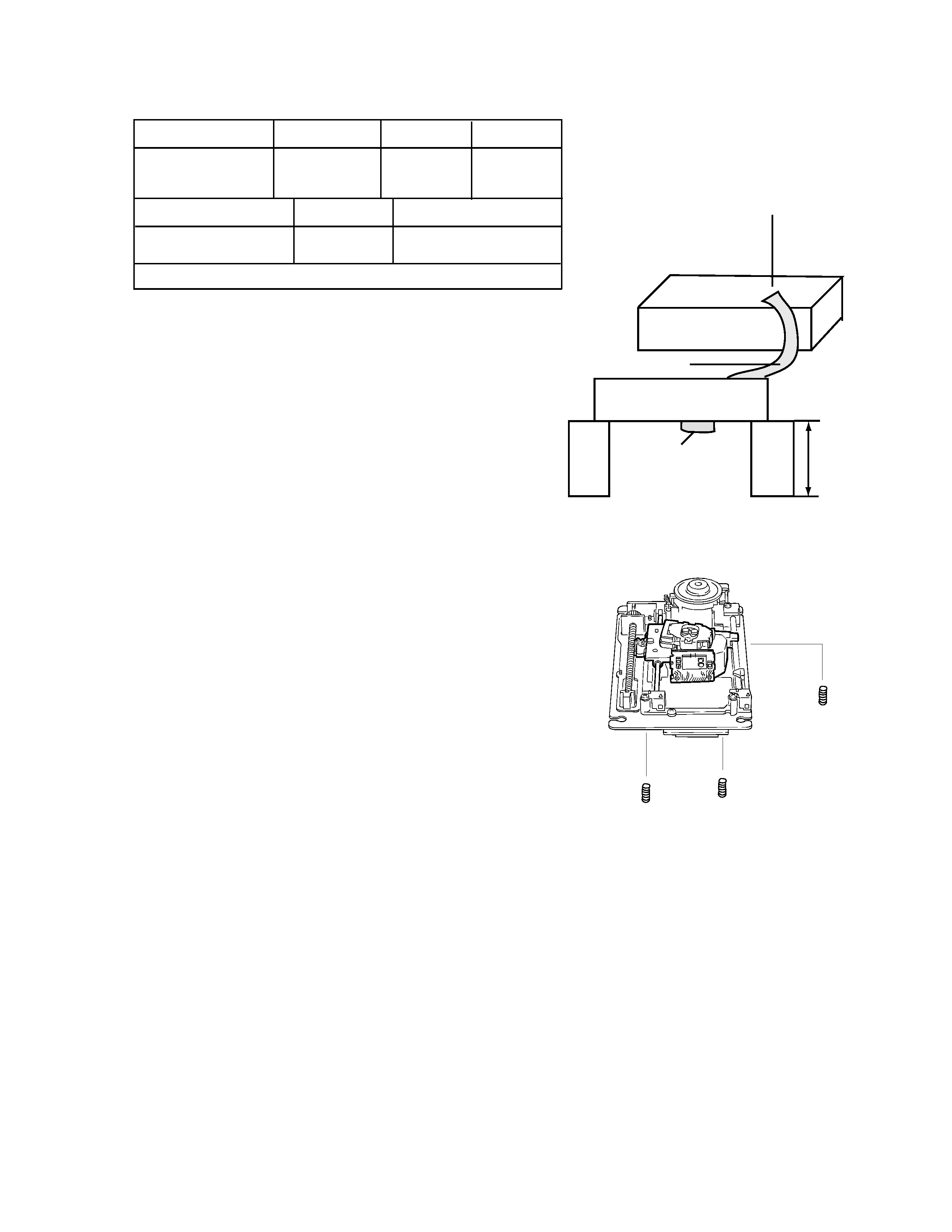
"Flap adjustment" of the Pick-up guide shaft adjusts
"Tangential adjustment machine screw" A and
"Tilt adjustment machine screw" B from the
DVD Mechanism A'ssy bottom.
1. The part at the center on the DVD test disc is
reproduced.
2.The flap adjustment screws is turned alternately
and set the jitter value of FL indicator to its minimum.
Note
1.The tangential adjustment is done finish and,
then, tilt is adjusted.
2.The repeat the adjustment 2-3 times,for best
result.
3.The final adjustment should be tilt adjustment.
VT-501
DVD Mechanism A'ssy
Stand
Stand
200mm
Fig.1
CN101 of DVD Servo Control PWB
CN101 of
Connection PWB
Extension Cord
connections
Refer to Fig.1
Extension cord No.
General tool : Hex-head wrench(1.27mm)
Flap adjustment method
DVD Player
FL Display
Confirmation after adjustment.
Confirm to reproduce video CD and CD after
the DVD test disc is adjusted and to find abnormality.
(3) About keeping the disc
As for the DVD test disc, plane accuracy is demanded.Please note the keeping place on the disc.
1. Please do not put the disc directly on the work desk etc. after uses .
2.To keep the planarity of the disc, politely handle ,and please put in a special case and keep
the disc vertically after uses .
Please keep keeping the disc in a cool place where direct sunshine and the air-conditioning
wind do not drive.
3.When the disc curves,an accurate adjustment cannot be done.
Please exchange for a new test disc and adjust optics.
4 Other discs might not be able to be reproduced when adjusting on a curved disc.
A
B
Fig.2
B
QUQ605-4040AJ

1-4
XV-521BK/523GD/525BK/421BK
Point of adjustment
* Please execute the static electricity protection measures before starting the
adjustment.
* When the following parts are exchanged,optical adjustment "Adjust the flap of Pick-up guide
shaft" is necessary.
1.The disc motor was exchanged.
2.The laser pick up was exchanged.
3.The traverse motor unit was exchanged.
Note
Additionally, please adjust the flap of the disc motor when the picture quality deterioration is
seen .The basic adjustment though, is unnecessary for part exchange in the traverse.
An optical adjustment in the laser pick up cannot be done.
Please adjust the flap of the disc motor after exchanging the laser pick up.
* When the traverse unit is exchanged, the adjustment is basically unnecessary.

1-5
XV-521BK/523GD/525BK/421BK
Checkpoints for individual errors
(1) Spindle startup error
(3) Traverse movement error
(2) Disk detection, distinction error (no discs, no REFNV)
1. Defective spindle motor
* Is the resistance between CN101 "34-35" and "36-37" about 10 to 6 ohms? (Measure it with the power OFF.)
* Is the voltage waveform for the hall element CN101"40" square-wave? (During rotation)
2. Defective spindle driver (IC271)
* Is DC voltage applied to IC271"14-15"?
* Is IC271"25" set to "H" (SPMUTE)?
3. Servo IC
Is control available at the motor driver?
* IC201"52"
R290 50% duty during stop. Variable during rotation (Fluctuates especially during startup.)
If no control available: pattern servo IC, IC201.
4. Is FG input in the servo IC?
* IC271"42"
IC271"41" 0275 IC201"53" (FG) FG waveform observation
If no FG input: pattern IC271, IC201.
1. Defective traverse motor
* Is voltage applied between CN101 "38" and "39"?
2. Defective BTL driver
* Is voltage applied on IC271 "9" and "10"?
* Is MUTE1 terminal "26" of IC271 set to "H"?
* Is drive voltage applied to servo IC201"51"?
Defective servo IC or defective pattern
1. Defective laser
2. Defective front-end processor (IC101)
3. Defective APC circuit
Q101, Q102
4. Defective pattern
A pattern between all CN101 PIC related patterns and the IC101
5. Defective servo IC (IC201)
6. IC101
Are IC101"20"(AS), IC101"41"(RFENV), and IC101"22"(FE) included in the signal to IC201?
