FUNC 1
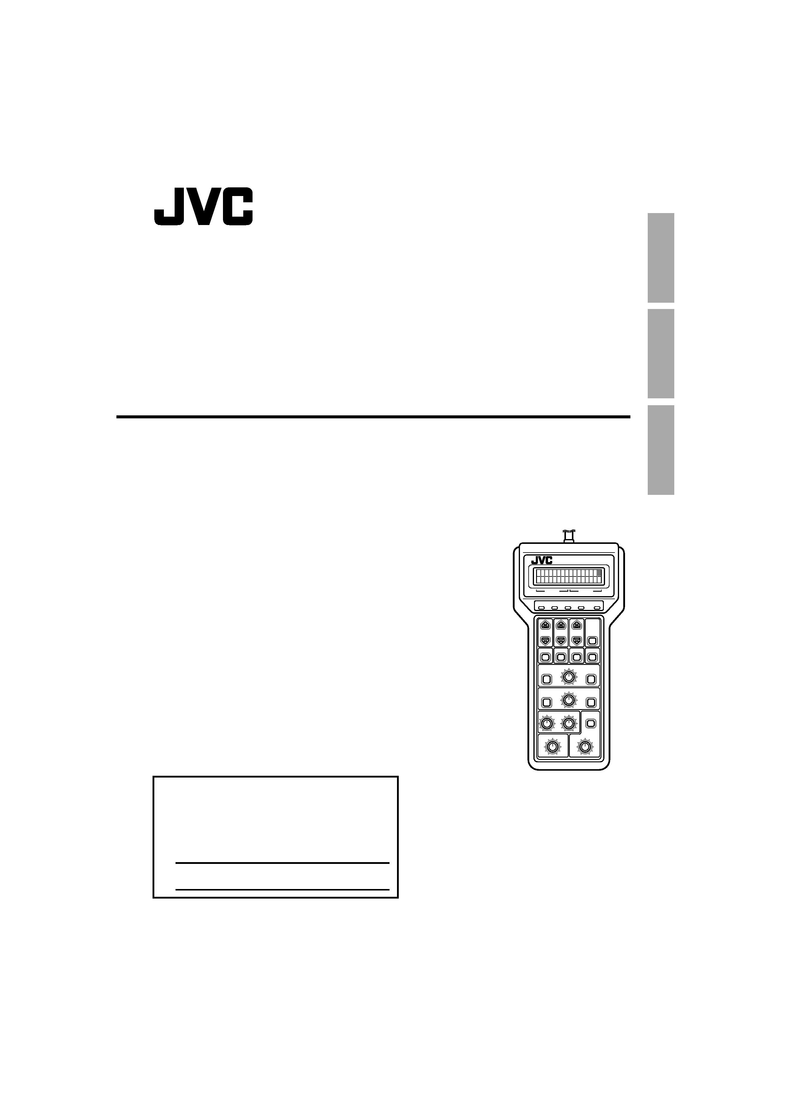
REMOTE CONTROL UNIT
RM-LP55
FUNC 2
W.PAINT
GAIN
SHUTTER IRIS MANU
OPERATE
FUNC1
W.BAL
FOCUS
SLOW
FAST
MENU
FILE
IRIS
AUTO/MANU
NEAR
FAR
ENTER
/SET
SHUTTER
FUNC2
GAIN
ZOOM
SLOW
B
FAST
WIDE
TELE
IRIS
CLOSE
OPEN
MASTER BLACK
WHITE PAINT
R
IT
ALIANO
ESP
AÑOL
FRANÇAIS
DEUTSCH
ENGLISH
LST0301-001A
REMOTE CONTROL UNIT
FERNBEDIENEINHEIT
UNITE DE TELECOMMANDE
INSTRUCTION
BEDIENUNGSANLEITUNG
MANUEL D'INSTRUCTIONS
(A)
RM-LP55
For Customer Use:
Enter below the Serial No. which is located on
the rear of the body.
Retain this information for future reference.
Model No.
RM-LP55
Serial No.
This instruction book is made from 100% recycle paper.
RM-LP55_U_E.book
Page 1
Monday, July 25, 2005
2:57 PM

E-2
Information for Users on Disposal of Old Equipment
[European Union]
This symbol indicates that the electrical and electronic equipment should not
be disposed as general household waste at its end-of-life. Instead, the
product should be handed over to the applicable collection point for the
recycling of electrical and electronic equipment for proper treatment,
recovery and recycling in accordance with your national legislation.
By disposing of this product correctly, you will help to conserve natural
resources and will help prevent potential negative effects on the environment
and human health which could otherwise be caused by inappropriate waste
handling of this product. For more information about collection point and
recycling of this product, please contact your local municipal office, your
household waste disposal service or the shop where you purchased the
product.
Penalties may be applicable for incorrect disposal of this waste, in
accordance with national legislation.
(Business users)
If you wish to dispose of this product, please visit our web page www.jvc-
europe.com to obtain information about the take-back of the product.
[Other Countries outside the European Union]
If you wish to dispose of this product, please do so in accordance with
applicable national legislation or other rules in your country for the treatment
of old electrical and electronic equipment.
Thank you for purchasing this product.
(These instructions are for RM-LP55U)
Before beginning to operate this unit, please read the instruction manual carefully in order to
make sure that the best possible performance is obtained.
The RM-LP55 is a camera remote control unit that can be connected to the JVC 3-CCD color camera for
remote operation of all major camera functions. (Maximum operating distance is about 5 m.)
For compatible cameras, refer to
ASPECIFICATIONSB (A pg. 21)
CONTENTS
FEATURES ......................................................... 3
PRECAUTIONS .................................................. 3
CONTROLS AND OPERATIONS ....................... 4
CONNECTIONS ................................................. 6
OPERATION ....................................................... 6
OPERATIONS WITH THE SETUP MENU ........ 7
OPERATIONS WITH MODE KEYS ................ 11
REMOTE CONTROLLER OPERATION
MODE SETTINGS ........................................... 18
FACTORY PRESET OF MODE SETTINGS ..... 20
System resetting method .................................. 20
SPECIFICATIONS ............................................ 21
Attention
This symbol is only valid
in the European Union.
Due to design modifications, data given in this
instruction book are subject to possible change
without prior notice.
WARNING:
TO PREVENT FIRE OR SHOCK HAZARD, DO
NOT EXPOSE THIS UNIT TO RAIN OR
MOISTURE.
POWER SYSTEM
Connection of power supply.
The RM-LP55 is designed for connection to the
JVC Color Video Camera.
Power is supplied from the video camera.
RM-LP55_U_E.book
Page 2
Monday, July 25, 2005
2:57 PM

IT
ALIANO
ESP
AÑOL
FRANÇAIS
DEUTSCH
ENGLISH
E-3
FEATURES
Setup Menu function for easy camera
preparation
The RM-LP55's easy-to-use Setup Menu
function lets you make all necessary camera
settings while referring to the remote's LCD
panel.
Easy-to-see LCD indications
Operation status can be displayed on the LCD
for at-a-glance checking of current camera
settings. The display is backlit so indications
are clear and easy to read even in the dark.
AScene FileB function
You can store two different sets of setting data
in the remote control's memory which can be
called up whenever necessary and applied
directly to the connected camera.
PRECAUTIONS
o Safety precautions
Be sure that no inflammable materials, liquids,
or metal objects are introduced into the
RM-LP55. This may damage the internal
circuitry and lead to failure.
Never use the RM-LP55 if it has been modified
or the cover has been removed.
If the RM-LP55 behaves abnormally (emits
strange sounds, odors, or smoke), cut off the
power immediately and contact your nearest
JVC-authorized service agent.
o Handling the unit
Operating environment
Do not install or use the camera in the following
locations.
Places exposed to rain or water
Places containing vapor or oil soot, such as
kitchens
Places exceeding the operating ambient
temperature range (0° to 40°)
Places where corrosive gases are generated
Places nearby radiation or X-rays as well as
sources of strong radio waves or magnetism
Places subject to vibration
Places with excessive dust
Ambient temperature:
Observe the ambient temperature range as
described in the Specifications on page 21.
External care of the RM-LP55:
Gently wipe off dust with a soft dry cloth (such
as flannel). If the unit is extremely dirty, dip a
soft cloth into a detergent solution diluted with
water, wring it thoroughly, then wipe the dirt off.
Dry the unit with a dry cloth. Do not use a rag
treated with chemicals or allow volatile liquids
such as benzine, thinner, alcohol, etc., to come
in contact with the RM-LP55. This may mar the
finish or the damage the coating.
Where there are strong electromagnetic waves
or magnetism, for example near a radio or TV
transmitter, transformer, motor, etc., the picture
may contain noise and the colors may be
incorrect.
RM-LP55_U_E.book
Page 3
Monday, July 25, 2005
2:57 PM

E-4
CONTROLS AND OPERATIONS
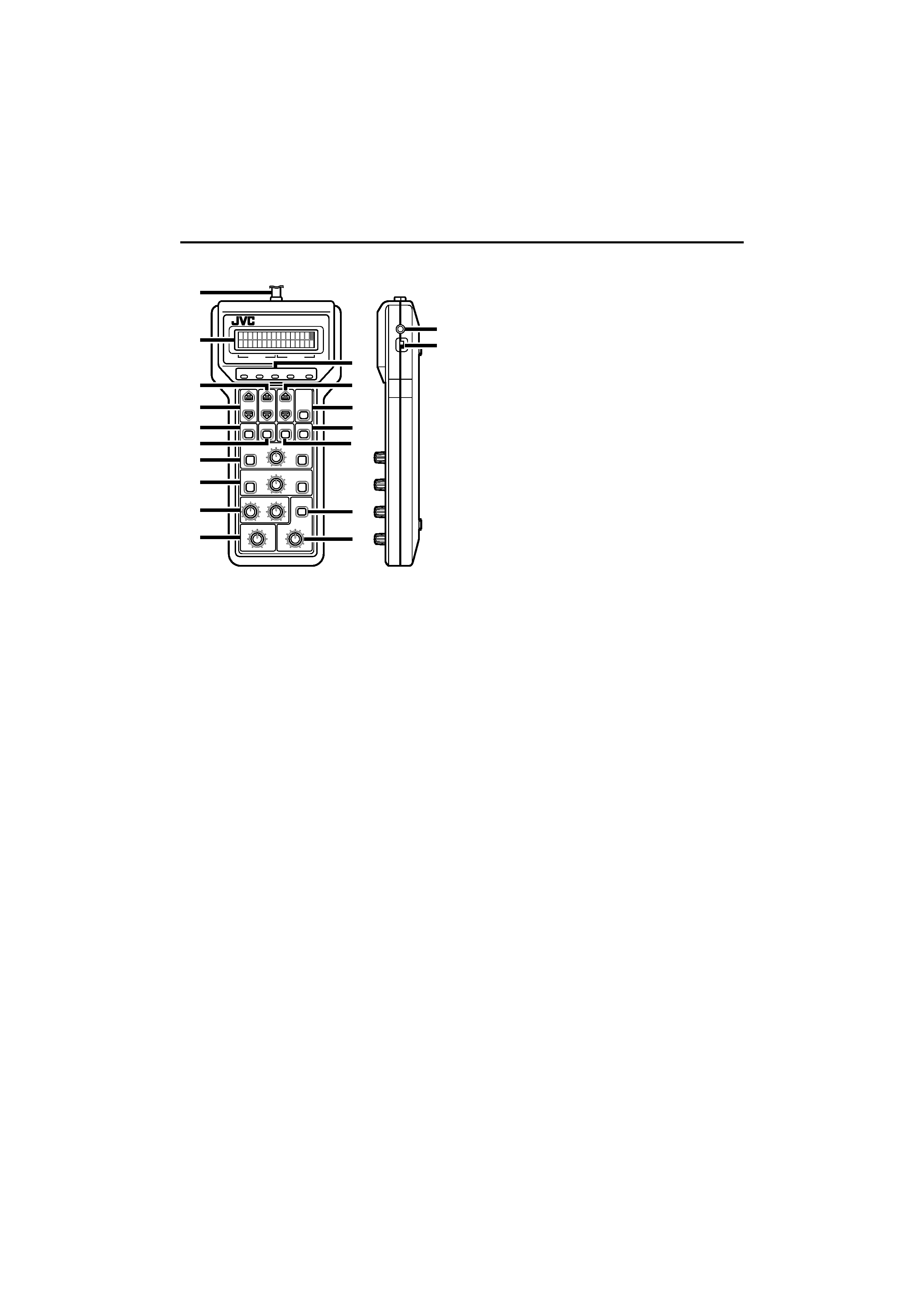
Front & side views with callouts
A [OPERATE] switch
ON
: Set to this position to control the
camera with the RM-LP55.
OFF
: Set to this position to disable the
RM-LP55's camera control capability.
B [MENU] buttons
Calls up Setup Menu items on the LCD panel.
The Menu item changes each time the button
is pressed. Hold the button depressed to
change Menu items in succession.
C [FUNC1] buttons
Selects the mode or sets the level for the Setup
Menu according to the function of each item.
D [FUNC2] buttons
Selects the Setup Menu mode according to the
function of each item.
E [ENTER/SET] button
This is a multi-function button. Differs from
Menu items. (See each item's setting
procedure for details.)
1. During white balance adjustment: Activates
auto white balance adjustment.
2. During title setting: Executes the title
setting.
3. During Scene File operation: Executes the
Scene File function.
F [FILE] button
Calls up the display for Scene File function.
FUNC 1
REMOTE CONTROL UNIT
RM-LP55
CONTRAST ON
OFF
OPERA
TE
FUNC 2
W.PAINT
GAIN
SHUTTER IRIS MANU OPERATE
FUNC1
W.BAL
FOCUS
SLOW
FAST
MENU
FILE
IRIS
AUTO/MANU
NEAR
FAR
ENTER
/SET
SHUTTER
FUNC2
GAIN
ZOOM
SLOW
B
FAST
WIDE
TELE
IRIS
CLOSE
OPEN
MASTER BLACK
WHITE PAINT
R
J
B
C
I
E
M
N
D
P
K
L
O
Q
S
R
A
F
G
H
RM-LP55_U_E.book
Page 4
Monday, July 25, 2005
2:57 PM

IT
ALIANO
ESP
AÑOL
FRANÇAIS
DEUTSCH
ENGLISH
E-5
G [W.BAL] button
Calls up the display for white balance
adjustment.
H [GAIN] button
Calls up the display for gain setting.
I [SHUTTER] button
Calls up the display for shutter speed setting.
J [FOCUS] control with [NEAR/FAR] buttons
Varies focus control speed. Focus length can
be set with the NEAR and FAR buttons.
NEAR : To set focus on a close object.
FAR
: To set focus on a distant object.
K [ZOOM] control with [WIDE/TELE] buttons
Varies zoom control speed. Picture angle can
be set with the WIDE and TELE buttons.
WIDE
: To set to wide angle.
TELE
: To set to telephoto angle.
L [WHITE PAINT] controls
1. Adjusts the R or B channel's gain level
when the white balance mode is set to
AMANUALB.
2. When PNT is set to ON with the white
balance mode set to
AAUTO1B or AAUTO2B,
these controls are used to vary the R or B
channel's gain level for more precise
adjustment.
M [IRIS AUTO/MANU] button
Switches iris mode between auto and manual.
N [IRIS] control
Adjusts the iris while in the manual iris mode.
Setting range is from near the CLOSE position
to the OPEN position.
Also used for precise adjustment of the auto
iris level while in the auto iris mode.
O [MASTER BLACK] control
Adjusts the master black level.
P LED indicators
Light to indicate the current status for each
item.
OPERATE
: Lights green when the remote
control is ready to use.
W.PAINT
: Lights amber when the white
balance mode is set to
AAUTO1B
or
AAUTO2B with APNT ONB
selected.
GAIN
: Lights amber when the gain
mode is set to other than
A0dBB.
SHUTTER
: Lights amber when the shutter
mode is set to modes other than
ANORMALB. (If the AV.SCANB
shutter mode is set to
A1/60.0
(1/50.0 for E version model)
B,
the LED doesn't light.)
IRIS MANU : Lights amber while in the
manual iris mode.
Q LCD Panel
Displays various mode, status, and setting data
including Setup Menu, setting mode, setting
level, and warning messages.
R [CONTRAST] control
Adjusts the LCD's contrast.
S Cable (5 m)
Connects the remote control unit to a camera.
RM-LP55_U_E.book
Page 5
Monday, July 25, 2005
2:57 PM
