SERVICE MANUAL
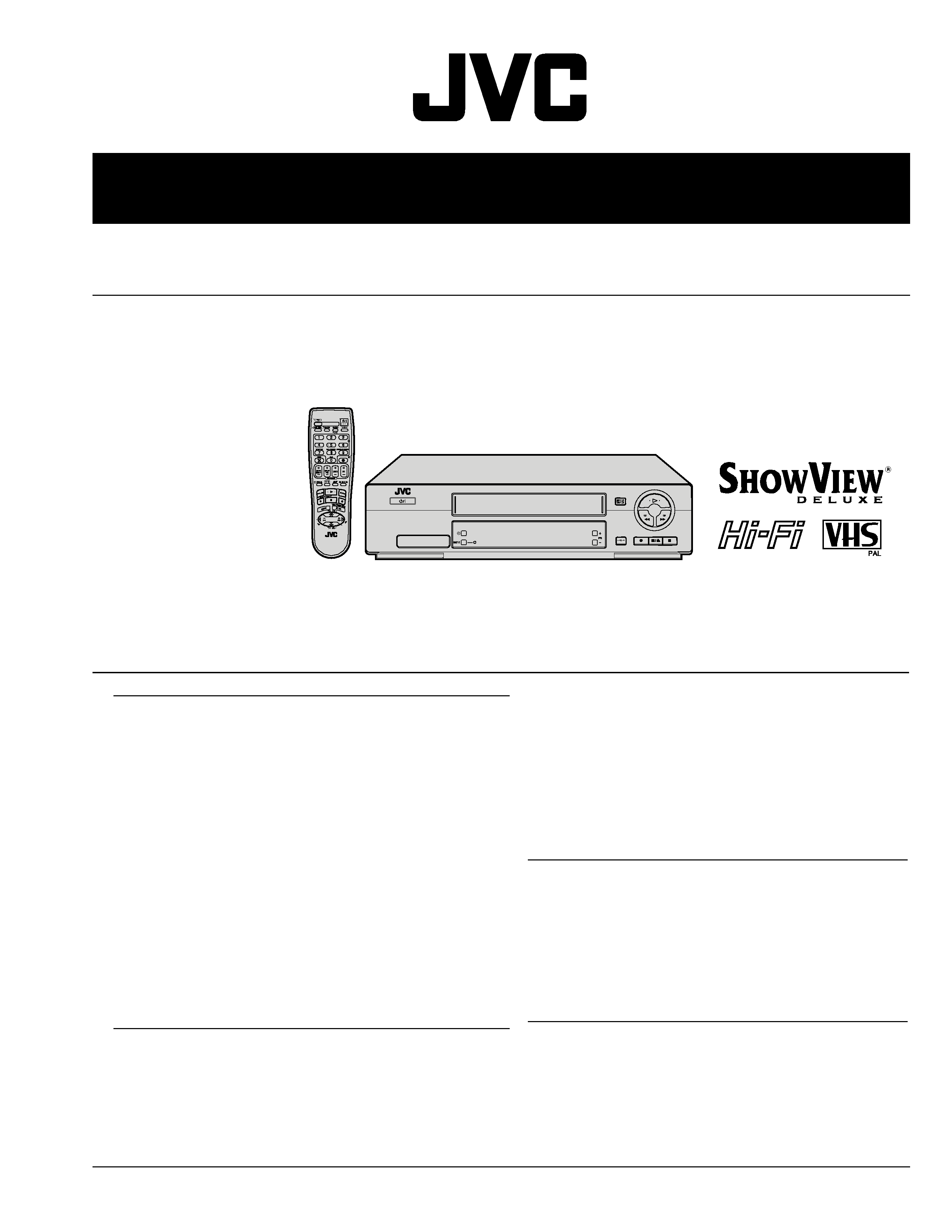
VIDEO CASSETTE RECORDER
No. 82815
July 2000
This service manual is printed on 100% recycled paper.
COPYRIGHT © 2000 VICTOR COMPANY OF JAPAN, LTD.
HR-J671EU/J672EK/J674EU
Regarding service information other than these sections, refer to the HR-J670EK/EU service manual (No. 82784).
Also, be sure to note important safety precautions provided in the service manual.
SPECIFICATIONS
(The specifications shown pertain specifically to the model
HR-J670EU/J671EU/J672EU/J673EU/J674EU, HR-J470EU/J472EU, HR-J270EU/J272EU)
GENERAL
Power requirement
: AC 220 V 240 V` , 50 Hz/60 Hz
Power consumption
[HR-J670/671/672/673/674EU]
Power on
: 19 W
Power off
: 4.9 W
[HR-J470/472/270/272EU]
Power on
: 17 W
Power off
: 4.9 W
Temperature
Operating
: 5
°C to 40°C
Storage
: 20
°C to 60°C
Operating position
: Horizontal only
Dimensions (WxHxD) : 400 x 94 x 278 mm
Weight
: 3.5 kg
Format
: VHS PAL standard
Maximum recording time
(SP)
: 240 min. with E-240 video cassette
(LP) [HR-J670/671/672/673/674/470/472EU only]
: 480 min. with E-240 video cassette
VIDEO/AUDIO
Signal system
: PAL-type colour signal and CCIR
monochrome signal, 625 lines 50 fields
Recording system
: DA4 (Double Azimuth) head helical
scan system [HR-J670/671/672/673/
674/470/472EU]
Rotary two-head herical scan system
[HR-J270/272EU]
Signal-to-noise ratio
: 45 dB
Horizontal resolution
: 250 lines
Frequency range
: 70 Hz to 10,000 Hz (Normal audio)
20 Hz to 20,000 Hz (Hi-Fi audio)
[HR-J670/671/672/673/674EU only]
Input/Output
: 21-pin SCART connectors :
IN/OUT x 1, IN/DECODER x 1
RCA connectors
: AUDIO OUT x 1
[HR-J670/671/672/673/674EU only]
TUNER/TIMER
TV channel storage capacity
: 99 positions (+AUX position)
Tuning system
: Frequency synthesized tuner
Channel coverage
: VHF 47 89/104 300/
302 470MHz
UHF 470 862MHz
Aerial output
: UHF channels 22 69 (Adjustable)
Memory backup time
: Approx. 10 min.
ACCESSORIES
Provided accessories
: RF cable,
Infrared remote control unit,
"R6" battery x 2
Optional accessories
: Satellite Controller RM-SD1
Specifications shown are for SP mode unless otherwise specified.
E.& O.E. Design and specifications subject to change without notice.

TABLE OF CONTENTS
DIFFERENT TABLE .................................................................................................................................................................. 1
4. CHARTS AND DIAGRAMS (4-1 to 4-6)
4.1
MAIN, A/C HEAD, R.PAUSE, MINI OPE AND LOADING MOTOR CIRCUIT BOARDS ............................................... 4-2
4.2
DEMODULATOR SCHEMATIC DIAGRAM ................................................................................................................... 4-4
4.3
DEMODULATOR CIRCUIT BOARD ............................................................................................................................. 4-6
5. PARTS LIST (5-1 only)
5.1
ELECTRICAL PARTS LIST ........................................................................................................................................... 5-1
DEMODULATOR BOARD ASSEMBLY ................................................................................................................................ 5-1
[HR-J671EU/J674EU/J672EK]
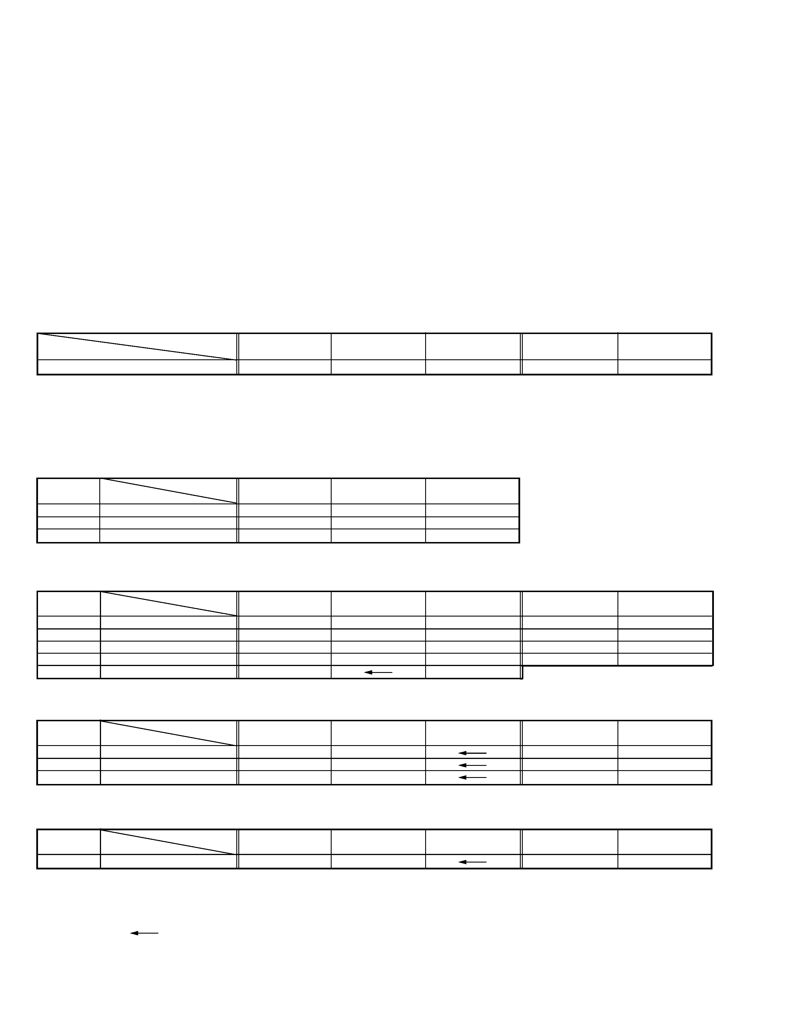
The following table indicate main different points between models HR-J670EU, HR-J671EU, HR-J674EU, HR-J670EK and HR-J672EK.
1
MODEL
HR-J670EU
HR-J671EU
HR-J674EU
HR-J670EK
HR-J672EK
ITEM
FRONT PANEL COLOR
SILVER
BLACK & GOLD
SILVER
SILVER
BLACK & L.GLAY
The following table indicate different parts number between models HR-J670EU, HR-J671EU, HR-J674EU, HR-J670EK and HR-J672EK.
!
REF.
MODEL
HR-J670EU
HR-J671EU
HR-J674EU
NO.
ITEM
! 310
INST.BOOK(CZ)
LPT0322-013A
--
--
! 310
INST.BOOK(PO)
LPT0322-014A
--
--
! 310
INST.BOOK(HU)
LPT0322-015A
--
--
PACKING AND ACCESSORY ASSEMBLY <M1>
!
REF.
MODEL
HR-J670EU
HR-J671EU
HR-J674EU
HR-J670EK
HR-J672EK
NO.
ITEM
! 501
FRONT PANEL ASSY
LP10289-003D
LP10289-049B
LP10289-048B
LP10289-009B
LP10289-050C
501A
CASSETTE DOOR
LP20868-002A
LP20868-029A
LP20868-028A
LP20868-002A
LP20868-029A
501C
DISPLAY WINDOW
LP20869-003A
LP20869-071A
LP20869-070A
LP20869-009A
LP20869-072A
! 502
TOP COVER
LP10013-017C
LP10013-023D
LP10013-051A
LP10013-017C
LP10013-023D
503
TAP SCREW
QYTDSF3010M
QYTDSF3010R
CABINET AND CHASSIS ASSEMBLY <M2>
!
REF.
MODEL
HR-J670EU
HR-J671EU
HR-J674EU
HR-J670EK
HR-J672EK
NO.
ITEM
PW1
MAIN BOARD ASSY
LPA10086-02E1
LPA10086-02H1
LPA10086-03E1
LPA10086-03H1
IC1
IC
*JCP8020-MSB
JCP8020-MSD-2
*JCP8020-MSB
JCP8020-MSD-2
D5301
ZENER DIODE
*MTZJ15A
MTZJ15C
*MTZJ15A
MTZJ15C
MAIN BOARD ASSEMBLY <03>
!
REF.
MODEL
HR-J670EU
HR-J671EU
HR-J674EU
HR-J670EK
HR-J672EK
NO.
ITEM
PW1
DEMOD BOARD ASSY
*LPA10060-03B
LPA10094-02A
*LPA10060-03B
LPA10094-02A
DEMOD BOARD ASSEMBLY <14>
Notes : Mark -- is not used.
Mark
is same as left.
Mark * reference model was also changed.

Printed in Japan
VICTOR COMPANY OF JAPAN, LIMITED
VIDEO DIVISION
S40894
