SERVICE MANUAL
No.82852
April 2001
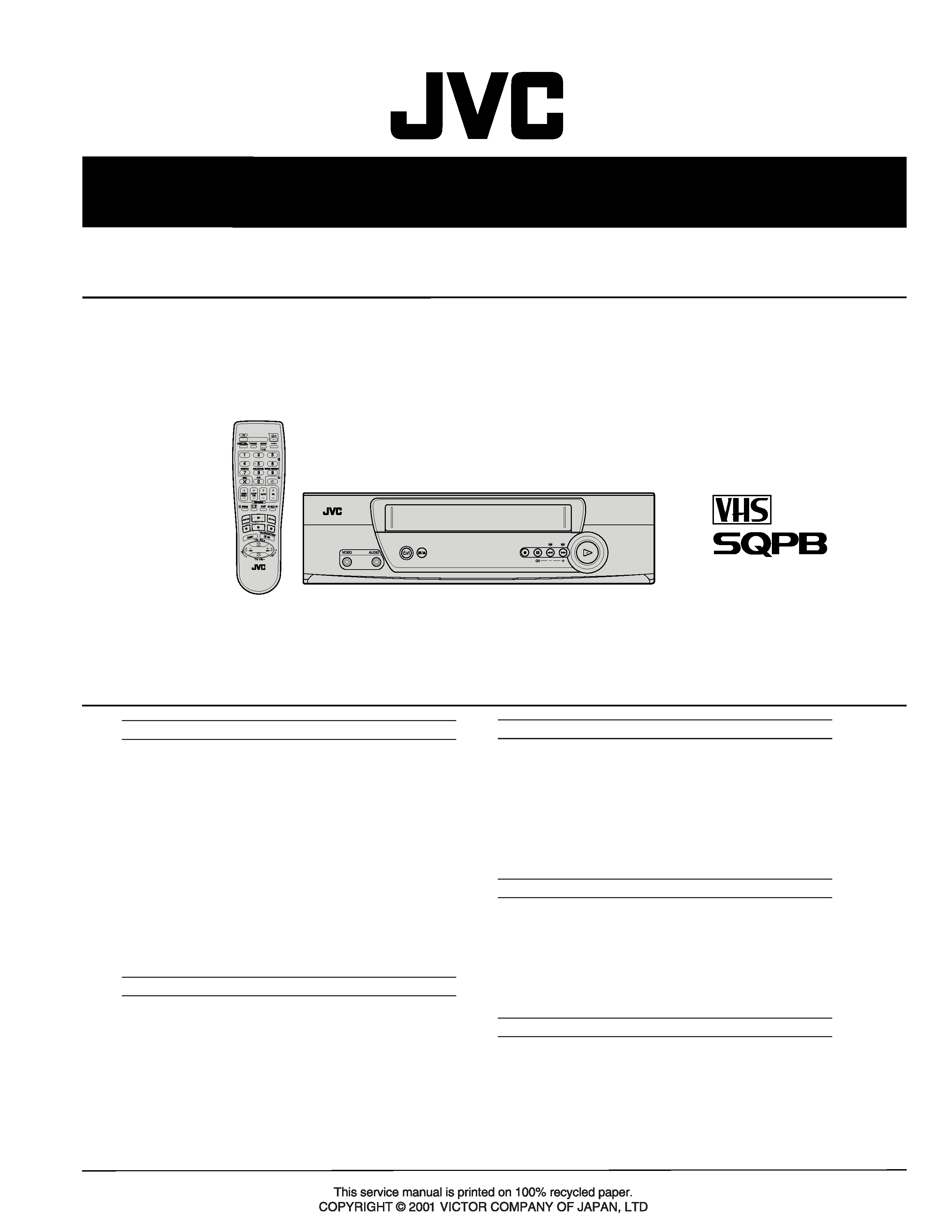
HR-J3008UM/J4008UM
VIDEO CASSETTE RECORDER
Regarding service information other than these sections, refer to the HR-A37U service manual (No.82836).
Also, be sure to note important safety precautions provided in the service manual.
SPECIFICATIONS (The specifications shown pertain specifically to the model HR-J4008UM)
Specifications shown are for SP mode unless specified otherwise.
E. & O.E. Design and specifications subject to change without
notice.
GENERAL
Power requirement
: AC 110 V 220 Vd, 50 Hz/60 Hz
Power consumption
Power on
: 14 W
Power off
: 2.0 W
Temperature
Operating
: 5
°C to 40°C
Storage
: 20
°C to 60°C
Operating position
: Horizontal only
Dimensions (W x H x D) : 360 mm x 94 mm x 247 mm
Weight
: 3.0 kg
Format
: VHS NTSC standard
Maximum recording time
SP
: 210 min. with ST-210 video cassette
EP
: 630 min. with ST-210 video cassette
VIDEO/AUDIO
Signal system
: NTSC-type color signal and EIA
monochrome signal, 525 lines/
60 fields
Recording/Playback
system
: DA-4 (Double Azimuth) head helical
scan system
Signal-to-noise ratio
: 45 dB
Horizontal resolution
: 230 lines
Frequency range
: 70 Hz to 10,000 Hz
Input/Output
: RCA connectors (IN x 1, OUT x 1)
TUNER
Tuning system
: Frequency-synthesized tuner
Channel coverage
VHF
: Channels 213
UHF
: Channels 1469
CATV
: 113 Channels
RF output
: Channel 3 or 4 (switchable; preset to
Channel 3 when shipped) 75 ohms,
unbalanced
TIMER
Clock reference
: Quartz
Program capacity
: 1-year programmable timer/
8 programs
Memory backup time
: Approx. 6 months
Estimated figure based on supplied
fresh battery; actual performance may
differ.
ACCESSORIES
Provided accessories
: RF cable (F-type),
Lithium battery CR2025,
Infrared remote control unit,
"AA" battery x 2,
Conversion plug
TABLE OF CONTENTS
Section
Title
Page
Section
Title
Page
DIFFERENT TABLE ........................................................................... 1 to 2
2. MECHANISM ADJUSTMENT
2.1
Before starting repair and adjustment ........................................... 2-1
2.1.1Precautions ................................................................................... 2-1
2.1.2Checking for proper mechanical operations ................................. 2-1
2.1.3Manually removing the cassette tape ........................................... 2-1
2.1.4Jigs and tools required for adjustment .......................................... 2-2
2.1.5Maintenance and inspection ......................................................... 2-3
2.2
Replacement of major parts .......................................................... 2-6
2.2.1Before starting disassembling
(Phase matching between mechanical parts) ......................... 2-6
2.2.2How to set the "Mechanism assembling mode" ............................ 2-6
2.2.3Cassette holder assembly ............................................................ 2-6
2.2.4Pinch roller arm assembly ............................................................ 2-8
2.2.5Guide arm assembly and press lever assembly ........................... 2-8
2.2.6A/C head ....................................................................................... 2-8
2.2.7Loading motor ............................................................................... 2-8
2.2.8Capstan motor .............................................................................. 2-9
2.2.9Pole base assembly (supply or take-up side) ............................... 2-9
2.2.10
Rotary encoder ..................................................................... 2-10
2.2.11
Clutch unit ............................................................................. 2-10
2.2.12
Change lever assembly,direct gear,clutch gear
and coupling gear ................................................................. 2-10
2.2.13
Link lever ............................................................................... 2-11
2.2.14
Cassette gear,control cam and worm gear ........................... 2-11
2.2.15
Control plate .......................................................................... 2-11
2.2.16
Loading arm gear (supply or take-up side)
and loading arm gear shaft ................................................... 2-12
2.2.17
Take-up lever,take-up head and control plate guide ............. 2-13
2.2.18
Capstan brake assembly ...................................................... 2-13
2.2.19
Sub brake assembly (take-up side) ...................................... 2-13
2.2.20
Main brake assembly (take-up side),
reel disk (take-up side) and
main brake assembly (supply side) ....................................... 2-13
2.2.21
Tension brake assembly, reel disk (supply side)
and tension arm assembly .................................................... 2-14
2.2.22
Idler lever, idler arm assembly .............................................. 2-14
2.2.23
Stator assembly .................................................................... 2-14
2.2.24
Rotor assembly ..................................................................... 2-14
2.2.25
Upper drum assembly ........................................................... 2-15
2.3
Compatibility adjustment ............................................................. 2-16
2.3.1FM waveform linearity ................................................................. 2-16
2.3.2Height and tilt of the A/C head .................................................... 2-17
2.3.3A/C head phase (X-value) .......................................................... 2-17
2.3.4Standard tracking preset ............................................................. 2-18
2.3.5Tension pole position .................................................................. 2-18
4. CHARTS AND DIAGRAMS
4.1
MAIN (SYSCOM) AND LT BATTERY
SCHEMATIC DIAGRAMS ....................................................... 4-1
4.2
MAIN CIRCUIT BOARD
(MAIN PWB LPB10130-001C) [HR-J4008UM] ............................. 4-3
4.3
MAIN CIRCUIT BOARD
(MAIN PWB LPB10130-001D) [HR-J3008UM] ............................. 4-5
5. PARTS LIST
5.1
PACKING AND ACCESSORY ASSEMBLY <M1> ........................ 5-1
5.2
FINAL ASSEMBLY <M2> .............................................................. 5-2
5.3
MECHANISM ASSEMBLY <M4> .................................................. 5-4
5.4
ELECTRICAL PARTS LIST .......................................................... 5-6
MAIN BOARD ASSEMBLY <03> .................................................. 5-6
A/C HEAD BOARD ASSEMBLY <12>. ....................................... 5-10
LOADING MOTOR BOARD ASSEMBLY <55> .......................... 5-10
LT BATTERY BOARD ASSEMBLY <93>
[HR-J4008UM] ....................................................................... 510
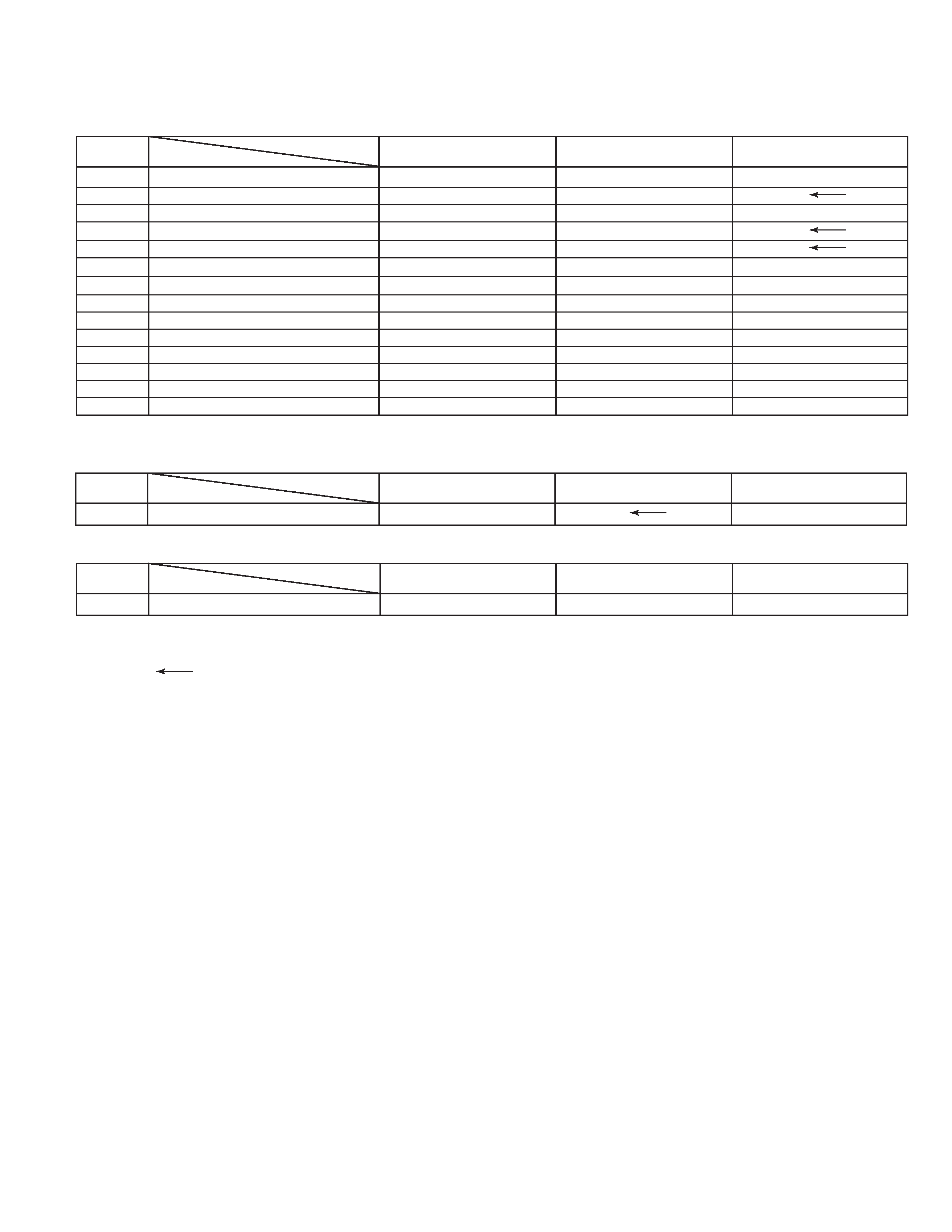
The following table indicate main different points between models HR-A37U,HR-J3008UM and HR-J4008UM.
PACKING AND ACCESSORY ASSEMBLY <M1>
REF
NO.
!
MODEL
HR-A37U
HR-J3008UM
ITEM
301
PACKING CASE
LP30836-006A
LP30836-017A
LP30836-015B
306
REMOTE CONTROL UNIT
LP20878-001A
LP20878-002A
306A
COVER(BATTERY)
LP40610-001A
LP40610-002A
! 309
LITHIUM BATTERY
PECA0903
! 310
INST. BOOK(EN)
LPT0497-001A
LPT0533-001A
! 310
INST. BOOK(SP)
LPT0532-001A
LPT0533-002A
311
POLY BAG
QPC02503530P
! 313
CONVERSION PLUG
PEMC1012
317
REGIST. CARD
BT-51020-2
320
CONNECTION SHEET
PU36560-2
HR-J4008UM
Note: Mark
is same as left.
1
The following table indicate main different points between models HR-A37U,HR-J3008UM and HR-J4008UM.
MODEL
HR-A37U
HR-J3008UM
ITEM
POWER VOLTAGE
120V, 60HZ
110-220V, 50/60HZ
POWER PLUG
UL, CSA
SASO
COSMETIC/COLOR
MOLD-DARK GRAY
PAINT-Pure SILVER
RCU TYPE / COLOR
U1 / MOLD BLACK
E1 / PAINT SILVER
INSTRUCTION / LANGUAGE
1 SHEET / ENG
YES / SPA
YES / SPA, ENG
PLUG ADAPTER
NOT USED
SASO
CEE
LITHIUM BATTERY
NOT USED
CR2025
HEAD CLEANER
NOT USED
USED
SHUTTLE SERCH(LATCH)
SPX7, EPX21
SPX7, EPX21(X21)
B.E.S.T. PICTURE
AUTO PICTURE
A.V. CALIBRATION
AUTO CH PRESET
USED (P&P)
USED
BACKUP TIME
NOT USED
6 MONTHS(LI BATT.)
TIMER PROGRAM BACKUP
PERMANENT PROGRAM
NOT USED
SUMMER TIME ADJUST
USED
NOT USED
AUTO CLOCK / JUST CLOCK
USED
NOT USED
REC RESUME
NOT USED
USED
LANGUAGE[INITIAL]
[ENG], SPA, FRE
[SPA], ENG
HR-J4008UM
Note: Mark is not used.
Mark
is same as left.
2
FINAL ASSEMBLY<M2>
REF
NO.
!
MODEL
HR-A37U
HR-J3008UM
ITEM
! 501
FRONT PANELASSEMBLY
* LP10348-004D
LP10348-009F
LP10348-008F
501A
CASSETTE DOOR
* LP20977-002C
LP20977-008C
501C
DISPLAY WINDOW
LP20976-004A
LP20976-009A
LP20976-008A
! 502
TOP COVER
LP10352-002A
LP10352-008A
503
SCREW,X2,TOP COVER(SIDE)
QYTDSF3010M
QYTDSF3010R
! 511
BOTTOM CHASSIS
* LP10350-003D
LP10350-004D
LP10350-005D
! 517
POWER CORD
QMP73J0-170
518
CLEANER ASSEMBLY
LP40369-001D
518A
CLEANER ROLLER
PQ46418-1-2
518B
CLEANER
PQ46419-1-2
518C
CLEANER ARM
LP30407-001D
520
CAP
LP30336-001A
531
SCREW,REAR
QYTDSF3010M
532
SCREW,TERMINAL BOARD
QYTDSF3010Z
HR-J4008UM
Note : Mark is not used.
Mark
is same as left.
Mark * reference model was also changed.
MAIN BOARD ASSEMBLY<03>
REF
NO.
!
MODEL
HR-A37U
HR-J3008UM
ITEM
PW1
MAIN BOARD ASSEMBLY
* LPA10130-02D1
LPA10130-05B1
HR-J4008UM
LITHIUM BATTERY BOARD ASSEMBLY<93>
REF
NO.
!
MODEL
HR-A37U
HR-J3008UM
ITEM
! PW4
LITHIUM BATTERY BOARD ASSEMBLY
LPA10130-01A4
HR-J4008UM
2-1
SECTION 2
MECHANISM ADJUSTMENT
2.1 Before starting repair and adjustment
2.1.1
Precautions
(1) Unplug the power cord plug of the VCR before using your
soldering iron.
(2) Take care not to cause any damage to the conductor
wires when plugging and unplugging the connectors.
(3) Do not randomly handle the parts without identifying
where the trouble is.
(4) Exercise enough care not to damage the lugs, etc. dur-
ing the repair work.
(5) When reattaching the front panel assembly, make sure
that the door opener of the cassette holder assembly is
lowered in position prior to the reinstallation. (See SEC-
TION 1 DISASSEMBLY.)
(6) When using the Jig RCU, it is required to set the VCR to
the Jig RCU mode (the mode in which codes from the
Jig RCU can be received). (See SECTION 1 DISASSEM-
BLY.)
2.1.2
Checking for proper mechanical operations
Enter the mechanism service mode when you want to oper-
ate the mechanism when no cassette is loaded. (See SEC-
TION 1 DISASSEMBLY.)
2.1.3
Manually removing the cassette tape
1. In case of electrical failures
If you cannot remove the cassette tape which is loaded be-
cause of any electrical failure, manually remove it by taking
the following steps.
(1) Unplug the power cord plug from the power outlet.
(2) Refer to the disassembly procedure and perform the dis-
assembly of the major parts before removing the drum
assembly.
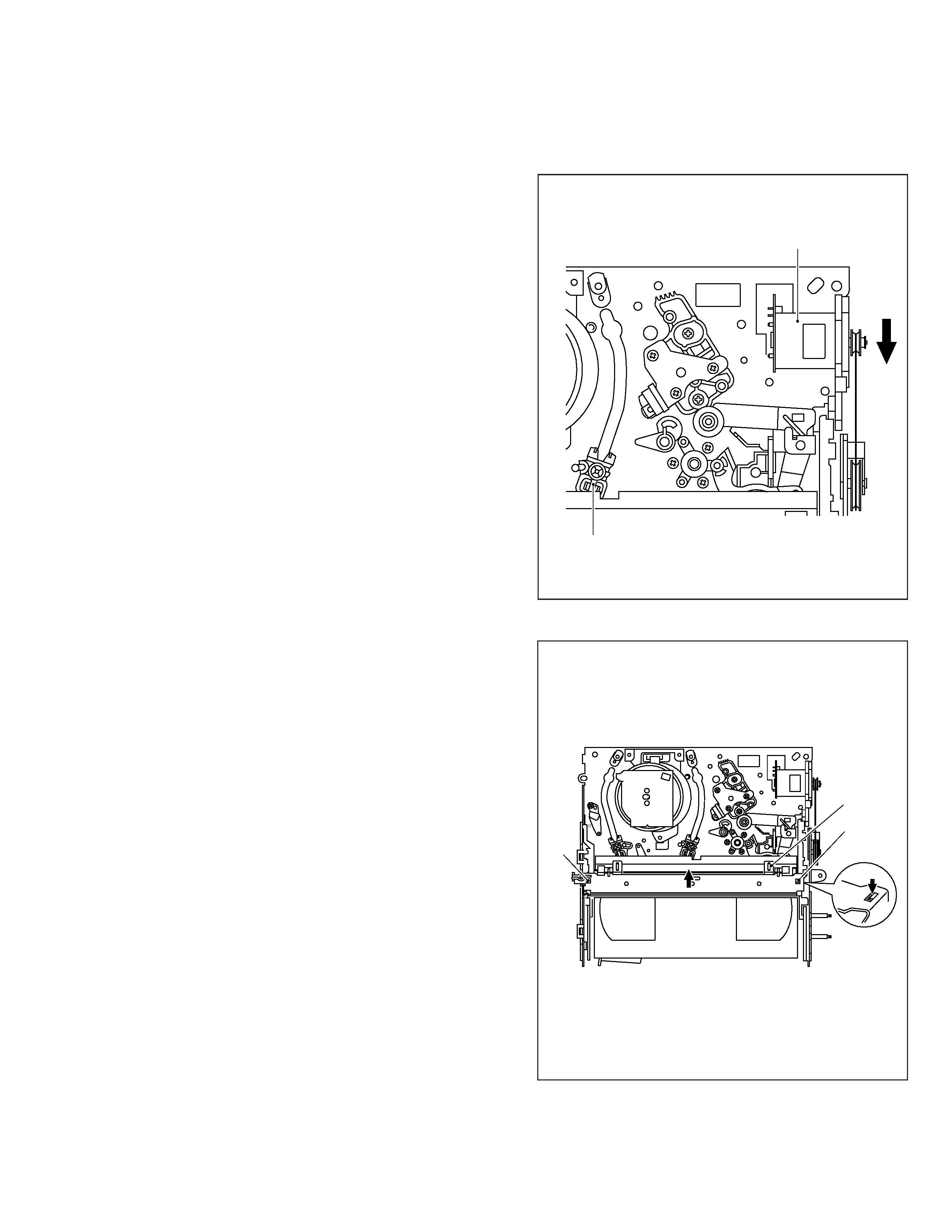
(3) Unload the pole base assembly by manually turning the
loading motor of the mechanism assembly toward the
front. In doing so, hold the tape by the hand to keep the
slack away from any grease. (See Fig.2-1-3a.)
(4) Bring the pole base assembly to a pause when it reaches
the position where it is hidden behind the cassette tape.
(5) Move the top guide toward the drum while holding down
the lug (A) of the bracket retaining the top guide. Like-
wise hold part (B) down and remove the top guide.
Section (C) of the top guide is then brought under the
cassette lid. Then remove the top guide by pressing the
whole cassette tape down. (See Fig.2-1-3b.)
(6) Remove the cassette tape by holding both the slackened
tape and the cassette lid.
(7) Take up the slack of the tape into the cassette. This com-
pletes removal of the cassette tape.
Note:
· For the disassembly procedure of the major parts and
details of the precautions to be taken, see "SECTION
1 DISASSEMBLY".
Fig. 2-1-3b
Fig. 2-1-3a
Loading motor
Pole base assembly
Press
(C)
(A)
(B)
2-2
2. In case of mechanical failure
If you cannot remove the cassette tape which is loaded be-
cause of any mechanical failure, manually remove it by tak-
ing the following steps.
(1) Unplug the power cable and remove the top cover, front
panel assembly and others so that the mechanism as-
sembly is visible. (See SECTION 1 DASASSEMBLY.)
(2) While keeping the tension arm assembly of the mecha-
nism assembly free from tension, pull the tape on the pole
base assembly (supply or take-up side) out of the guide
roller. (See Fig.2-1-3c.)
(3) Take the spring of the pinch roller arm assembly off the
hook of the press lever assembly, and detach it from the
tape. (See Fig.2-1-3d.)
(4) In the same way as in the electrical failure instructions in
2.1.3-1(5), remove the top guide.
(5) Raise the cassette tape cover. By keeping it in that posi-
tion, draw out the cassette tape case from the cassette
holder and take out the tape.
(6) By hanging the pinch roller arm assembly spring back
on the hook, take up the slack of the tape into the cas-
sette.
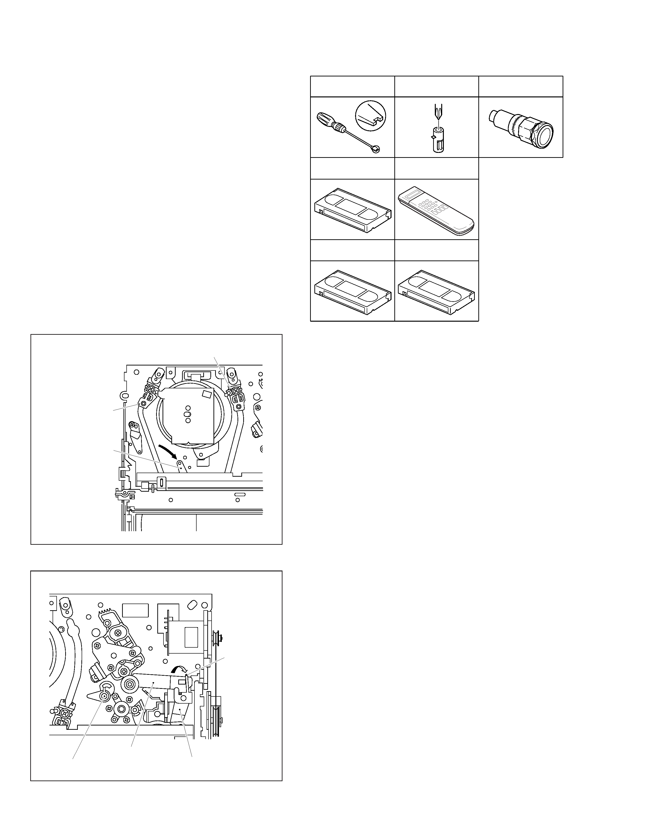
Fig. 2-1-3d
Fig. 2-1-3c
Pole base assembly (take-up side)
Pole base assembly
(supply side)
Tension arm assembly
Guide pole guard
Pinch roller arm assembly
Press lever assembly
Take the spring
off the hook, and
detach it from the
tape.
2.1.4
Jigs and tools required for adjustment
Roller driver
PTU94002
A/C head positioning tool
PTU94010
Back tension cassette gauge
PUJ48076-2
Jig RCU
PTU94023B
Torque gauge
PUJ48075-2
Alignment tape
(SP, stairstep, NTSC)
MHP
Alignment tape
(EP, stairstep, NTSC)
MHP-L
