SERVICE MANUAL
COPYRIGHT © 2004 Victor Company of Japan, Limited
No.YF059
2004/11
DIGITAL MEDIA CAMERA
YF059
2004
11
GZ-MC200US
TABLE OF CONTENTS
1
PRECAUTIONS . . . . . . . . . . . . . . . . . . . . . . . . . . . . . . . . . . . . . . . . . . . . . . . . . . . . . . . . . . . . . . . . . . . . . . . 1-3
2
SPECIFIC SERVICE INSTRUCTIONS . . . . . . . . . . . . . . . . . . . . . . . . . . . . . . . . . . . . . . . . . . . . . . . . . . . . . . 1-5
3
DISASSEMBLY . . . . . . . . . . . . . . . . . . . . . . . . . . . . . . . . . . . . . . . . . . . . . . . . . . . . . . . . . . . . . . . . . . . . . . 1-21
4
ADJUSTMENT . . . . . . . . . . . . . . . . . . . . . . . . . . . . . . . . . . . . . . . . . . . . . . . . . . . . . . . . . . . . . . . . . . . . . . . 1-35
5
TROUBLE SHOOTING. . . . . . . . . . . . . . . . . . . . . . . . . . . . . . . . . . . . . . . . . . . . . . . . . . . . . . . . . . . . . . . . . 1-37
GZ-MC200US [M4S527]
1-2 (No.YF059)
SPECIFICATION
(No.YF059)1-3
SECTION 1
PRECAUTIONS
1.1
SAFTY PRECAUTIONS
Prior to shipment from the factory, JVC products are strictly
inspected to conform with the recognized product safety and
electrical codes of the countries in which they are to be
sold.However,in order to maintain such compliance, it is equally
important to implement the following precautions when a set is
being serviced.
1.1.1 Precautions during Servicing
(1) Locations requiring special caution are denoted by labels
and inscriptions on the cabinet, chassis and certain parts of
the product.When performing service, be sure to read and
comply with these and other cautionary notices appearing
in the operation and service manuals.
(2) Parts identified by the
symbol and shaded (
) parts
are critical for safety.
Replace only with specified part numbers.
NOTE :
Parts in this category also include those specified to
comply with X-ray emission standards for products
using cathode ray tubes and those specified for
compliance with various regulations regarding
spurious radiation emission.
(3) Fuse replacement caution notice.
Caution for continued protection against fire hazard.
Replace only with same type and rated fuse(s) as
specified.
(4) Use specified internal wiring. Note especially:
· Wires covered with PVC tubing
· Double insulated wires
· High voltage leads
(5) Use specified insulating materials for hazardous live parts.
Note especially:
· Insulation Tape
· PVC tubing
·Spacers
· Insulation sheets for transistors
·Barrier
(6) When replacing AC primary side components (transformers,
power cords, noise blocking capacitors, etc.) wrap ends of
wires securely about the terminals before soldering.
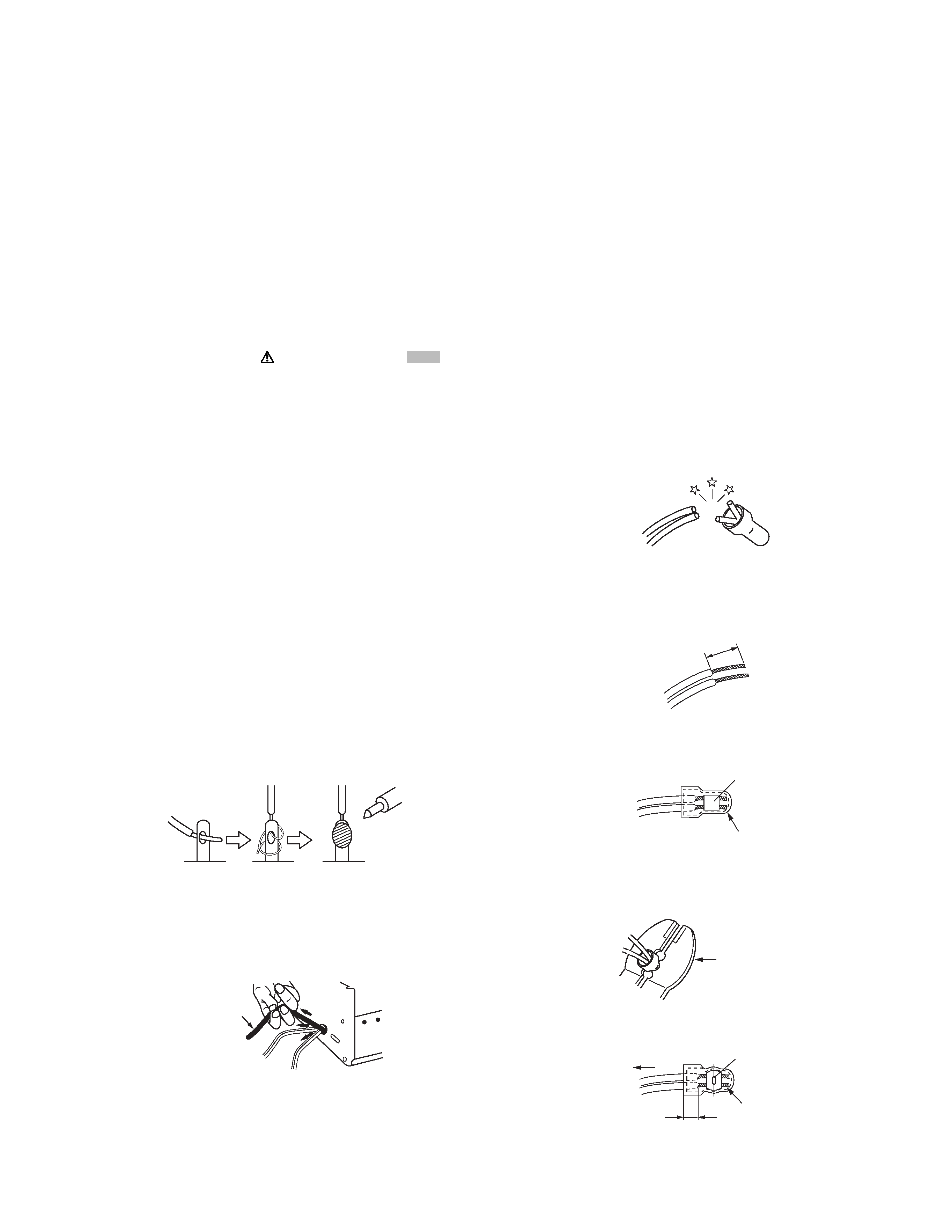
Fig.1-1-1
(7) Observe that wires do not contact heat producing parts
(heatsinks, oxide metal film resistors, fusible resistors, etc.)
(8) Check that replaced wires do not contact sharp edged or
pointed parts.
(9) When a power cord has been replaced, check that 10-15
kg of force in any direction will not loosen it.
Fig.1-1-2
(10) Also check areas surrounding repaired locations.
(11) Products using cathode ray tubes (CRTs)In regard to such
products, the cathode ray tubes themselves, the high
voltage circuits, and related circuits are specified for
compliance with recognized codes pertaining to X-ray
emission. Consequently, when servicing these products,
replace the cathode ray tubes and other parts with only the
specified parts. Under no circumstances attempt to modify
these circuits.Unauthorized modification can increase the
high voltage value and cause X-ray emission from the
cathode ray tube.
(12) Crimp type wire connectorIn such cases as when replacing
the power transformer in sets where the connections
between the power cord and power trans former primary
lead wires are performed using crimp type connectors, if
replacing the connectors is unavoidable, in order to prevent
safety hazards, perform carefully and precisely according
to the following steps.
· Connector part number :E03830-001
· Required tool : Connector crimping tool of the proper
type which will not damage insulated parts.
· Replacement procedure
a) Remove the old connector by cutting the wires at a
point close to the connector.Important : Do not
reuse a connector (discard it).
Fig.1-1-3
b) Strip about 15 mm of the insulation from the ends
of the wires. If the wires are stranded, twist the
strands to avoid frayed conductors.
Fig.1-1-4
c) Align the lengths of the wires to be connected.
Insert the wires fully into the connector.
Fig.1-1-5
d) As shown in Fig.1-1-6, use the crimping tool to crimp
the metal sleeve at the center position. Be sure to
crimp fully to the complete closure of the tool.
Fig.1-1-6
e) Check the four points noted in Fig.1-1-7.
Fig.1-1-7
Power cord
cut close to connector
15 mm
Connector
Metal sleeve
1.2
5
2.0
5.5
Crimping tool
Not easily pulled free
Crimped at approx. center
of metal sleeve
Conductors extended
Wire insulation recessed
more than 4 mm
1-4 (No.YF059)
1.1.2 Safety Check after Servicing
Examine the area surrounding the repaired location for damage
or deterioration. Observe that screws, parts and wires have been
returned to original positions, Afterwards, perform the following
tests and confirm the specified values in order to verify
compliance with safety standards.
(1) Insulation resistance test
Confirm the specified insulation resistance or greater
between power cord plug prongs and externally exposed
parts of the set (RF terminals, antenna terminals, video and
audio input and output terminals, microphone jacks,
earphone jacks, etc.).See table 1 below.
(2) Dielectric strength test
Confirm specified dielectric strength or greater between
power cord plug prongs and exposed accessible parts of
the set (RF terminals, antenna terminals, video and audio
input and output terminals, microphone jacks, earphone
jacks, etc.). See Fig.1-1-11 below.
(3) Clearance distance
When replacing primary circuit components, confirm
specified clearance distance (d), (d') between soldered
terminals, and between terminals and surrounding metallic
parts. See Fig.1-1-11 below.
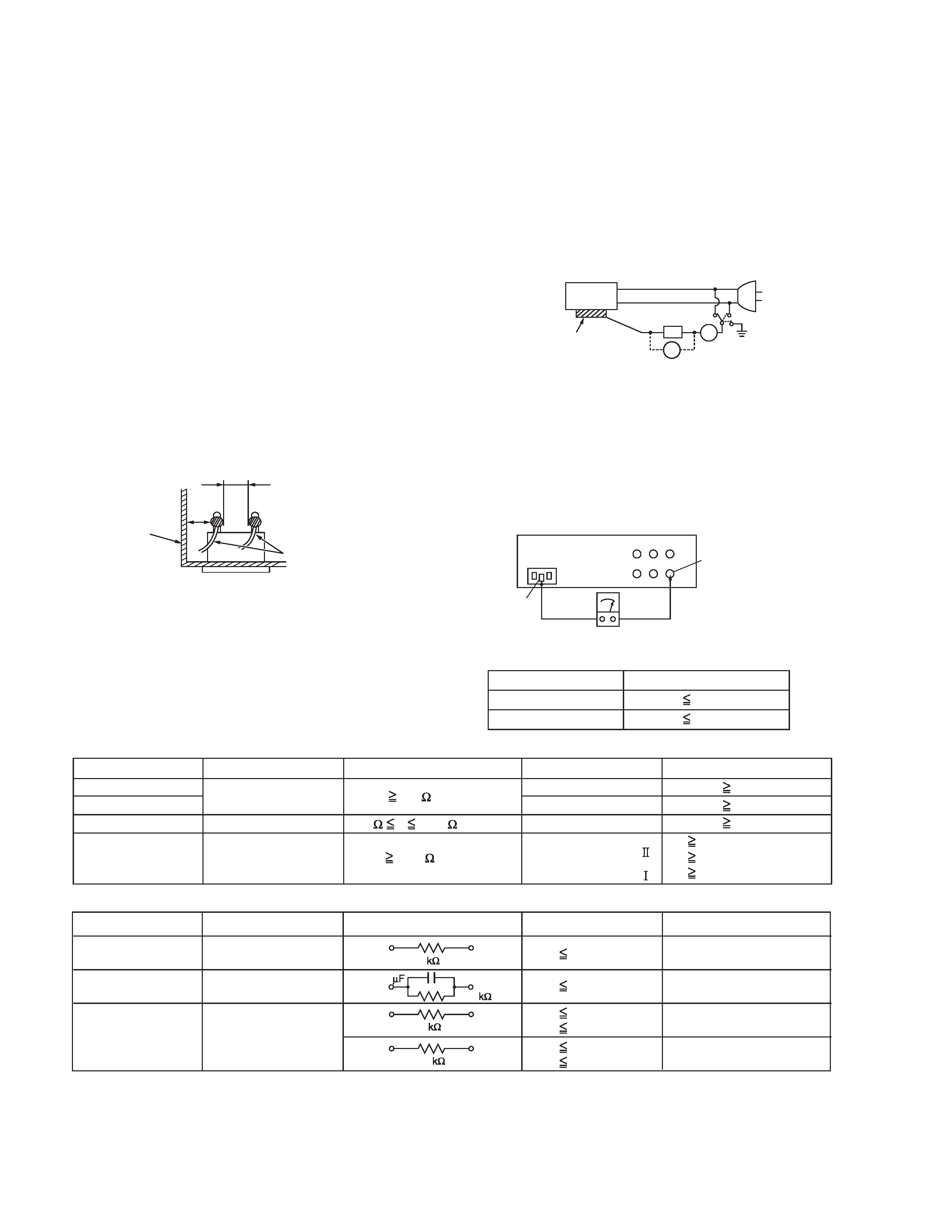
Fig.1-1-8
(4) Leakage current test
Confirm specified or lower leakage current between earth
ground/power cord plug prongs and externally exposed
accessible parts (RF terminals, antenna terminals, video
and audio input and output terminals, microphone jacks,
earphone jacks, etc.).
Measuring Method : (Power ON)Insert load Z between
earth ground/power cord plug prongs and externally
exposed accessible parts. Use an AC voltmeter to
measure across both terminals of load Z. See Fig.1-1-9
and following Fig.1-1-12.
Fig.1-1-9
(5) Grounding (Class 1 model only)
Confirm specified or lower grounding impedance between
earth pin in AC inlet and externally exposed accessible
parts (Video in, Video out, Audio in, Audio out or Fixing
screw etc.).Measuring Method:
Connect milli ohm meter between earth pin in AC inlet and
exposed accessible parts. See Fig.1-1-10 and grounding
specifications.
Fig.1-1-10
Fig.1-1-11
Fig.1-1-12
NOTE :
These tables are unofficial and for reference only. Be sure to confirm the precise values for your particular country and locality.
Chassis
Power cord
primary wire
d'
d
ab
c
V
A
Externally
exposed
accessible part
Z
Exposed accessible part
Grounding Specifications
AC inlet
Region
USA & Canada
Europe & Australia
Grounding Impedance (Z)
Z
0.1 ohm
Z
0.5 ohm
Earth pin
MIlli ohm meter
AC Line Voltage
Region
Japan
Europe & Australia
R 1 M /500 V DC
USA & Canada
1 M
R 12 M /500 V DC
R 10 M /500 V DC
Insulation Resistance (R)
Dielectric Strength
Clearance Distance (d), (d')
100 V
100 to 240 V
110 to 130 V
110 to 130 V
200 to 240 V
AC 1 kV 1 minute
AC 1.5 kV 1 minute
AC 1 kV 1 minute
(Class )
(Class )
AC 3 kV 1 minute
AC 1.5 kV 1 minute
d, d'
3 mm
d, d'
4 mm
d, d'
3.2 mm
d'
8 m m (Power cord)
d'
6 m m (Primary wire)
d
4 m m
AC Line Voltage
Region
Japan
Europe & Australia
USA & Canada
Load Z
Leakage Current (i)
a, b, c
100 V
110 to 130 V
110 to 130 V
220 to 240 V
i
1 mA rms
i
0.5 mA rms
i
0.7 mA peak
i
2 mA dc
i
0.7 mA peak
i
2 mA dc
Exposed accessible parts
Exposed accessible parts
Antenna earth terminals
Other terminals
1
1.5
2
50
0.15
(No.YF059)1-5
SECTION 2
SPECIFIC SERVICE INSTRUCTIONS
2.1
Handling Microdrives
Microdrives are used in GZ-MC100 and GZ-MC200. Although the appearance is different, a Microdrive is exactly the same as a hard
disc that is used in a PC. Therefore, unlike handling conventional tapes, caution must be paid in handling Microdrives.
The handling of Microdrives is explained in this section.
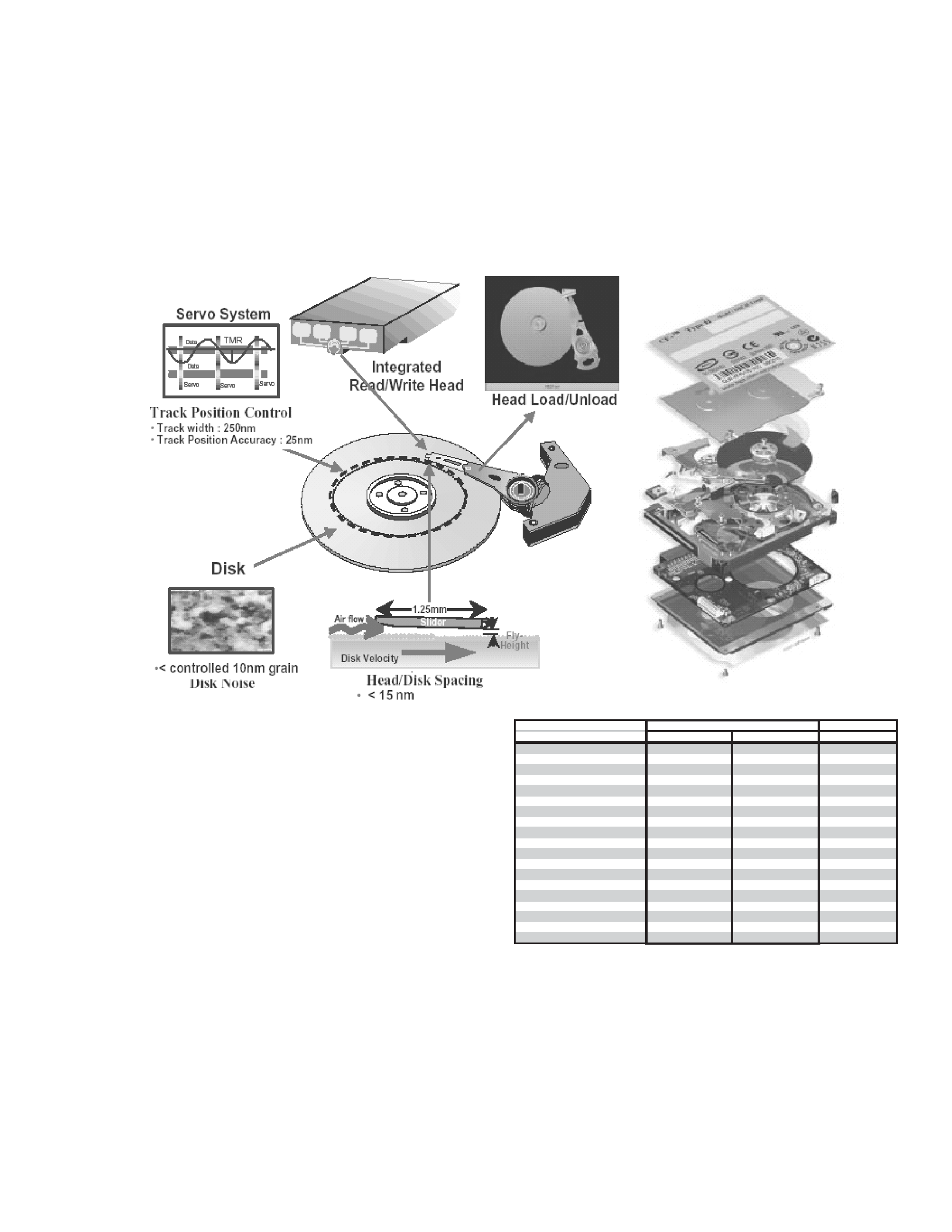
2.1.1 The structure of Microdrives
The detailed inside structure of Microdrives is not disclosed as it is treated as trade secrets. However, it is essential to have knowledge
of the structure of Microdrives in order to carry out service properly. Some information about Microdrives is given here.
A Microdrive is mainly consisted of the following parts.
· A magnetic recording disk that is coated with magnetic ma-
terial. (Disk)
· A reading/ writing head. (Head)
· A motor that turns the disk.
· A circuit board that is loaded with electrical circuit which con-
trols the motor, the head positioning, and input/ output of the
signal.
1 head type Microdrives use one side of the disk, and 2 head type
Microdrives use both sides of the disk with heads on each side
of the disk.The disk and the head do not contact and there is
certain space kept between them. The head reads the pre
recorded servo information to control the head itself. When the
head is not in access to the disk, it is kept in a shelter to avoid
damaging the disk with shocks from outside.
The difference between a 2GB Microdrive and a 4GB Microdrive
is only whether it has one head or two heads and there is no
difference in performance, as shown in the specification list. A
2.5 inch hard disk that is used in a note PC is shown as a
reference. As a 2.5 inch hard disk is bigger than a Microdrive, it
has more disks and heads resulting in more capacity. On the
contrary, it seems impossible to increase the disks for a
Microdrive because of size restriction. High capacity will be
achieved by improving the areal density and rotation speed of the
future products.
Shock tolerance during non-operation is remarkably high. Micro-
drives are designed to tolerate shock during non-operation as
they are removed or carried out more often than other hard disks.
However, Microdrives are vulnerable to falls and shocks just like
other precision instruments.
Microdrives are made in conformity with the standard of Com-
pactFlash Type II. The thickness of the drive is less than 5.5mm,
thus failures can occur by folding or twisting the disks. The stan-
dard for torsional stress is 6kg approx. and for flexing stress is
4kg approx. Be sure to carry Microdrives in protection cases on
the service sites, and strongly recommend the customers to do
so, too.
hard disk
2GB
4GB
80GB
Model name
Microdrive 3K4-2
Microdrive 3K4-4
Travelstar 4K80-80
Model number
HMS360402D5CF00
HMS360404D5CF00
HTS428080F9AT00
Capacity
2 GB
4 GB
80 GB
Interface
CompactFlash Type
CompactFlash Type
ATA ATA-6
Form factor
1inch
1inch
2.5inch
System type
Consumer electronics
Consumer electronics
Laptop
Cache buffer
128 KB
128 KB
8 MB
Disks / Heads
1/1
1/2
2/4
Rotational speed (RPM)
3,600 (RPM)
3,600 (RPM)
4,200 (RPM)
Media transfer rate
97.9 Mb/sec max
97.9 Mb/sec max
351 Mb/sec max
Interface transfer rate
33 MB/sec max
33 MB/sec max
100 MB/sec max
Average seek (ms)
12 (ms)
12 (ms)
13 (ms)
Average latency (ms)
8.33 (ms)
8.33 (ms)
7.1 (ms)
Areal density
56.5 Gb/sq. inch
56.5 Gb/sq. inch
68.5 Gb/sq. inch
Typical idle acoustic (Bels)
2.4B
Operating shock (G)
200 G (2ms)
200 G (2ms)
250 (2ms)
Non-operating shock (G)
2000 G (1ms)
2000 G (1ms)
800 (1ms)
Operating ambient temperature (
)0
70 (
)0
70 (
)5
55 (
)
Non-operating ambient temperature ( )
-40
70 (
)
-40
70 (
)
-40
70 (
)
Microdrive
