SPECIFICATIONS (The specifications shown pertain specifically to the model GR-DVM50UM)
VICTOR COMPANY OF JAPAN, LIMITED
VIDEO DIVISION
Printed in Japan
S40894
SPECIFICATIONS
Camcorder
General
Power supply
: DC 6.3 V
(Using the AC Power
Adapter/Charger)
DC 7.2 V
(Using battery pack)
Power consumption
LCD monitor off, viewfinder on
: Approx. 4.5 W
LCD monitor on, viewfinder off
: Approx. 5.4 W
Format
: DV Format (SD mode)
Signal format
: NTSC Standard
Video signal recording format
: Digital Component Recording
Cassette
: Mini DV Cassette
Tape Speed
: SP: 18.8 mm/s
LP: 12.5 mm/s
Maximum recording time
: SP: 60 min.
LP: 90 min. (using M-DV60ME cassette)
Pickup
: 1/4" CCD
Lens
: F 1.8, f = 3.6 to 36 mm, 10:1 Power Zoom
Lens
Filter diameter
: ø27 mm
LCD monitor
: 2.5" diagonally measured, LCD panel/TFT
active matrix system
Viewfinder
: Electronic viewfinder with 0.55" color
LCD
Speaker
: Monaural
Operating temperature
:0
°C to 40°C (32°F to 104°F)
Operating humidity
: 35% to 80%
Storage temperature
: 20
°C to 50°C (4°F to 122°F)
Dimensions
: 48 (W) x 119 (H) x 89 (D) mm (1-15/16" x
4-11/16" x 3-9/16")
(with the LCD monitor closed and the
viewfinder pushed back in)
Weight
: Approx. 420 g (0.93 lbs) (without grip
strap, cassette and battery)
Approx. 505 g (1.2 lbs) (incl. grip strap,
cassette and battery)
Connectors
Video output
: 1 Vp-p, 75
unbalanced, analog output
(via AV OUT connector)
Audio output
: 8 dBs, 1 k
analog output, stereo (via AV
OUT connector)
Headphone output
: ø3.5 mm, stereo (via AV OUT connector)
DV input/output
: 4-pin, IEEE1394 compliant
AC Power Adapter/Charger AA-V50EN
Power requirement
: AC 110 V to 240 V`, 50/60 Hz
Power consumption
: 20 W
Output
Charge
: DC 7.2 V
, 0.63 A
VTR
: DC 6.3 V
, 1.8 A
Dimensions
: 122 (W) x 39 (H) x 92 (D) mm (4-13/16" x
1-9/16" x 3-5/8")
Weight
: Approx. 320 g (0.71 lbs)
Specifications shown are for SP mode unless otherwise indicated. E & O.E.
Design and specifications subject to change without notice.
Docking Station
General
Dimensions
: 115 mm (W) x 31 mm (H) x 55
mm (D) (4-9/16" x 1-1/4" x 2-3/
16")
Weight
: Approx. 90 g (0.2 lbs)
Connectors
S-Video
: Y: 1Vp-p, 75
, analog output
C: 0.29 Vp-p, 75
, analog output
Video
: 1Vp-p, 75
, analog output
Audio
: 8 dBs, 1 k
, analog output
JLIP
: ø3.5 mm, 4-pole, mini-head jack
(compatible with RC-5325 plug)
Editing
: ø3.5 mm diameter, 2-pole
PC
: ø2.5 mm, 3-pole
External microphone input
: 68 dBs, high impedance
unbalanced with ø3.5 mm (stereo)
E & O.E. Design and specifications subject to change without
notice.
DIGITAL VIDEO CAMERA
GR-DVM50UM
No. 86587
September 2000
COPYRIGHT
© 2000 VICTOR COMPANY OF JAPAN, LTD.
Regarding service information other than these sections, refer to the GR-DVM50U service manual (No. 86480).
Also, be sure to note important safety precautions provided in the service manual.
This service manual is made from all recycled paper.
(AUDINAC KIT)
AC POWER ADAPTER CHARGER
AA-V50U
AA-V50EN
S CABLE,S-VIDEO CABLE
Optional
Provided
A/V RCA CABLE
Optional
Provided
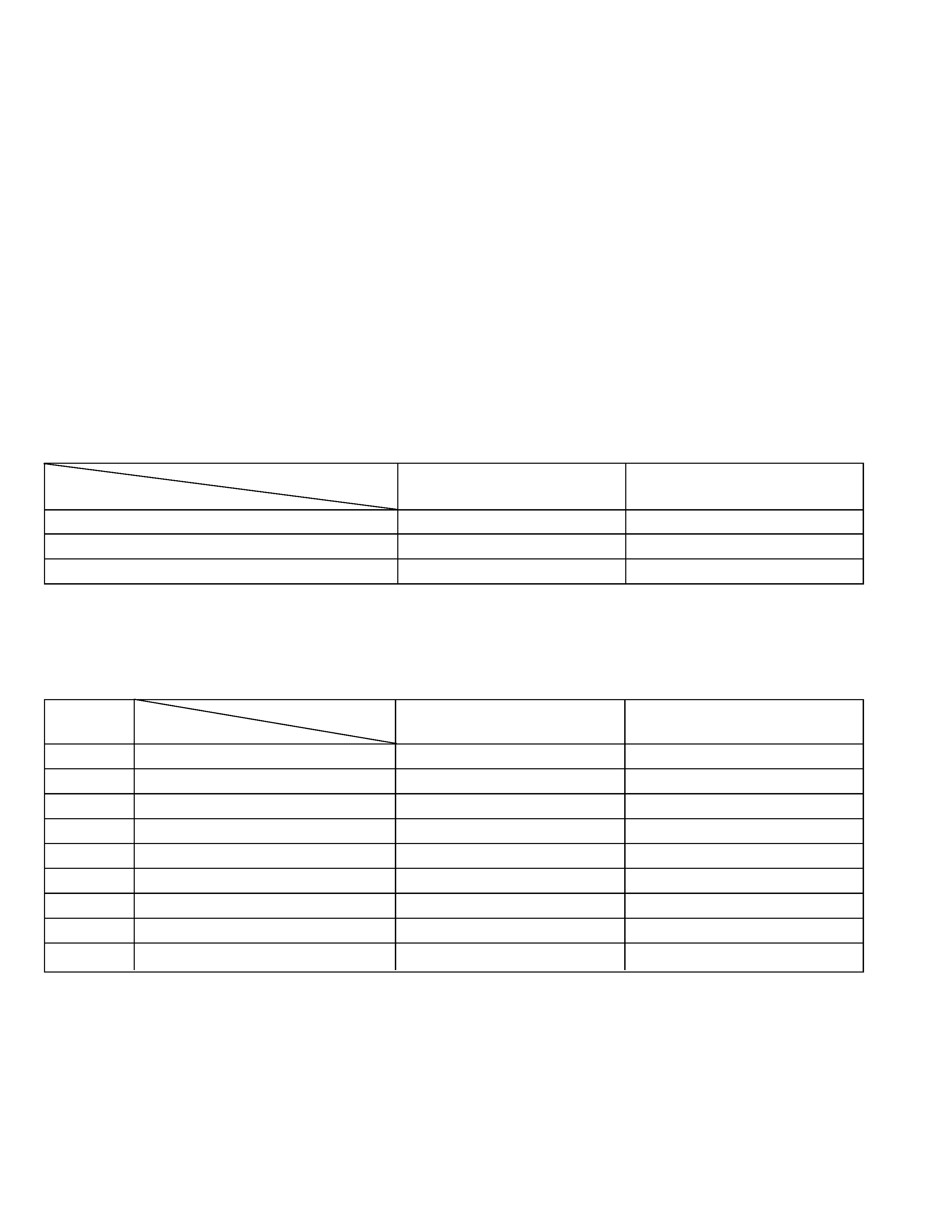
The following table indicate main different points between models GR-DVM50U and GR-DVM50UM.
GR-DVM50U
GR-DVM50UM
MODEL
ITEM
The following table indicate different parts number between models GR-DVM50U and GR-DVM50UM.
PACKING AND ACCESSORY ASSEMBLY <M1> Note: As for IB (INSTRUCTION),refer to sec.5.
TABLE OF CONTENTS
DIFFERENT TABLE ..................................................................................................................................................................... 1 to 3
4. CHARTS AND DIAGRAMS
4.1 VF MAIN SCHEMATIC DIAGRAM ..................................................................................................................................... 4-1
4.2 A/HP SEL SCHEMATIC DIAGRAM .................................................................................................................................... 4-2
4.3 DC/DC SCHEMATIC DIAGRAM ........................................................................................................................................ 4-3
4.4 DV MAIN SCHEMATIC DIAGRAM ..................................................................................................................................... 4-4
4.5 MAIN CIRCUIT BOARD ..................................................................................................................................................... 4-6
4.6 W/B AND JACK CIRCUIT BOARDS ................................................................................................................................ 4-10
5. PARTS LIST
5.1 PACKING AND ACCESSORY ASSEMBLY <M1> .............................................................................................................. 5-1
5.2 FINAL ASSEMBLY <M2> ................................................................................................................................................... 5-3
6. AC POWER ADAPTER CHARGER
6.1 CABINET ASSEMBLY <MA> ............................................................................................................................................. 6-1
6.2 CIRCUIT BOARD ............................................................................................................................................................... 6-2
6.3 SCHEMATIC DIAGRAM ..................................................................................................................................................... 6-3
6.4 ELECTRICAL PARTS LIST ................................................................................................................................................ 6-5
1
1
PACKING CASE
LY31257-001B
8
CD ROM ASSY
*
LY31133-005B
LY31133-005D
25
WARRANTY INF.
BT-51005-3
31
REGIST.CARD
BT-51020-1
32
MINI DV TAPE
Not used
Used
33
A/V RCA CABLE
YQ31953A
34
CORE FILTER
QQR0919-002
35
S CABLE, S-VIDEO CABLE
QAM0004-004
36
CORE FILTER
QQR0918-002
MODEL
ITEM
REF. No.
GR-DVM50U
GR-DVM50UM
FINAL ASSEMBLY <M2> Refer to sec.5.
Note:
Mark is not used.
Mark * reference model was also changed.
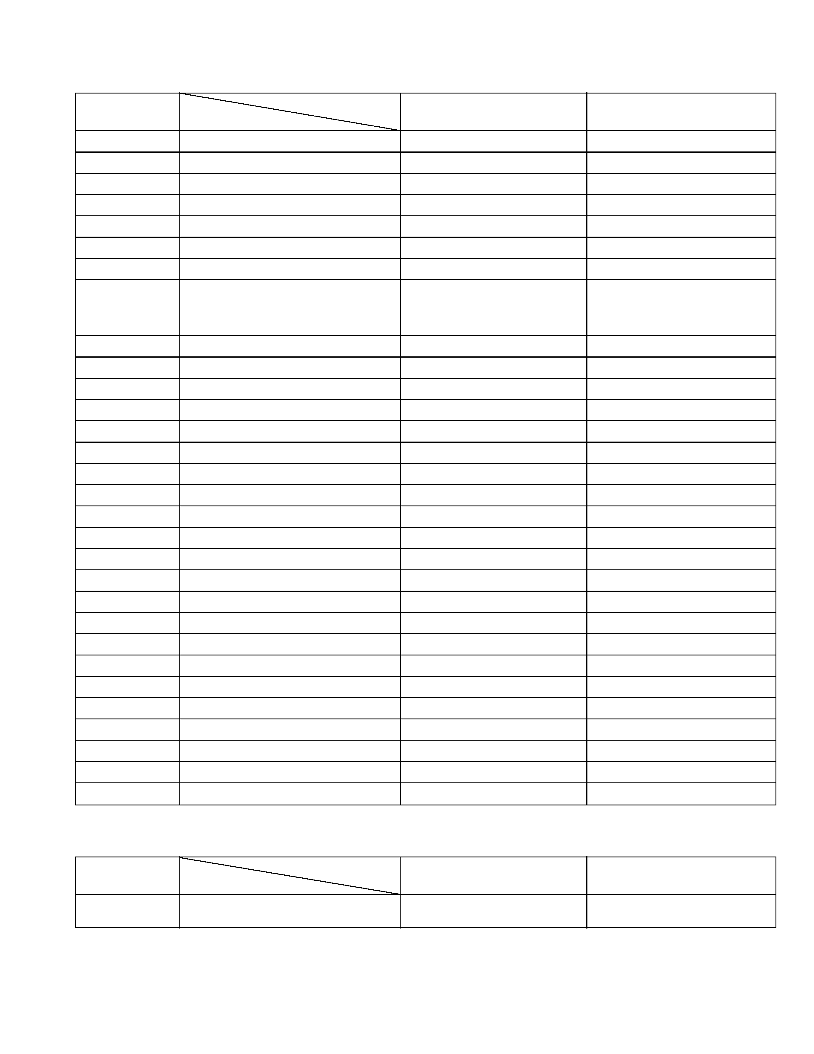
MAIN BOARD ASSEMBLY <01>
PW
MAIN BOARD ASSY
*
YB10245F
YB10258B-02
IC3004
IC
*
TK11216BMC
TK11218BMC
Q2703,Q2704
TRANSISTOR
*
2SC4617/QR/-X
2SC5585
Q2761
TRANSISTOR
*
DTC144EE
Q2762 to Q2764
TRANSISTOR
*
DTA124EE
Q2765
TRANSISTOR
*
DTC144EE
R1034
MG RESISTOR
*
NASA6AJ-0R0W
R2112,R2113
R2408,R2409
MG RESISTOR
*
NASA6AJ-0R0W
R2420,R2426
R2706
MG RESISTOR
*
NRSA6AJ-104W
NRSA6AJ-153W
R3048
MG RESISTOR
*
NRSA6AJ-0R0W
R3221
MG RESISTOR
*
NRSA6AJ-101W
NASA6AJ-820W
R3223
CMF RESISTOR
*
NRVA6AD-242W
NRVA6AD-222W
R3301
MG RESISTOR
*
NASA6AJ-391W
R6101
CMF RESISTOR
*
NRVA6AD-822W
NRVA6AD-133W
R6152,R6154
MG RESISTOR
*
NRSA6AJ-0R0W
R7623
MG RESISTOR
*
NRSA6AJ-0R0W
C1006
CAPACITOR
*
NDCA1HJ-150W
NDCA1HJ-180W
C1013
CAPACITOR
*
NDCA1HJ-100W
NDCA1HJ-130W
C2212
T CAPACITOR
*
NBE41AM-106X
NBE90JM-106X
C2766
T CAPACITOR
*
NBE90JM-106X
C3015
T CAPACITOR
*
NBG40GM-226X
C3049
CAPACITOR
*
NCFA1AZ-104W
NCB31CK-104X
C3051
MG RESISTOR
*
NRSA6AJ-331W
C4338
CAPACITOR
*
NCBA1HK-102W
C6105
CAPACITOR
*
NCB21AK-225X
C6128
CAPACITOR
*
NDCA1HJ-6R0W
L1005
COIL
*
NQL184J-390X
NQL024J-330X
L3001
FERRITE BEAD
*
NQR0305-001X
L3103
CHOKE COIL
*
NQR0276-001X
X1002
CRYSTAL RESONATOR
*
NAX0267-001X
NAX0325-001X
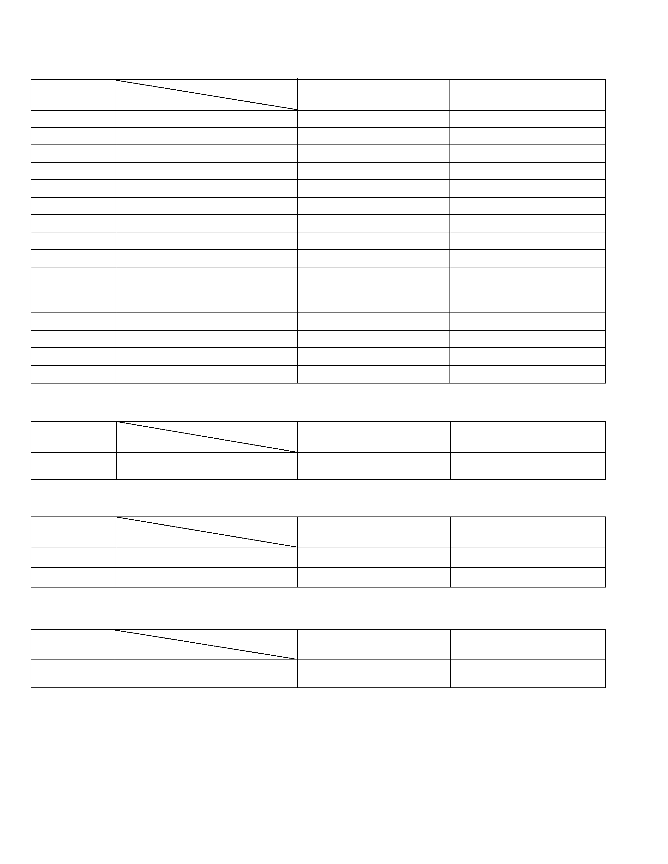
MODEL
ITEM
REF. No.
GR-DVM50U
GR-DVM50UM
Note:
Mark is not used.
Mark * reference model was also changed.
2
SUB BOARD ASSEMBLY
PW
SUB BOARD ASSY
*
YB20858A
MODEL
ITEM
REF. No.
GR-DVM50U
GR-DVM50UM
3
MDA BOARD ASSEMBLY <02>
PW1
MDA BOARD ASSY
*
YB10246B1
YB10246B1-03
IC4807
IC
*
TC7W66FK
Q4802
TRANSISTOR
*
2SC4617/RS/-X
Q4803
TRANSISTOR
*
DTC144EE
Q4804
TRANSISTOR
*
DTA144EE
R4827
MG RESISTOR
*
NRSA6AJ-0R0W
R4829
MG RESISTOR
*
NRSA6AJ-0R0W
R4831
MG RESISTOR
*
NRSA6AJ-472W
R4832
MG RESISTOR
*
NRSA6AJ-103W
R4837
R4839,R4840
MG RESISTOR
*
NRSA6AJ-0R0W
R4846
R4849
MG RESISTOR
*
NRSA6AJ-0R0W
C4864
T CAPACITOR
*
NBE90JM-106X
C4865
CAPACITOR
*
NCFA1AZ-104W
L4853
COIL
*
NQL302N-100X
MODEL
ITEM
REF. No.
GR-DVM50U
GR-DVM50UM
MONITOR BOARD ASSEMBLY <04>
PW
MONITOR BOARD ASSY
*
YB10250B
YB10250B-01
MODEL
ITEM
REF. No.
GR-DVM50U
GR-DVM50UM
W/B BOARD ASSEMBLY <08>
PW2
W/B BOARD ASSY
*
YB10248A2-03
YB10248A2-04
WR1
E-SI C WIRE C-F
*
WJM0077-001A
WJM0077-001B
MODEL
ITEM
REF. No.
GR-DVM50U
GR-DVM50UM
JACK BOARD ASSEMBLY <09>
PW1
JACK BOARD ASSY
*
YB10248C1
YB10248C1-01
MODEL
ITEM
REF. No.
GR-DVM50U
GR-DVM50UM
Note:
Mark is not used.
Mark * reference model was also changed.
6-1
SECTION 6
AC POWER ADAPTER CHARGER (AA-V50EN)
SAFETY PRECAUTION
Parts identified by the
! symbol are critical for safety. Replace only with specified part numbers.
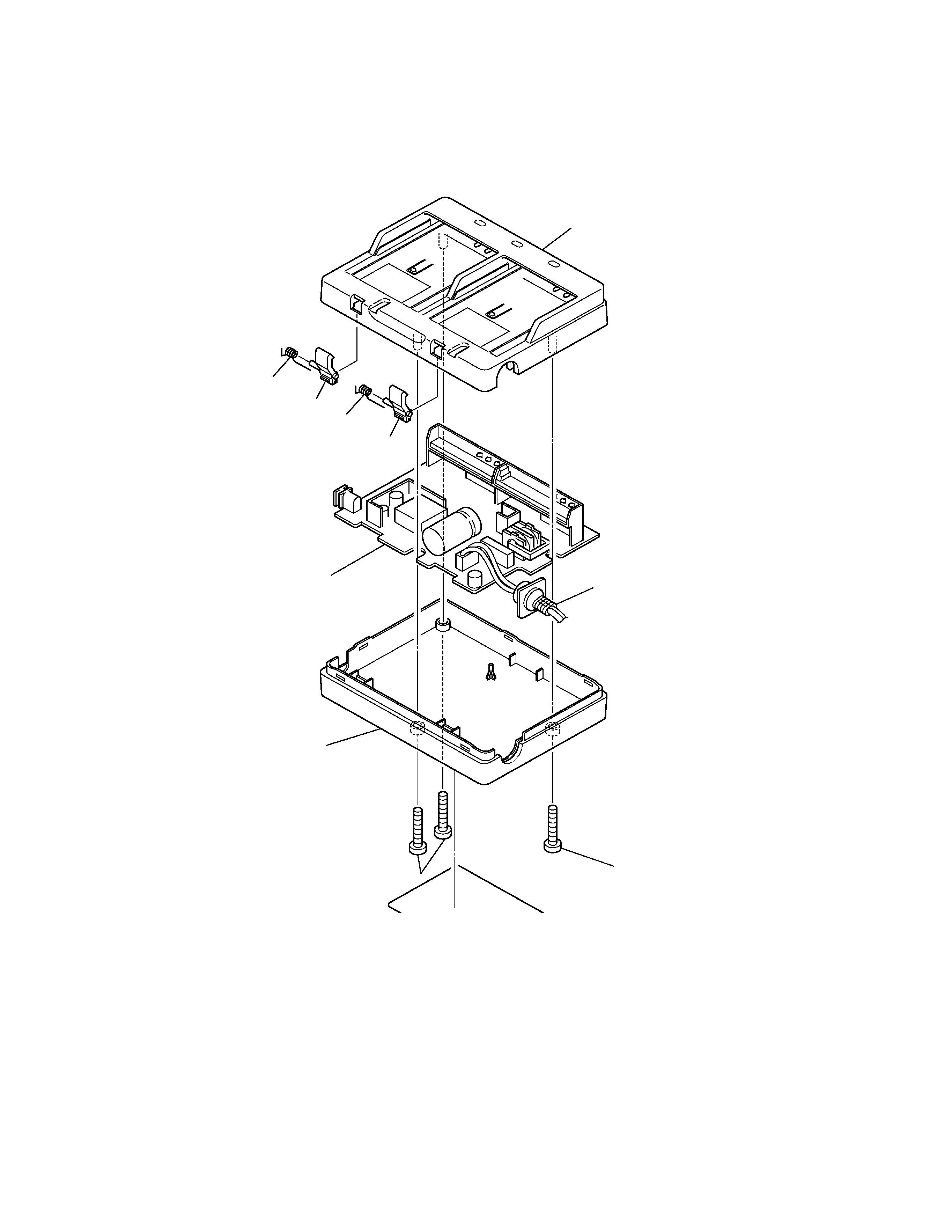
6.1 CABINET ASSEMBLY <MA>
#
!REF No. PART No.
PART NAME, DESCRIPTION
-----------------------
------------------------------
----------------------------------------------------------------------------
CABINET ASSEMBLY
<MA>
1
PTY20450-012
UPPER CASE ASSY
2
PTY20450-017
LOWER CASE ASSY
! 3
PTY20483-035
AC POWER CORD
4
PTY20450-050
LOCK LEVER,X2
5
PTY20450-051
LOCK SPRING,X2
6
PTY20292-165
SCREW,X3
6
2
4
5
4
6
3
1
MAIN <91>
5