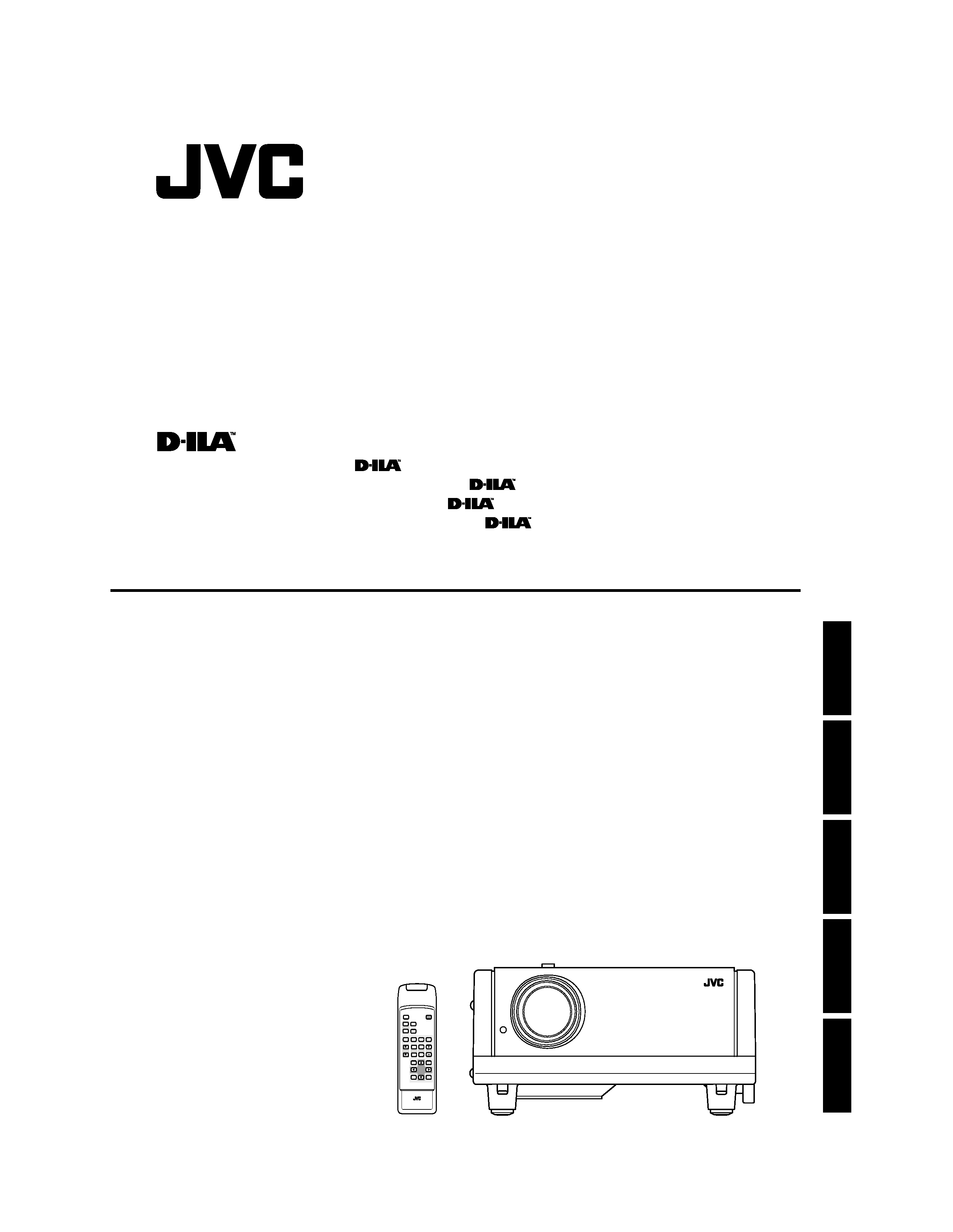
DLA-G150HTE
OPERATING INSTRUCTIONS
PROJECTOR
BEDIENUNGSANLEITUNG :
PROJEKTOR
MANUEL D'INSTRUCTIONS : PROJECTEUR
MANUALE D'ISTRUZIONI : PROIETTORE
MANUAL DE INSTRUCCIONES : PROYECTOR
DLA-G150HTE INSTRUCTIONS
QUICK
ALIGN.
PC1
PC2
Y/C
VIDEO
HIDE
PRESET
ENTER
EXIT
MENU
FREEZE
SCREEN
OPERATE
DIGITAL
ZOOM
ZOOM FOCUS
W
W
S
T
W
T
RM-M150 REMOTE CONTROL UNIT
SCREEN
KEYSTONE
W
S
ENGLISH
DEUTSH
FRANÇAIS
ITALIANO
ESPAÑOL
Jan. 2002 No. 51847

DLA-G150HTE
1-2
No.51847
3
ENGLISH
F
RANÇAIS
POWER CONNECTION
(United Kingdom only)
WARNING
Do not cut off the main plug from this equipment.
If the plug fitted is not suitable for the power points in your
home or the cable is too short to reach a power point, then
obtain an appropriate safety approved extension lead or
adapter or consult your dealer.
If nonetheless the mains plug is cut off, remove the fuse and
dispose of the plug immediately, to avoid a possible shock
hazard by inadvertent connection to the main supply.
If a new main plug has to be fitted, then follow the instruction
given below:
WARNING:
THIS APPARATUS MUST BE EARTHED.
IMPORTANT:
The wires in the mains lead on this product are coloured in
accordance with the following cord:
Green-and-yellow:
Earth
Blue:
Neutral
Brown:
Live
As these colours may not correspond with the coloured
making identifying the terminals in your plug, proceed as
follows:
The wire which is coloured green-and-yellow must be
connected to the terminal which is marked
with the letter
E or the safety earth or coloured green or green-and-yellow.
The wire which is coloured blue must be connected to the
terminal which is marked with the letter N or coloured black.
The wire which is coloured brown must be connected to the
terminal which is marked with the letter L or coloured red.
When replacing the fuse, be sure to use only a correctly
rated approved type, re-fit the fuse cover.
IF IN DOUBT ---- CONSULT A COMPETENT
ELECTRICIAN.
How To Replace The Fuse
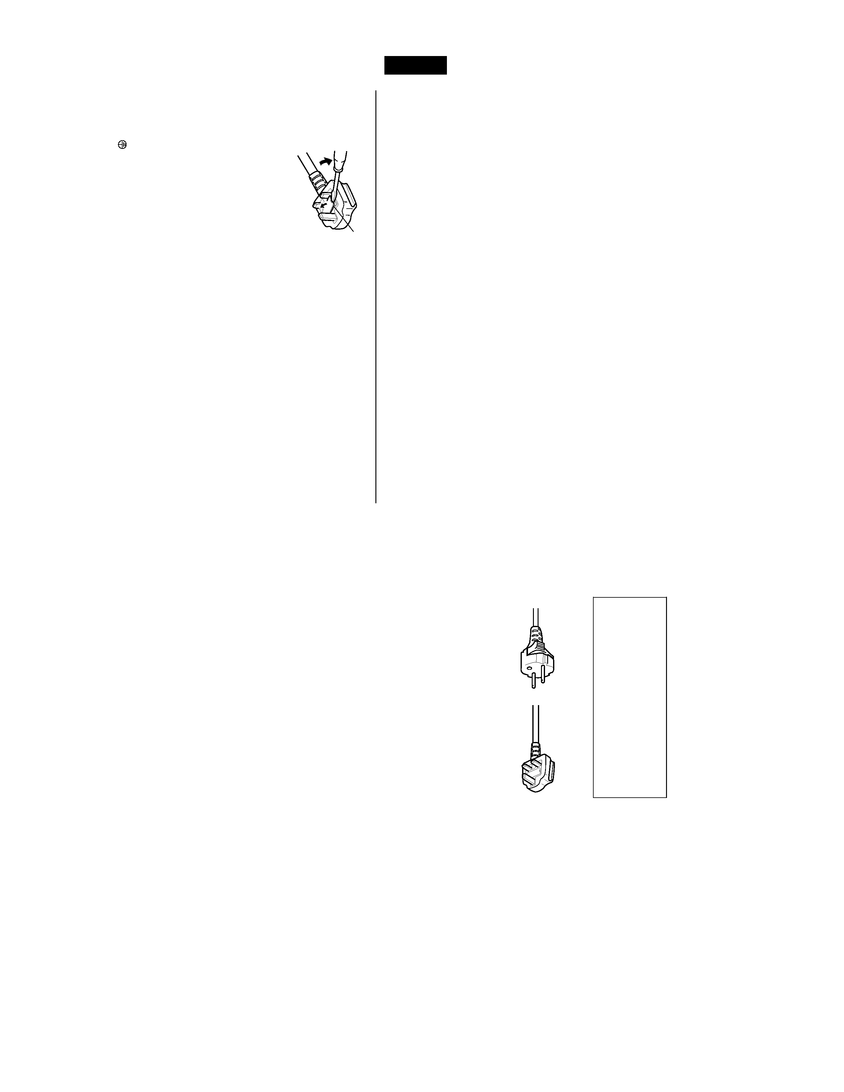
Open the fuse compartment with the blade screwdriver, and
replace the fuse.
(* An example is shown in the illustration below.)
Fuse
2
This product should be operated only with the type of
power source indicated on the label. If you are not sure
of the type of power supply to your home, consult your
product dealer or local power company.
This product is equipped with a three-wire plug. This
plug will fit only into a grounded power outlet. If you are
unable to insert the plug into the outlet, contact your
electrician to install the proper outlet. Do not defeat the
safety purpose of the grounded plug.
Power-supply cords should be routed so that they are not
likely to be walked on or pinched by items placed upon or
against them. Pay particular attention to cords at doors,
plugs, receptacles, and the point where they exit from the
product.
For added protection of this product during a lightning
storm, or when it is left unattended and unused for long
periods of time, unplug it from the wall outlet and
disconnect the cable system. This will prevent damage
to the product due to lightning and power line surges.
Do not overload wall outlets, extension cords, or
convenience receptacles on other equipment as this can
result in a risk of fire or electric shock.
Never push objects of any kind into this product through
openings as they may touch dangerous voltage points or
short out parts that could result in a fire or electric shock.
Never spill liquid of any kind on the product.
Do not attempt to service this product yourself as
opening or removing covers may expose you to
dangerous voltages and other hazards. Refer all service
to qualified service personnel.
Unplug this product from the wall outlet and refer service
to qualified service personnel under the following
conditions:
a) When the power supply cord or plug is damaged.
b) If liquid has been spilled, or objects have fallen on the
product.
c) If the product has been exposed to rain or water.
d) If the product does not operate normally by following
the operating instructions. Adjust only those controls
that are covered by the Operation Manual, as an
improper adjustment of controls may result in damage
and will often require extensive work by a qualified
technician to restore the product to normal operation.
e) If the product has been dropped or damaged in any
way.
f ) When the product exhibits a distinct change in
performance this indicates a need for service.
When replacement parts are required, be sure the
service technician has used replacement parts specified
by the manufacturer or with same characteristics as the
original part. Unauthorized substitutions may result in
fire, electric shock, or other hazards.
Upon completion of any service or repairs to this product,
ask the service technician to perform safety checks to
determine that the product is in proper operating
condition.
The product should be placed more than one foot away
from heat sources such as radiators, heat registers,
stoves, and other products (including amplifiers) that
produce heat.
When connecting other products such as VCR's, and
personal computers, you should turn off the power of this
product for protection against electric shock.
Do not place combustibles behind the cooling fan. For
example, cloth, paper, matches, aerosol cans or gas
lighters that present special hazards when over heated.
Do not look into the projection lens while the illumination
lamp is turned on. Exposure of your eyes to the strong
light can result in impaired eyesight.
Do not look into the inside of this unit through vents
(ventilation holes), etc. Do not look at the illumination
lamp directly by opening the cabinet while the
illumination lamp is turned on. The illumination lamp also
contains ultraviolet rays and the light is so powerful that
your eyesight can be impaired.
Do not drop, hit, or damage the light-source lamp (lamp
unit) in any way. It may cause the light-source lamp to
break and lead to injuries. Do not use a damaged light-
source lamp. If the light-source lamp is broken, ask your
dealer to repair it. Fragments from a broken light-source
lamp may cause injures.
Xenon gas is enclosed with high pressure inside the light-
source lamp (lamp unit) of this projector. If you drop or
impart a shock to the lamp, or discard it as is, there is the
possibility of explosion, leading to personal injury. Use
special care when handling the lamp. For any unclear
points, consult your product dealer.
Do not "ceiling-mount" the projector to a place which
tends to vibrate; otherwise, the attaching fixture of the
projector could be broken by the vibration, possibly
causing it to fall or overturn, which could lead to personal
injury.
Use only the accessory cord designed for this product to
prevent shock.
The power supply voltage rating of this product is
AC 200 V - AC 240 V, the power cord attached conforms
to the following power supply voltage. Use only the
power cord designated by our dealer to ensure Safety
and EMC.
When it is used by other power supply voltage, power
cable must be changed.
Ensure that the power cable used for the projector is the
correct type for the AC outlet in your country.
Consult your product dealer.
* DO NOT allow any unqualified person to
install the unit.
Be sure to ask your dealer to install the unit (eg.
attaching it to the ceilling) since special technical
knowledge and skills are required for installation.
If installation is performed by an unqualified person, it
may cause personal injury or electrical shock.
Power cord
For United Kingdom
For European
continent countries

DLA-G150HTE
1-3
No.51847
5
ENGLISH
DEUTSH
FRAN
ÇAIS
ITALIANO
ESPAÑOL
Accessories
The following accessories are included with this projector. Check for them; if any item is missing, please
contact your dealer.
I
I
I
I Remote control unit (RM-M150G)
I
I
I
I AA/R6-size dry cell battery (××××2)
(for checking operation)
I
I
I
I Power cord
[approx. 8.2 ft (approx. 2.5 m)
(for European continental countries)
(for United Kingdom)
I
I
I
I Ferrite core (××××2)
I
I
I
I Personal computer connection cable
[approx. 6.56 ft (approx. 2 m)]
(D-sub, 3-row 15 pin)
I
I
I
I Video cable
[approx. 6.56 ft (approx. 2 m)]
I
I
I
I Conversion adapter for Mac
(for Macintosh)
I
I
I
I BNC-RCA Conversion plug
4
Contents
SAFETY PRECAUTIONS ................. 1
Contents ........................................... 4
Accessories ..................................... 5
Controls and Features .................... 6
Front Side / Top Surface / Right Side .....................6
Left-hand Side / Rear Side......................................7
Bottom Surface .......................................................8
Control Panel on the Projector ................................9
Connector Panel ...................................................11
Remote Control Unit..............................................12
Installing Batteries.................................................14
Precautions for using batteries..............................14
Installing the Projector.................. 15
Precautions for Installation....................................15
Adjusting the Inclination of the Projector...............16
Installing the Projector against the Screen............17
Projection Distance and Screen Size....................18
Relationship between Projector Distances and
Projector Screen Size ...........................................19
Effective Range and Distance of the
Remote Control Unit..............................................20
Setting the Position Selecting Screw for Ceiling
Mounting ...............................................................21
When installing (adjusting/setting) the unit............21
Connecting to Various Devices.... 22
Signals that Can Be Input to the Projector ............22
Connecting to Video Devices ................................24
Connecting to Hi-Vision Devices/DVD Players .....25
Connecting to Other Devices ................................26
Connecting to Devices which Control the
Projector................................................................27
Connecting to Computer Devices .........................28
How to attach the ferrite core ................................29
Connecting the Power Cord ..................................30
Removing the Lens Cap........................................30
Basic Operations ........................... 31
1. Turning on the Power........................................31
2. Select the Input source to be Projected ............32
3. Adjust the Screen Size (Zooming) ....................33
4. Adjust Focus .....................................................33
5. Setting the Screen Aspect Ratio .......................33
Turning off Image (HIDE) ......................................34
Removing the Trapezoidal Distortion of the
Image ....................................................................34
Quick Alignment Function (QUICK ALIGN.)..........35
Displaying a Still Picture (FREEZE) ......................36
Zooming a Part of the Image
(DIGITAL ZOOM T/W) ..........................................36
Menu Operations ........................... 37
Basic Menu Operation...........................................42
Changing the Color System
(Video Menu Mode Only) ......................................44
Changing the Language Display ...........................45
Changing the Screen aspect ratio/HDTV format
(Video Menu Mode Only) ......................................45
Adjusting Tracking/Phase .....................................46
Setting for Watching Image Software
(Video Menu Mode Only) ..................................... 47
Adjusting Picture Quality ...................................... 48
Adjusting Color temperature................................. 49
Adjusting the Video Screen/Menu Position .......... 50
Changing the Image Tone/Aspect Ratio
(Video Menu Mode Only) ..................................... 51
Changing the Image Size - Resize Function
(PC Menu Mode Only).......................................... 52
Changing the Clamp pulse position
(PC Menu Mode Only).......................................... 52
Setting and Adjusting Other Functions
(OPTIONS)........................................................... 53
Getting Information............................................... 55
Replacing the Fuse ........................ 56
Replacing the Light-Source
Lamp ............................................... 57
Cleaning and Replacing the
Filter Cover ..................................... 61
Troubleshooting............................. 62
Warning Indication......................... 64
Warning Messages ........................ 65
Specifications................................. 67
Outside dimensions.............................................. 69
Pin assignment (Specifications for terminals) ...... 70
RS-232C external control .............. 71

DLA-G150HTE
1-4
No.51847
6
Controls and Features
Front Side / Top Surface / Right Side
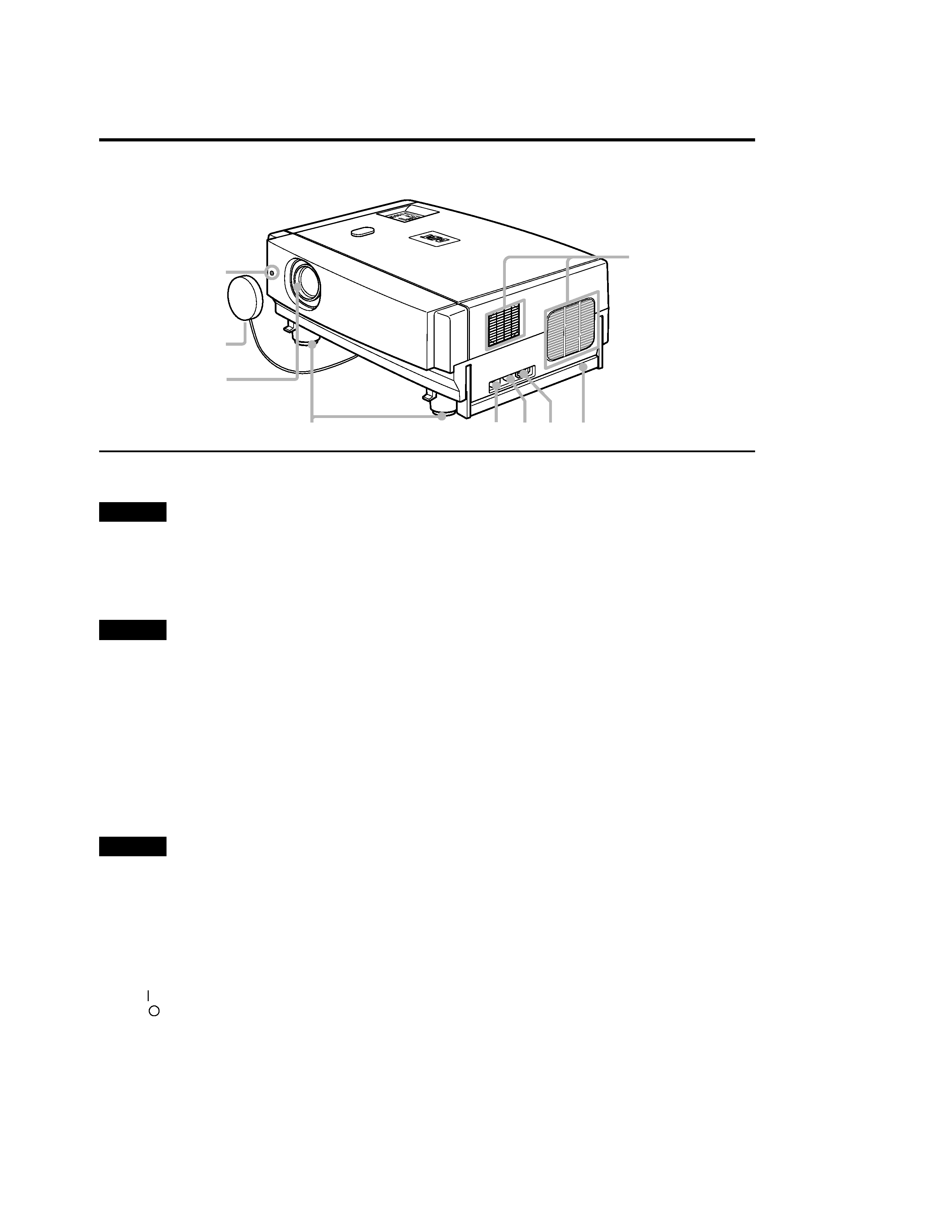
1 Exhaust vents
Vents for cooling fans through which warm air comes out.
CAUTION
· Do not block the exhaust vents, or heat will build up inside,
possibly causing a fire. Also, do not touch the vents, or this
could give you a low-temperature burn.
2 Carrying handle
Raise this handle when carrying the projector.
CAUTIONS
· When carrying the projector, do not transmit shocks to it.
Also be careful to keep it balanced.
· Do not carry it while the light-source lamp is on or the
cooling fan is operating. This could cause personal injury.
3 AC IN (power input) terminal
This is the power input terminal where the supplied
power cord is connected. For details, refer to page 30.
4 Fuse holder
A fuse rated T6.3A H 250 V is installed. (Power source
protection)
To replace the fuse, refer to page 56.
CAUTION
· When replacing the fuse, use the same rating and type.
Otherwise, a fire may occur and/or the projector may be
damaged.
5 MAIN POWER switch
This is the main power switch. When it is turned on, the
projector goes into stand-by state, and the STAND BY
indicator on the control panel comes on. (Refer to
page 31.)
ON [
]:The main power turns on.
OFF [
]:The main power turns off.
6 Adjustable feet (for adjusting the height and
angle)
By extending the feet, the projector angle can be
adjusted up to +7°.
For details, refer to "Adjusting the Inclination of the
Projector" on page 16.
7 Lens
Projection lens, which is an electrically driven, approx.
1.5
× zoom lens. Before projection, remove the lens cap.
8 Lens cap
The cap has a string attached and the string is fixed to
the projector when shipped from the factory. It is
recommended that the cap be fitted on to prevent the
lens becoming dirty when the projector is not used.
9 Remote sensor
When operating with the remote control, aim it toward
this sensor. (Refer to page 20.)
LA
MP
TE
MP
HID
E
PC
VID
EO
ME
NU
KE
YS
TO
NE
PR
ES
ET
EX
IT
EN
TE
R
OP
ER
A T
E
9
7
5 4 3 2
8
6
1

DLA-G150HTE
1-5
No.51847
7
Controls and Features
ENGLISH
DEUTSH
FRAN
ÇAIS
ITALIANO
ESPAÑOL
Left-hand Side / Rear Side
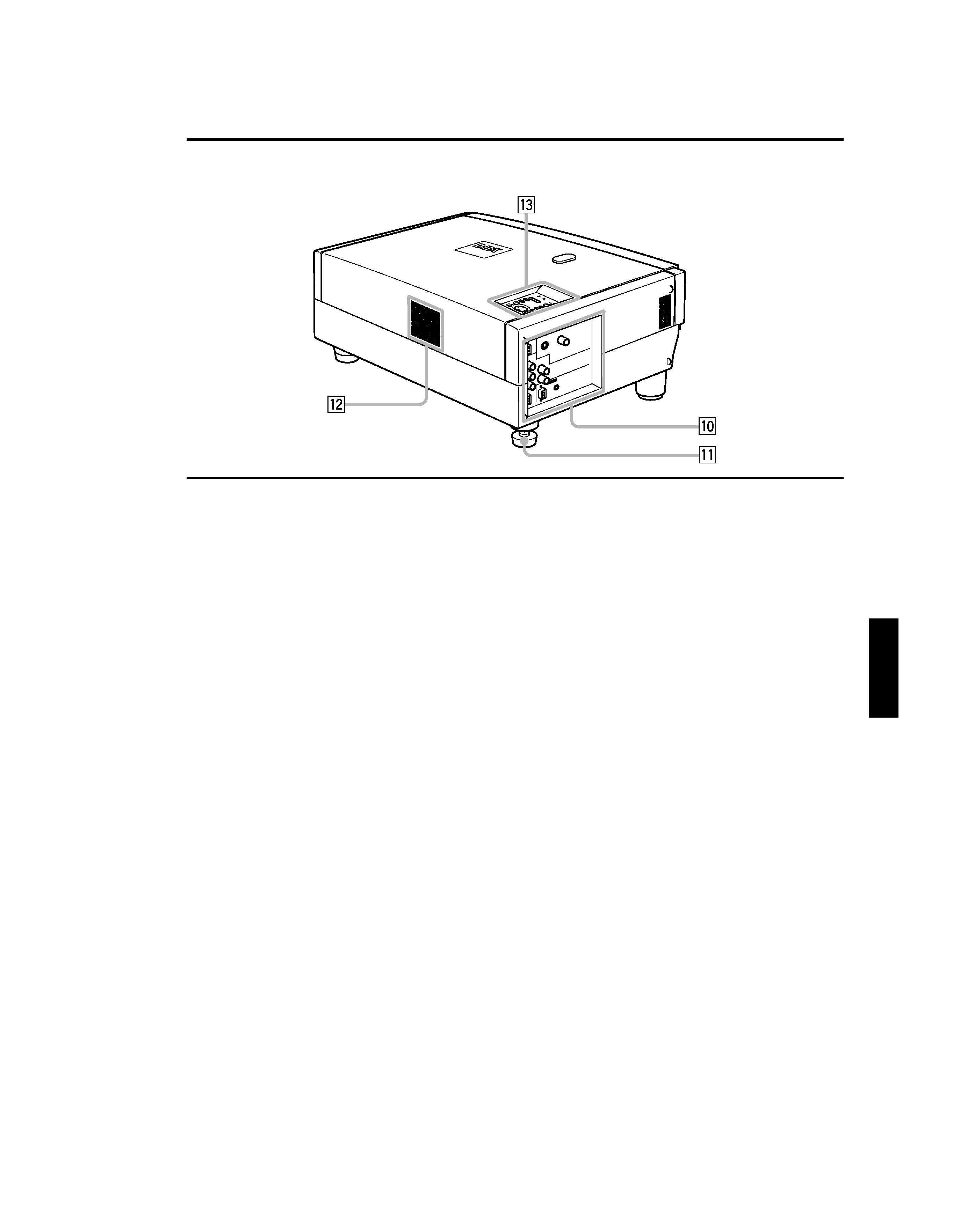
p Connector panel
For details, refer to "Connector Panel" on page 11.
q Rear adjustable foot (for leveling the projector)
It is set at the shortest position when shipped from the
factory. Turn the foot to make the projector level.
Adjustment can be made in the range of +1.5° and 1.5°
from the horizontal position. For details, refer to
"Adjusting the Inclination of the Projector" on page 16.
w Air inlet
This is the air inlet. Do not cover or obstruct this slot.
e Control panel
For details, refer to "Control Panel on the Projector" on
page 9.
VID
EO
PC
UP
LA
MP
TE
MP
ST
AN
D
BY
ME
NU
KE
YS
TO
NE
PR
ES
ET
EX
IT
EN
TE
R
OP
ER
AT
E
HID
E
