SERVICE MANUAL
SPECIFICATIONS AND PARTS ARE SUBJECT TO CHANGE FOR IMPROVEMENT
Digital Media Products Division,Tokai
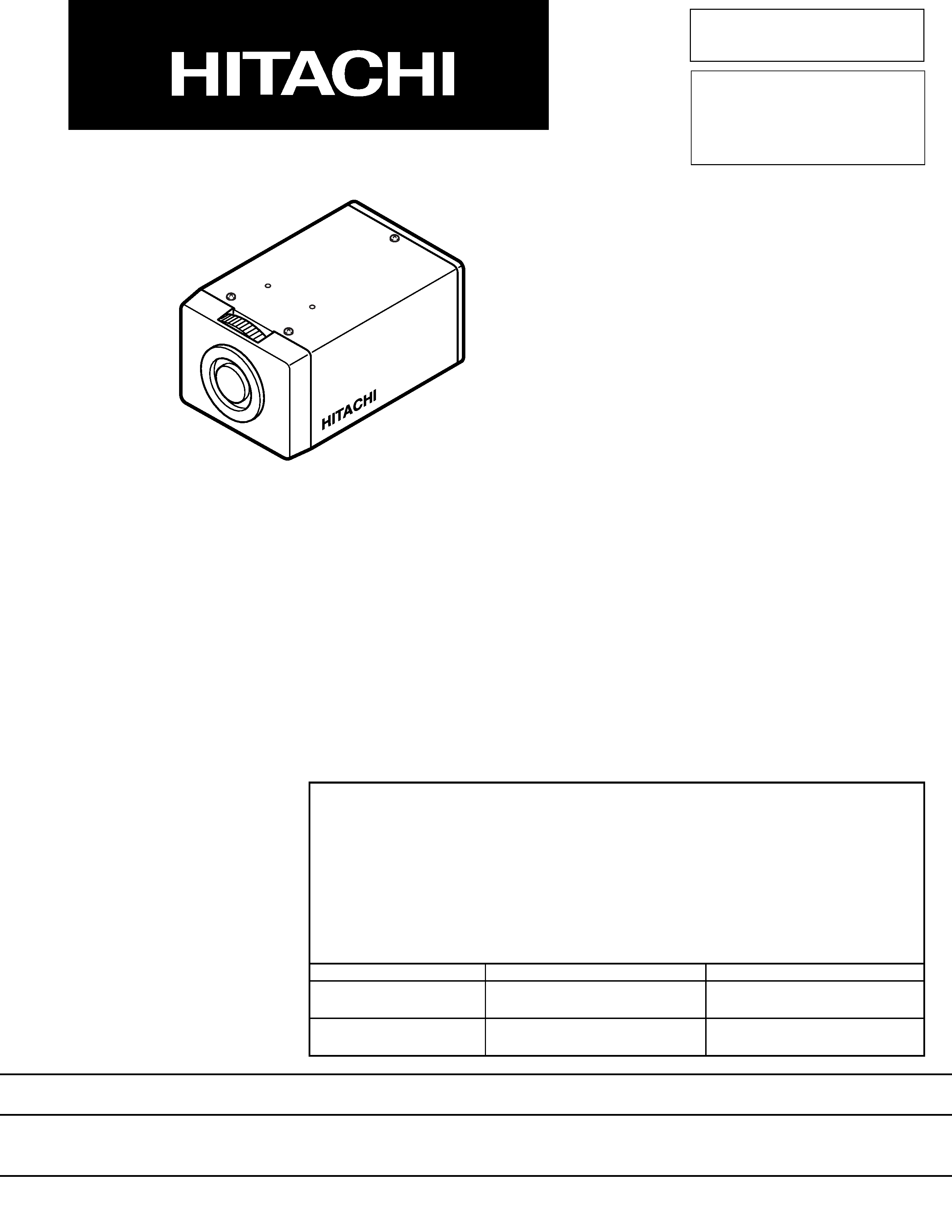
COLOUR & B/W VIDEO CAMERA
2002
March
SM8201
Servicing Method
With VK-C212E and VK-M212E, electrical parts, including semiconductors, resistors,
capacitors, etc., are not assigned as service parts:
Replace the entire circuit board assembly.
Contents included:
The contents included in this service manual are as follows, based on the above
servicing method:
Item
Contents included
Remarks
Electrical adjustment
Not included
No adjustment is necessary
when circuit boards are replaced
Schematic and circuit
Diagrams for reference
board diagrams
VKC212E
VKM212E

Many electrical and mechanical parts have special safety-related characteristics. These are often not evident from visual
inspection nor can the protection afforded by them necessarily be obtained by using replacement components rated for a
higher voltage, wattage, etc. Replacement parts which have these special safety characteristics are identified in this
Service Manual. Electrical components having such features are identified by marking with a
on the schematics and
the parts list in this Service Manual. The use of a substitute replacement component which does not have the same safety
characteristics as the HITACHI recommended replacement one, shown in the parts list in this Service Manual, may create
shock, fire, or other hazards. Product safety is continuously under review and new instructions are issued from time to time.
For the latest information, always consult the current HITACHI Service Manual. A subscription to, or additional copies for,
HITACHI Service Manual may be obtained at a nominal charge from HITACHI SALES CORPORATION.
PRODUCT SAFETY NOTICE
!
Cautions
CHAPTER 1
GENERAL INFORMATION
1. Specifications ......................................................... 1-1
2. Comparison of Specifications/
Functions with Previous Model .............................. 1-2
3. Description of Functions ........................................ 1-3
CHAPTER 2
DISASSEMBLY
Procedure .................................................................... 2-1
CHAPTER 3
EXPLODED VIEW
Overall ......................................................................... 3-1
CHAPTER 4
REPLACEMENT
PARTS LIST
Mechanical Parts List .................................................. 4-1
CHAPTER 5
BLOCK AND SCHEMATIC/
CIRCUIT BOARD DIAGRAMS
Block Diagrams
VK-C212E .................................................................... 5-1
VK-M212E ................................................................... 5-1
Schematic Diagrams (For reference)
Connection Diagram .................................................... 5-2
VK-C212E PCB1 ......................................................... 5-3
VK-C212E Process [PCB2] ......................................... 5-5
VK-C212E Power [PCB2] ............................................ 5-6
VK-M212E PCB1 ......................................................... 5-4
VK-M212E Process [PCB2] ......................................... 5-7
VK-M212E Power [PCB2] ............................................ 5-8
Circuit Board Diagrams (For reference)
VK-C212E PCB1 -Side A/B- ...................................... 5-11
VK-C212E PCB2 -Side A/B- ........................................ 5-9
VK-M212E PCB1 -Side A/B- ...................................... 5-12
VK-M212E PCB2 -Side A/B- ...................................... 5-10
Contents
CONTENTS & CAUTIONS

Notes When Using Service Manual
The following shows the contents to be noted when using service manual:
1. Value units used in parts list
The values, dielectric strength (power capacitance) and
tolerances of the resistors (excluding variable resistors)
and capacitors are indicated in the schematic diagrams
using abbreviations.
[Resistors]
Certain symbols are indicated below for value units of
resistors, capacitors and coils in parts list. When you read
them note the following regular indications:
Indication in list
Regular indication
KOHM ........................................... k
UF ................................................ µF
PF ................................................ pF
UH ................................................ µH
MH ............................................... mH
Parts
Resistor
Capacitor
Coil
2. Values in schematic diagrams
Item
Value
Tolerance
Power
capacitance
Indication
No indication ...................................
K ................................................... k
M .................................................. M
No indication ............................. ±5%
(All tolerances other than ±5% are
indicated in schematic diagrams)
No indication ............................ 1/8W
(1/16W for leadless resistors without
indication)
All capacitances other than the above
are indicated in schematic diagrams.
[Capacitors]
Item
Value
Dielectric
strength
Indication
No indication ................................. µF
P ................................................... pF
No indication .............................. 50V
(All dielectric strengths other than 50V
are indicated in schematic diagrams)
Item
Value
Indication
µ .................................................... µH
m .................................................. mH
[Coils]
3. Identifications of sides A/B in
circuit board diagrams
1) Board having a pattern on one side and parts on both
sides.
Side A: Shows discrete parts, viewed from the pattern
side.
Side B: Shows leadless parts, viewed from the
pattern side.
2) Board having patterns on both sides and parts on
both sides.
Side A: Shows parts and patterns which can be seen
when the case is opened.
Side B: Shows parts and the pattern on the back of
side A.
CAUTIONS

1 - 1
CHAPTER 1
GENERAL INFORMATION
1.
Specifications
VK-C212E: PAL
VK-M212E: CCIR
1.0 Vp-p/75 ohm
2:1 interlace
VK-C212E: 480
VK-M212E: 570
VK-C212E: 1.2 lx
VK-M212E: 0.18 lx
VK-C212E: 0.54 lx
VK-M212E: 0.08 lx
50 dB or more
0.45
VK-C212E: 1/3-inch CCD interline, complementary
color mosaic filter
VK-M212E: 1/3-inch CCD
Horizontal: 752
Vertical:
582
Horizontal: 15.625 kHz
Vertical:
50.00 Hz
Line Lock/Internal
DC:
DC iris
AES:
VK-C212E: Linear shutter (1/50 s to 1/20000 s)
VK-M212E: Linear shutter (1/50 s to 1/100000 s)
VIDEO:
Vcc = DC 12 V, 50 mA max.
Signal = 0.7 Vp-p, High impedance
AC 24 V ± 10% (50 Hz ± 1 Hz) or DC 12 V ± 10%
VK-C212E: 3.5 W or less
VK-M212E: 3 W or less
CS mount
-10 °C to +50 °C/14 °F to 122 °F,
85% RH or less (no condensation)
-20 °C to +60 °C/-4 °F to 140 °F,
95% RH or less (no condensation)
60 (W) x 54 (H) x 103.3 (D) mm
300g
Video output:
BNC
Auto-iris output:
4-pin connector
(D4-151N-100/equivalent)
Power input:
2-pin screwless terminal blocks
Iris control: DC/AES/VIDEO
BLC:
BLC/OFF
Sync mode: INT./L.L.
Line Lock Phase control
DC iris level control (adjstable POT in only DC iris mode)
Video signal system
Video output
Scanning system
Resolution (horizontal TV line)
Minimum object illumination F1.2
Minimum object illumination F0.8
S/N ratio
Gamma characteristics
Photo-image sensor
Effective pixel count
Scanning frequency (INT. sync mode)
Sync modes
Iris control
Power
Maximum power consumption
Lens mount
Operating environment
Storage environment
External dimensions
Weight
Input/output terminals
Switches
Controls

1 - 2
ITEM
Signal
Image sensor
Total number of pixels
Number of effective pixels
Sync format
Video signal output
VBS (VS)
Video (Y : Luminance)
Sync
Burst
Impedance
Connector
S/N ratio
Horizontal resolution
Minimum required illumination
White balance
Lens mount
Lens
Range in which operation is
possible
Range in which performance
is assured
Power input
Power consumption
Dimensions
(excluding protrusions)
Weight
AES function
Manual shutter speed control
White balance control
AGC ON/OFF function
ALC function
Camera ID function
Electrical zoom function
Negative/Positive selection
2.
Comparison of Specifications/Functions with Previous Model
VK-C317E
(Color video camera)
Same as in left column
1/4-inch CCD image sensor
795 (H) × 596 (V)
752 (H) × 582 (V)
Same as in left column
Same as in left column
Same as in left column
450 TV line or more
4 lx or less (F 1.2 wide angle
AGC mode NORM)
2 lx or less (F 1.2 wide angle
AGC mode HIGH)
Automatic or manual (switch-
able)
Not provided
F 1.2 Optical zoom × 2.5.
f: 2.4 mm to 6.0mm
-10 to +50 °C
10 to 85 %
+5 to 30 °C
45 to 75 %
AC 24 V ± 20% 50 Hz
DC 12 V (DC 10.8 V to
DC 40 V)
3.0 W MAX
64 (W) × 58 (H) × 152 (D) mm
370 g
Same as in left column
Provided
Automatic or manual
(switchable)
Provided
Same as in left column
Provided
Provided (× 2)
Provided
VK-C212E
(Color video camera)
PAL Format
1/3-inch CCD image sensor
795 (H) × 596 (V)
752 (H) × 582 (V)
Internal/Line Lock
1.0 Vp-p
approx. 0.7 Vp-p positive
approx. 0.3 Vp-p negative
approx. 0.3 Vp-p 8 cycles or
more
75 ohm unbalanced
BNC type
50 dB or more
460 TV line or more
2.5 lx or less (F1.2)
Automatic only
CS
Not provided
-10 to +50 °C
85% or less
-10 to +50 °C
85% or less
AC 24 V ± 10% 50 Hz
DC 12 V (DC 12 V to
DC 24 V)
5.0 W MAX
60 (W) × 46 (H) × 95 (D) mm
300 g
Provided
Not provided
Automatic only
Not provided
Provided
Not provided
Not provided
Not provided
VK-M212E
(B/W video camera)
CCIR Fromat
1/3-inch CCD image sensor
795 (H) × 596 (V)
752 (H) × 582 (V)
Internal/Line Lock
1.0 Vp-p
approx. 0.7 Vp-p positive
approx. 0.3 Vp-p negative
----------
75 ohm unbalanced
BNC type
50 dB or more
560 TV line or more
0.2 lx or less (F1.2)
Automatic only
CS
Not provided
-10 to +50 °C
85% or less
-10 to +50 °C
85% or less
AC 24 V ± 10% 50 Hz
DC 12 V (DC 12 V to
DC 24 V)
5.0 W MAX
60 (W) × 46 (H) × 95 (D) mm
300 g
Provided
Not provided
Automatic only
Not provided
Provided
Not provided
Not provided
Not provided
