CAUTION:
Before servicing this chassis, it is important that the service technician read the "Safety
Precautions" and "Product Safety Notices" in this service manual.
ATTENTION:
Avant d'effectuer l'entretien du châassis, le technicien doit lire les «Précautions de sécurité»
et les «Notices de sécurité du produit» présentés dans le présent manuel.
VORSICHT:
Vor Öffnen des Gehäuses hat der Service-Ingenieur die ,,Sicherheitshinweise" und ,,Hinweise
zur Produktsicherheit" in diesem Wartungshandbuch zu lesen.
SERVICE MANUAL
MANUEL D'ENTRETIEN
WARTUNGSHANDBUCH
Data
contained
within
this
Service
manual is subject to alteration for
improvement.
Les données fournies dans le présent
manuel d'entretien peuvent faire l'objet
de modifications en vue de perfectionner
le produit.
Die
in
diesem
Wartungshandbuch
enthaltenen Spezifikationen können sich
zwecks Verbesserungen ändern.
«MODEL NAMES»
SPECIFICATIONS AND PARTS ARE SUBJECT TO CHANGE FOR IMPROVEMENT
Plasma TV
October 2004
SM004
42PD4200
1
42PD4200 (PW1A)
PRECAUTIONS
How to clean the plasma screen panel of the monitor
Before cleaning the monitor, turn off the monitor and disconnect the power plug from the power outlet.
To prevent scratching or damaging the plasma screen face, do not knock or rub the surface with sharp or
hard objects. Clean the screen with a soft cloth moistened with warm water and dry with a soft cloth. If it is
not enough, then use a cloth with mild detergent. Do not use harsh or abrasive cleaners.
How to clean the cabinet of the monitor
Use a soft cloth to clean the cabinet and control panel of the monitor. When excessively soiled dilute a neu-
tral detergent in water, wet and wring out the soft cloth and afterward wipe with a dry soft cloth.
Never use acid/alkaline detergent, alcoholic detergent, abrasive cleaner, powder soap, OA cleaner, car wax,
glass cleaner, etc. especially because they would cause discoloration, scratches or cracks.
1. Features
Large-screen, high-definition plasma display panel
The 42-inch color plasma display panel, with a resolution of 852 (H) x 480(V) pixels, creates a high-definition,
large-screen (aspect ratio : 16:9) and low-profile flat display. Free from electromagnetic interferences from
geomagnetic sources and ambient power lines, the panel produces high-quality display images free from
color misconvergence and display distortion.
High Performance Digital Processor
A wide range of personal computer signals can be handled, from 640 x 400, 640 x 480 VGA to 1600 x 1200
UXGA.(RGB Analog input)
Easy-to-use remote control and on screen display system
The remote control included eases the work of setting display controls. Further, the on-screen display
system, displays the status of signal reception and display control settings in an easy-to-view fashion.
Power saving system
The International ENERGY STAR power saver feature saves power consumption automatically when
input signals are not available.
When connected to a VESA DPMS-compliant PC, the monitor cuts its power consumption while it is idle.
TruBass
TruBass, SRS and ( ) symbol are trademarks of SRS Labs,Inc.
TruBass technology is incorporated under license from SRS Labs, Inc.
One mini D-sub terminal and one DVI-D terminal for RGB input
The D-sub terminal can also receive the RGB-component by On-Screen Display control.
One composite/S.video input terminal and two component video input terminals added with VIDEO board
One component input is possible to switch to RGB signal input from the Menu screen.
One SCART terminal for the signal of the European standard added with VIDEO board
It operates as composite/S.video input and RGB input terminal, or composite video output terminal.
One composite video output terminal as a monitoring output added with VIDEO board
Simple type of the remote control
2
42PD4200 (PW1A)
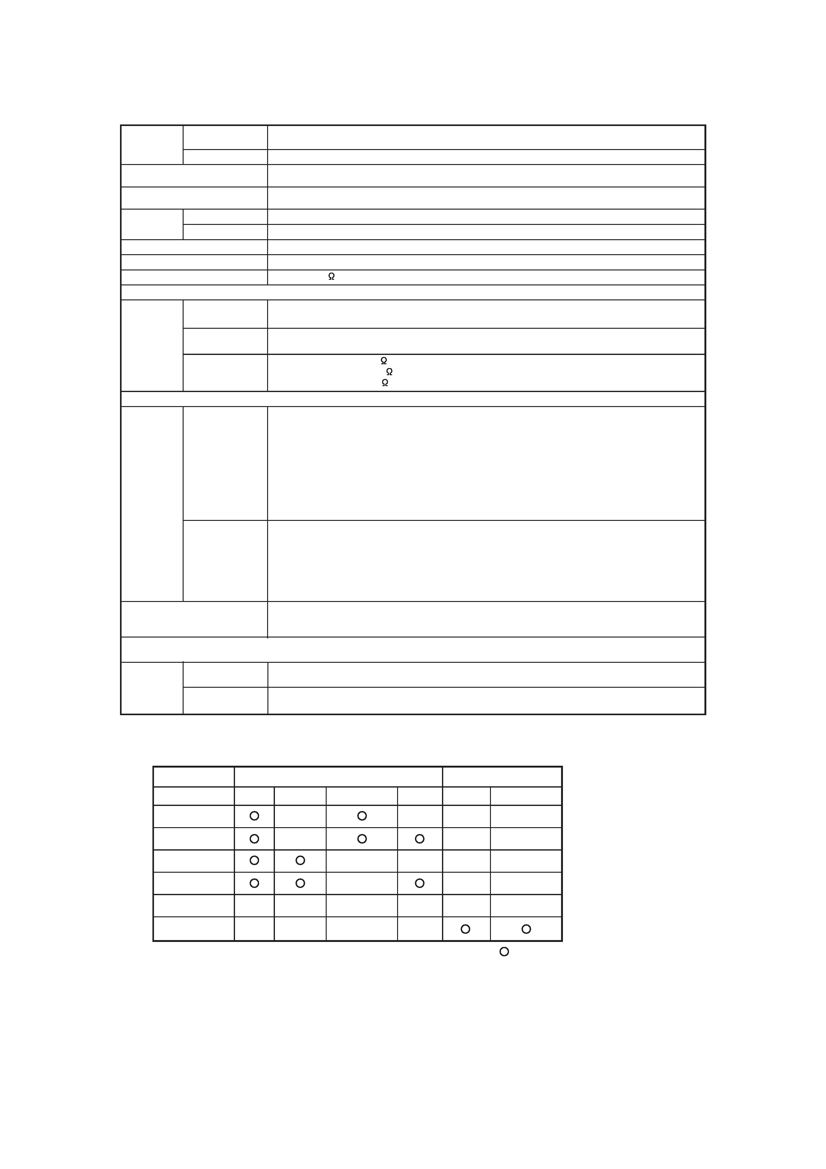
2. Specifications
Panel
Display
dimensions
Approx. 42 inches (920 (H) x 518 (V) mm, diagonal 1059mm)
Resolution
852 (H) x 480 (V) pixels
Net dimensions
(excluding Speakers/Stand)
1030 (W) x 636 (H) x 91 (D) mm
Net weight
(excluding Speakers/Stand)
33.2kg
Ambient
conditions
Temperature
Relative humidity
Operating : 20% to 80%, Storage : 20% to 90% (non-condensing)
Power supply
AC100 - 240V, 50/60Hz
Power consumption/at standby
310W / <3W
Audio output
(RGB input)
Input signals
Input terminals
RGB2 analog RGB input terminal (D-sub 15-pin)
RGB2 audio input terminal (3.5mm Stereo Mini Jack)
Video signals
0.7 V/1.0 Vp-p, analog RGB (Recommended Signal)
480i, 576i, 480p, 576p, 1080i/50, 1080i/60, 720p/60
Sync signals
H/V separate, TTL level [2K ]
H/V composite, TTL level [2K ]
Sync on green, 0.3 Vp-p [75 ]
(Video input)
Input signals
Input terminals
AV1: composite video input terminal (RCA)
AV1: Y PB PR video input terminal (RCA)
AV1: L/R audio input terminal (RCA)
AV2: composite video input terminal (RCA)
AV2: Y/G PB/B PR/R video input terminal (RCA)
AV2: L/R audio input terminal (RCA)
AV3: composite video input terminal (RCA)
AV3: S video input terminal (RCA)
AV3: L/R audio input terminal (RCA)
AV4: composite video / S video / RGB / L/R audio input terminal (Scart)
Video signals
RF Video System
AV1: PAL,SECAM,NTSC4.43,NTSC3.58
AV1: 480i, 576i, 480p, 576p, 1080i/50, 1080i/60, 720p/60
AV2: PAL,SECAM,NTSC4.43,NTSC3.58
AV2: 480i, 576i, 480p, 576p, 1080i/50, 1080i/60, 720p/60, RGB
AV3: PAL,SECAM,NTSC4.43,NTSC3.58
AV4: PAL,SECAM,NTSC4.43,NTSC3.58
AV4: RGB
Video output Signal
OUTPUT (MONITOR): composite video monitor-output terminal (RCA)
OUTPUT (MONITOR): L/R audio monitor- output terminal (RCA)
AV4: composite video / L/R audio monitor-output terminal (SCART)
Operating : 5
to 35
, Storage : -15
to 60
12W + 12W (6
)
Input signals
(RF input)
Input terminals
ANT : 75 Unbalanced
PAL B, G, H / I / D, K
SECAM B, G / D, K / K1
Applicable video signals for each input terminal
Terminal
RCA/SCART
D-sub
Signal
CVBS
S-video
Component
RGB
RGB
Component
AV1
AV2
AV3
AV4
RGB1
RGB2
(
:Available)
3
42PD4200 (PW1A)
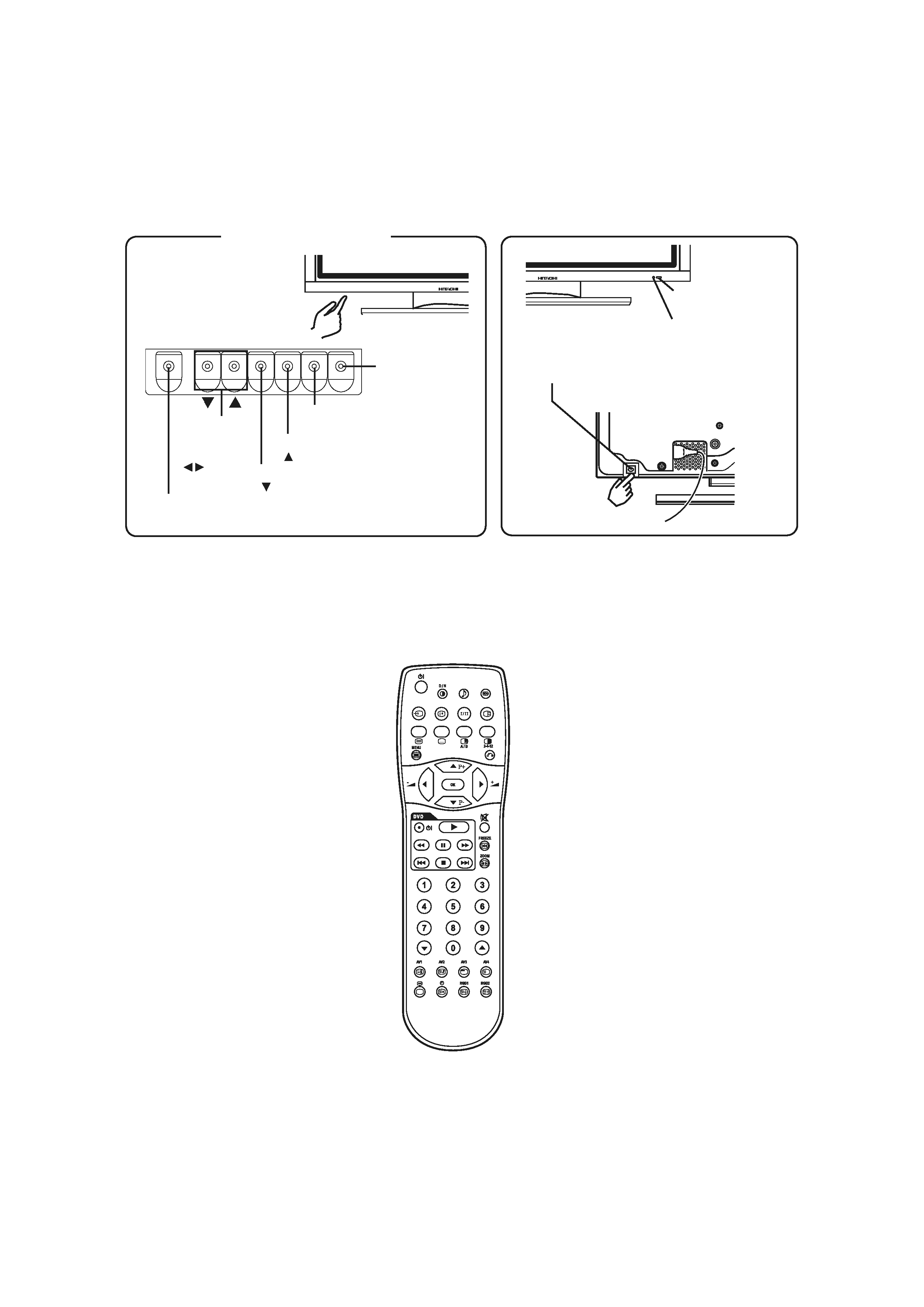
3. Component names
Remote-control
receiver
PROGRAM DOWM button
(
SELECT button)
INPUT SELECT button
(OK button)
PROGRAM UP button
(
SELECT button)
· Adjustment buttons are located
on the bottom.
· The back cover is provided with
indications to distinguish the
adjustment buttons.
SUB-POWER button
Control panel
VOLUME
UP/DOWN
buttons
(ADJUST
buttons)
Main power switch
· The main power switch is located at the back, on the
lower surface.
Indicating lamp
MENU button
· ( ) indicates the function while the MENU is displayed on the screen.
[Remote control]
[Main unit]
CLE-958
4
42PD4200 (PW1A)
4. Service points
Lead free solder
This product uses lead free solder (unleaded) to help preserve the environment. Please read these
instructions before attempting any soldering work.
Caution: Always wear safety glasses to prevent fumes or molten solder from getting into the eyes. Lead
free solder can splatter at high temperatures (600°C).
Lead free solder indicator
Printed circuit boards using lead free solder are engraved with an "F."
Properties of lead free solder
The melting point of lead free solder is 40-50°C higher than leaded solder.
Servicing solder
Solder with an alloy composition of Sn-3.0Ag-0.5Cu or Sn-0.7Cu is recommended.
Although servicing with leaded solder is possible, there are a few precautions that have to be taken. (Not
taking these precautions may cause the solder to not harden properly, and lead to consequent malfunctions.)
Precautions when using leaded solder
Remove all lead free solder from soldered joints when replacing components.
If leaded solder should be added to existing lead free joints, mix in the leaded solder thoroughly after the
lead free solder has been completely melted (do not apply the soldering iron without solder).
Servicing soldering iron
A soldering iron with a temperature setting capability (temperature control function) is recommended.
The melting point of lead free solder is higher than leaded solder. Use a soldering iron that maintains a high
stable temperature (large heat capacity), and that allows temperature adjustment according to the part being
serviced, to avoid poor servicing performance.
Recommended soldering iron:
Soldering iron with temperature control function (temperature range: 320-450°C)
Recommended temperature range per part:
Part
Soldering iron temperature
Mounting (chips) on mounted PCB
320°C±30°C
Mounting (chips) on empty PCB
380°C±30°C
Chassis, metallic shield, etc.
420°C±30°C
(1) FILTER PWB, SW PWB, LED/RECEIVER PWB, TACT SW PWB, SP TERMINAL(L/R) PWB
(2) AUDIO PWB, JOINT PWB
(3) VIDEO PWB
(4) FORMATTER PWB
(5) POWER BOARD
The PWB assembly which has used lead free solder
