PLASMA TELEVISION
AVC (Audio Video Control Center) & Plasma Display Monitor
32HDT50
42HDT50
50HDT50
OPERATING GUIDE
IMPORTANT SAFETY INSTRUCTIONS
2-3
FIRST TIME USE
4-23
THE REMOTE CONTROL
ON-SCREEN DISPLAY
USEFUL INFORMATION INDEX
75-83
Setup
Locks
Ch. Manager
Audio
Video
Move
SEL
Sel
POWER
TV
VCR
CBL
DVD
1
2
4
56
3
7
89
0
INFO
SLEEP
A/V
NET
EXIT
MENU
CH
VOL
MUTE
PIP
PIP
CH
SWAP
FREEZE
PIP
MODE
PIP
ACCESS
VIDEO
SOURCE
WIZARD
REC
SELECT
TV/RGB
ASPECT
STB
ANT
LA
ST
CH
VCR
PLUS
+
SVCS
GU
ID
E/
TV
S
C
H
D
VID 1
VID
2
VI
D
3
VI
D
4
V
ID
5
TAPE
CD
AMP
MODE
CLU-5723TSI
41-64
24-40
Locks
Chan. Manager
Aspect
Audio
Video
Move
SEL
Sel
Setup
USING THE RGB INPUT
OF THE PLASMA TV
65-74
2
IMPORTANT
SAFETY POINTS YOU SHOULD KNOW ABOUT
YOUR HITACHI PLASMA TELEVISION
Our reputation has been built on the quality, performance, and ease of service of HITACHI Plasma Televisions.
Safety is also foremost in our minds in the design of these units. To help you operate these products properly, this
section illustrates safety tips which will be of benefit to you. Please read it carefully and apply the knowledge you
obtain from it to the proper operation of your HITACHI Plasma Television.
Please fill out your warranty card and mail it to HITACHI. This will enable HITACHI to notify you promptly in the
improbable event that a safety problem should be discovered in your product model.
Follow all warnings and instructions marked on this plasma television. Plasma television consists of AVC center and display monitor.
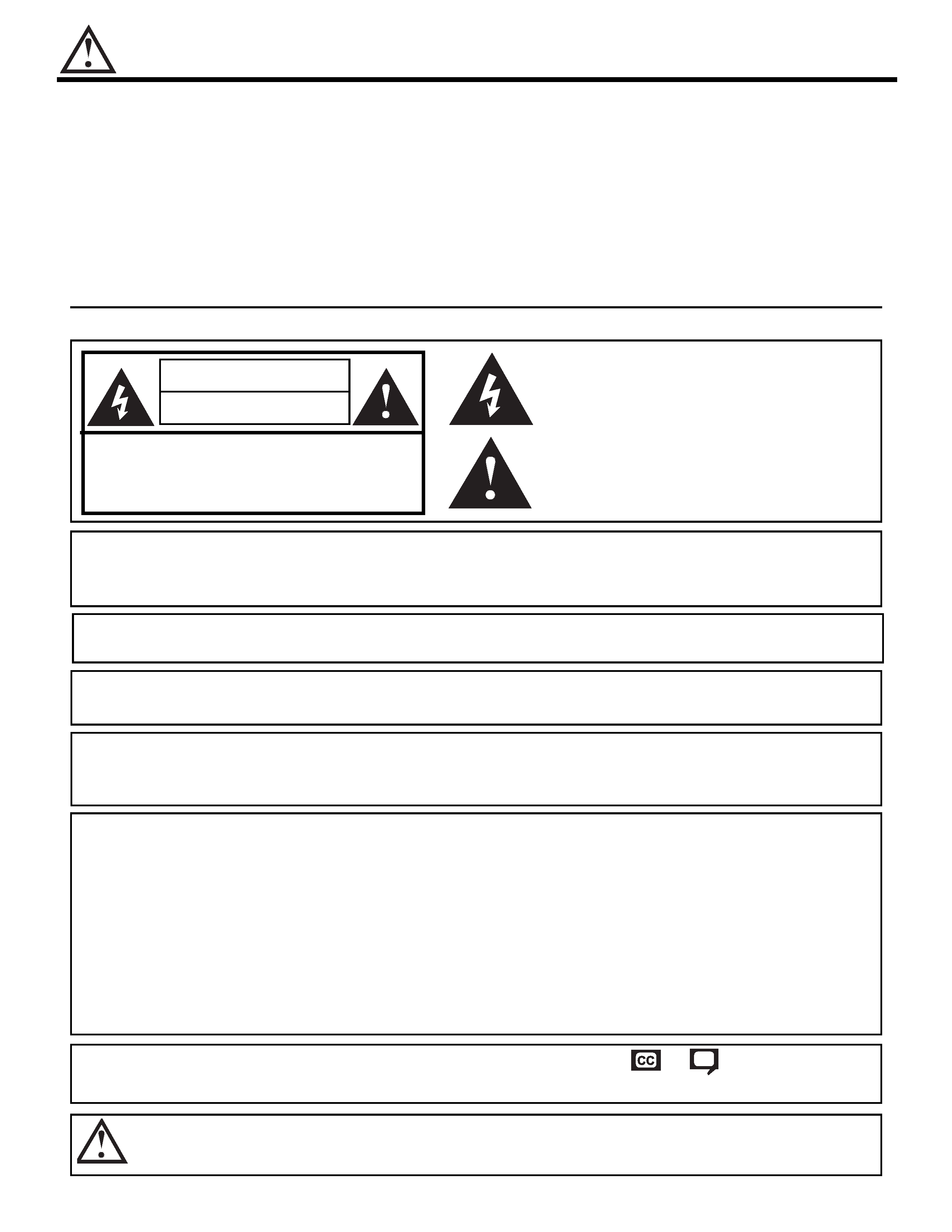
CAUTION
RISK OF ELECTRIC SHOCK
DO NOT OPEN
CAUTION: TO REDUCE THE RISK OF ELECTRIC SHOCK,
DO NOT REMOVE COVER (OR BACK).
NO USER SERVICEABLE PARTS INSIDE.
REFER SERVICING TO QUALIFIED SERVICE PERSONNEL.
The lightning flash with arrowhead symbol, within an equilateral
triangle, is intended to alert the user to the presence of uninsulated
"dangerous voltage" within the product's enclosure that may be of a
sufficient magnitude to constitute a risk of electric shock to persons.
The exclamation point within an equilateral triangle, is intended to
alert the user to the presence of important operating and
maintenance (servicing) instructions in the literature accompanying
the appliance.
WARNING:
TO PREVENT FIRE OR SHOCK HAZARD, DO NOT EXPOSE THIS PLASMA TELEVISION
TO RAIN OR MOISTURE.
NOTE:
· There are no user serviceable parts inside the AVC center/display monitor.
· Model and serial numbers are indicated on back side of the AVC center/display monitor.
POWER SOURCE
THIS PLASMA TELEVISION IS DESIGNED TO OPERATE ON 120 VOLTS 60Hz, AC CURRENT. INSERT
THE AVC CENTER AND DISPLAY MONITOR POWER CORD INTO A 120 VOLT 60Hz OUTLET.
TO PREVENT ELECTRIC SHOCK, DO NOT USE THE PLASMA TELEVISION'S (POLARIZED) PLUG WITH
AN EXTENSION CORD, RECEPTACLE, OR OTHER OUTLET UNLESS THE BLADES AND GROUND
TERMINAL CAN BE FULLY INSERTED TO PREVENT BLADE EXPOSURE.
NEVER CONNECT THE AVC CENTER/DISPLAY MONITOR TO 50Hz, DIRECT CURRENT, OR ANYTHING
OTHER THAN THE SPECIFIED VOLTAGE.
CAUTION: Never remove the back cover of the AVC center/display monitor as this can expose you to very high
voltages and other hazards. If the television does not operate properly, unplug the Plasma Television and
call your authorized dealer or service center.
NOTE:
This Plasma Television will display television closed captioning, (
or
), in accordance with
paragraph 15.119 of the FCC rules.
CAUTION: Adjust only those controls that are covered in the instructions, as improper changes or modifications not
expressly approved by HITACHI could void the user's authority to operate the Plasma Television.
MODIFICATIONS:
The FCC requires the user to be notified that any changes or modifications made to this device that
are not expressly approved by Hitachi America, Ltd. Home Electronics Division may void the user's
authority to operate the equipment.
SAFETY TIPS
3
Read before operating equipment
Follow all warnings and instructions marked on this television.
1. Read these instructions.
2. Keep these instructions.
3. Heed all warnings.
4. Follow all instructions.
5. Do not use this apparatus near water.
6. Clean only with a dry cloth.
7. Do not block any ventilation openings.
Install in
accordance with the manufacturer's instructions.
8. Do not install near any heat sources such as radiators,
heat registers, stoves, or other apparatus (including
amplifiers) that produce heat.
9. Do not defeat the safety purpose of the polarized or
grounding-type plug. A polarized plug has two blades
with one wider than the other. A grounding type plug
has two blades and a third grounding prong. The wide
blade or the third prong are provided for your safety. If
the provided plug does not fit into your outlet, consult
an electrician for replacement of the obsolete outlet.
10. Protect the power cord from being walked on or
pinched particularly at plugs, convenience receptacles,
and the point where they exit from the apparatus.
11. Only use the attachments/accessories specified by the
manufacturer.
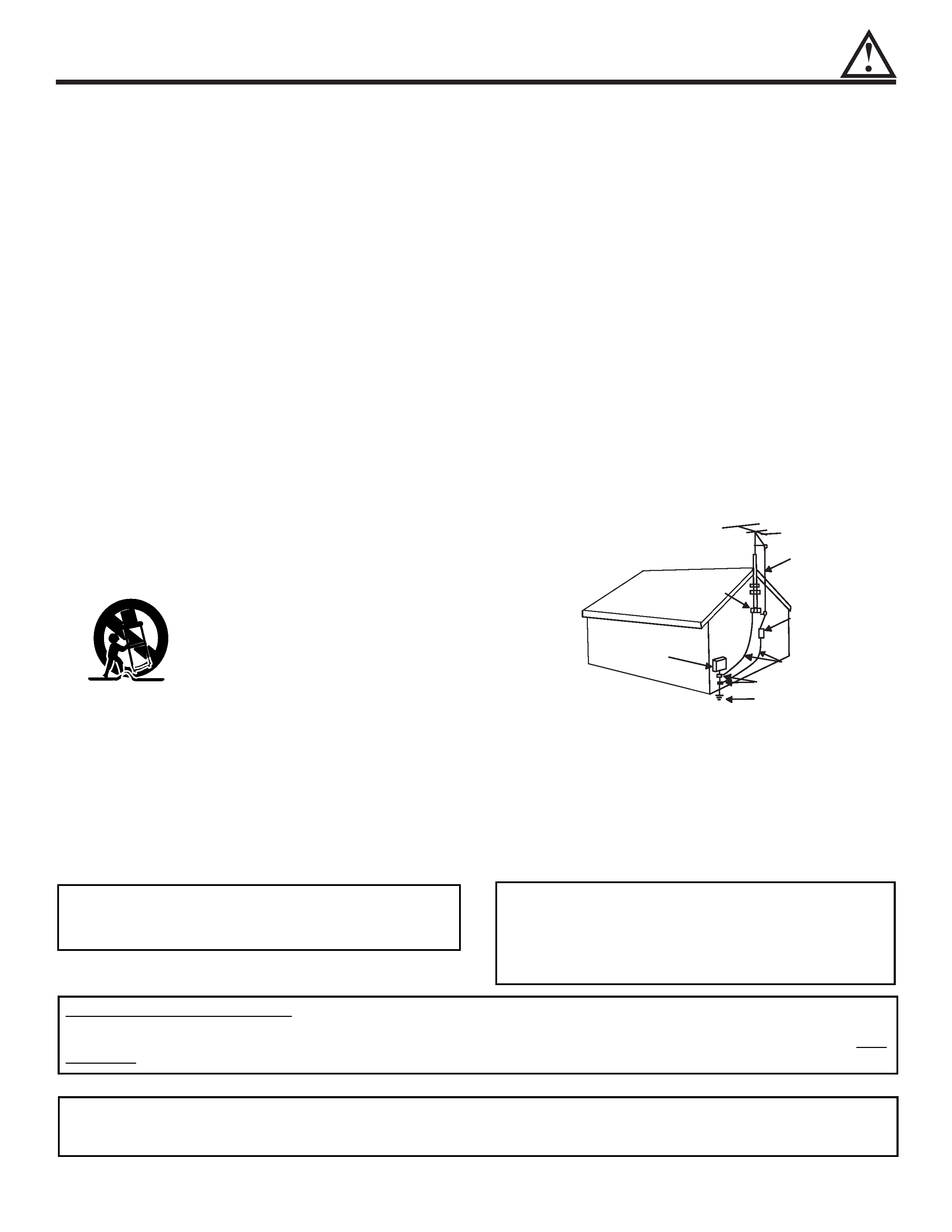
12.
Use only with the cart, stand, tripod, bracket,
or table specified by the manufacturer, or
sold with the apparatus. When a cart is
used, use caution when moving the
cart/apparatus combination to avoid injury
from tip-over.
13. Unplug this apparatus during lightning storms or when
unused for long periods of time.
14. Refer all servicing to qualified service personnel.
Servicing is required when the apparatus has been
damaged in any way, such as power-supply cord or
plug is damaged, liquid has been spilled or objects
have fallen into apparatus, the apparatus has been
exposed to rain or moisture, does not operate
normally, or has been dropped.
15. Televisions
are
designed
to
comply
with
the
recommended safety standards for tilt and stability.
Do not apply excessive pulling force to the front, or top,
of the cabinet which could cause the product to
overturn resulting in product damage and/or personal
injury.
16. Follow instructions for wall, shelf or ceiling mounting as
recommended by the manufacturer.
17. An outdoor antenna should not be located in the
vicinity of overhead power lines or other electrical
circuits.
18. If an outside antenna is connected to the receiver be
sure the antenna system is grounded so as to provide
some protection against voltage surges and built up
static charges.
Section 810 of the National Electric
Code, ANSI/NFPA No. 70-1984, provides information
with respect to proper grounding for the mast and
supporting structure, grounding of the lead-in wire to
an antenna discharge unit, size of grounding
connectors, location of antenna-discharge unit,
connection to grounding electrodes and requirements
for the grounding electrode.
Note to the CATV system installer: This reminder is
provided to call the CATV system installer's attention to
Article 820-40 of the NEC that provides guidelines for
proper grounding and, in particular, specifies that the
cable ground shall be connected to the grounding
system of the building, as close to the point of cable
entry as practical.
ANTENNA
LEAD IN
WIRE
ANTENNA
DISCHARGE UNIT
(NEC SECTION 810-20)
GROUNDING CONDUCTORS
(NEC SECTION 810-21)
GROUNDING CONDUCTORS
POWER SERVICE GROUNDING
ELECTRODE SYSTEM
(NEC ART 250 PART H)
NEC NATIONAL ELECTRICAL CODE
ELECTRIC
SERVICE
EQUIPMENT
GROUND
CLAMP
Do not place any objects on the top of the
television which may fall or cause a child to climb
to retrieve the objects.
Disposal of this product may require specific
instructions pertaining to your resident state. For
disposal or recycling information, please contact
your local authorities or the Electronic Industries
Alliance: www.eiae.org.
PREVENTION OF SCREEN BURN
Continuous on-screen displays such as video games, stock market quotations, computer generated graphics, and other fixed (non-
moving) patterns can cause permanent damage to television receivers. Such "SCREEN BURNS" constitute misuse and are NOT
COVERED by your HITACHI Factory Warranty.
PUBLIC VIEWING OF COPYRIGHTED MATERIAL
Public viewing of programs broadcast by TV stations and cable companies, as well as programs from other sources, may require
prior authorization from the broadcaster or owner of the video program material.
ACCESSORIES
4
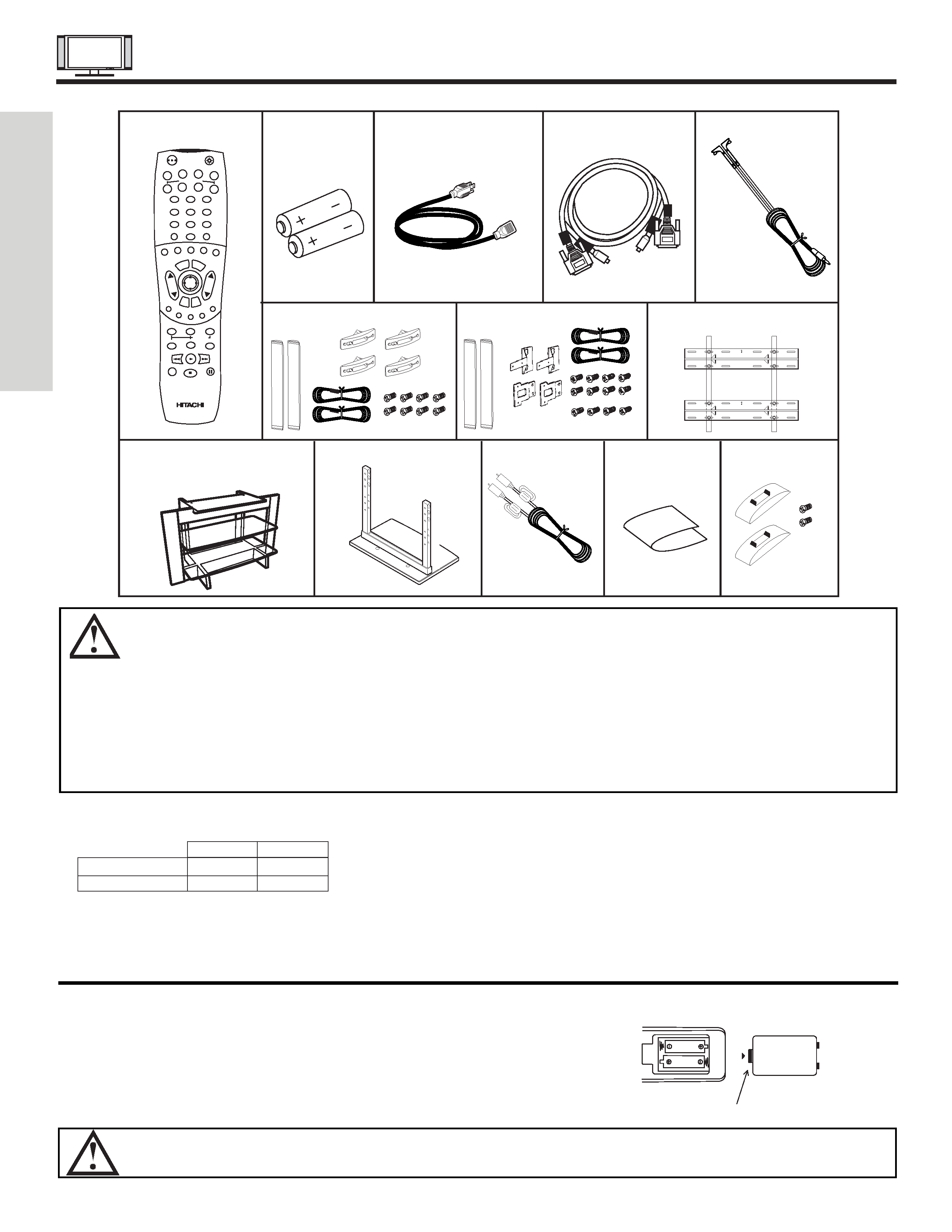
1. Remote Control Unit CLU-5726TSI (P# HL01826).
7. Speaker Accessories (50" only) (P#GM01232).
2. Two "AA" size, 1.5V batteries (P# FQ00021).
8. Wall Mount Unit WM50 (Optional) (P#QX00563).
3. Power Cord:
9. 32" Stand (SPD32 P# H520441) (Optional).
42" Stand (SPD42 P# H520442) (Optional).
10. 50" Table Top Stand (50STD3) (P#QD35632).
4. Monitor Connection Cable (P#EW07883).
11. Sub Woofer Cable (P# VZ11701).
5. Two IR Mouse cables (P# EY01641).
12. Cleaning Cloth (P#MS00803).
6. Speaker Accessories (42" only) (P#GM01193).
13. AVC Stand Accessories (P#QJ01081).
REMOTE CONTROL BATTERY INSTALLATION AND REPLACEMENT
1. Open the battery cover of the remote control by pushing the notched part of the cover with your fingers and pulling the
cover off.
2. Insert two new "AA" size batteries for the remote control. When replacing
old batteries, push them towards the springs and lift them out.
3. Match the batteries to the (+) and (-) marks in the battery compartment.
4. Replace the cover.
BOTTOM VIEW
Lift up on tab to
remove back cover.
CAUTION: Danger of explosion if battery is incorrectly replaced. Replace with the same or equivalent type.
CAUTION: 1.
The plasma display wall mount unit WM50 is for use only with Hitachi model 32HDT50, 42HDT50 and
50HDT50.
2.
Ceiling mounting is not recommended.
Mounting the panel on the ceiling does not provide adequate
ventilation for the electronics or proper support for the front glass panel. This plasma television product is
designed for a maximum tilting angle of 45 degrees from vertical.
3.
This SPD32 PDP stand for use only with Hitachi 32HDT50. Use with other apparatus is capable of resulting
in instability causing possible injury.
4.
This SPD42 PDP stand for use only with Hitachi 42HDT50. Use with other apparatus is capable of resulting
in instability causing possible injury.
5.
This 50STD3 stand for use only with Hitachi 50HDT50. Use with other apparatus is capable of resulting in
instability causing possible injury. See important marking located on bottom of stand.
POWER
TV
VCR
CBL
DVD
1
2
4
56
3
7
89
0
INFO
SLEEP
A/V NET
EXIT
MENU
CH
VOL
MUTE
PIP
SURF
SWAP
FREEZE
PIP MODE
PIP ACCESS
DAY/NIGHT
SOURCE WIZARD
REC
SELECT
TV/RGB
ASPECT
STB
ANT
LAST
CH
VID
1
VID 2
VID 3
VID 4
VID
5
PVR
CD
AMP
VIDEO
REMOTE
BATTERIES
POWER CORD
MONITOR
IR MOUSE
CONTROL
CONNECTION CABLE
CABLE
3.
4.
5.
SPEAKER ACCESSORIES
(42")
1.
WALL MOUNT UNIT WM50
(OPTIONAL)
PDP TV STAND (OPTIONAL)
32" (SPD32 P#H520441)
42" (SPD42 P#H520442)
8.
9.
50STD3 Table Top Stand
10.
2.
SPEAKER ACCESSORIES
(50")
6.
7.
Subwoofer Cable
11.
AVC Stand
Accessories
12.
13.
Cleaning Cloth
Check to make sure you have the following accessories before disposing of the packing material.
FIRST
TIME
USE
32"/42"
50"
Plasma Monitor
EV01841
EV01861
AVC
EV01841
EV01841
HOW TO SETUP YOUR NEW HITACHI PLASMA TELEVISION
5
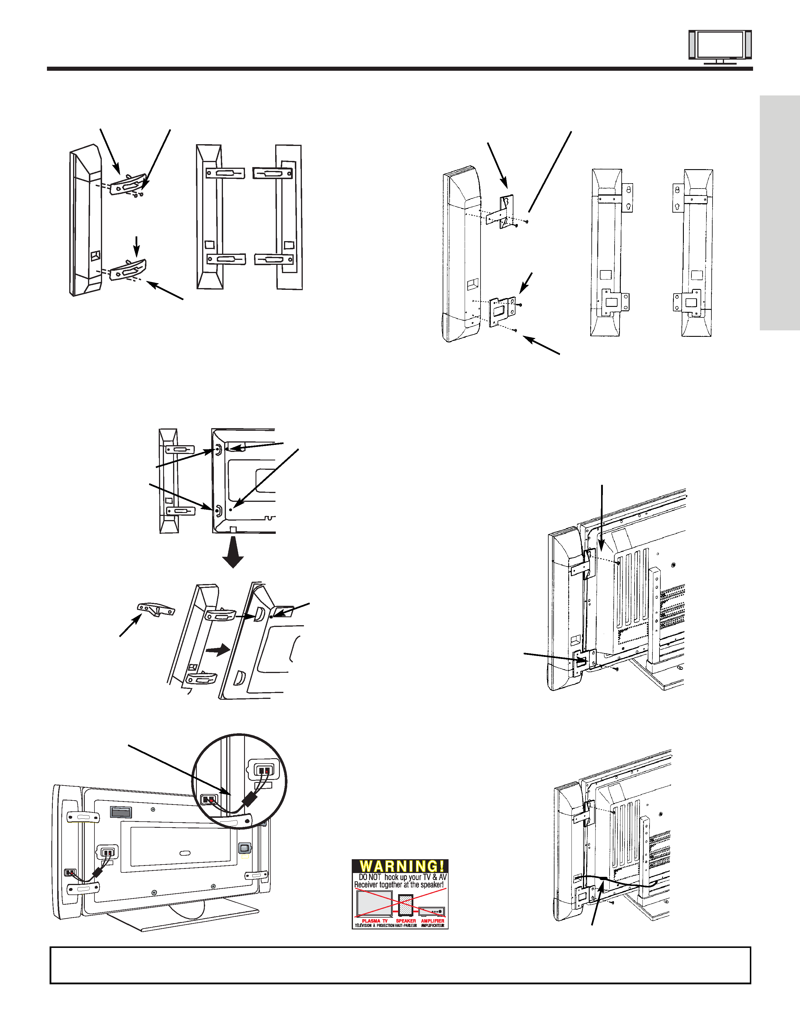
SPEAKER INSTALLATION 42"
1.
Screw the speaker holder to the speakers as shown below.
2.
Loosen 4 screws (A) (two on the left and two on the right).
3.
Completely unscrew 4 screws (B) (two on the left and two on
the right).
4.
Hook the speaker holders to the loosened screws (A).
5.
Screw the speaker holders to the Display Monitor with
screws (B).
6.
Tighten screws (A).
Speaker Holder
Speaker
Holder
Screw x2
Screw x2
(R)
(R)
(L)
(R) Speaker
Loosen
Screw
(A)
Unscrew (B)
Completely
Bottom View
of Speaker
Holder
Hook this
portion to the
loose screws
(A).
Screw in
screws (B)
Insert
horizontally from
the side
7.
Connect the speaker wires as shown below. (Make sure the
core is toward the display monitor side.)
NOTES:
Do not connect speakers simultaneously to the speaker terminal of the Plasma TV and an external amplifier.
Core
FIRST
TIME
USE
Speaker Holder
Speaker Holder
Screw x2
Screw x2
(R)
(R)
(L)
Screw in
screws (C)
Screw in
screws (D)
SPEAKER INSTALLATION 50"
1.
Screw the speaker holder to the speakers as shown below.
2.
Screw in screw (C).
3.
Hook the upper speaker holder to the screw in (C).
4.
Screw in the lower speaker holder (D).
5.
Tighten screws (C) and (D).
6.
Connect the speaker wires as shown below. (Make sure the
core is toward the display monitor side.)
Ferrite Core
