JUN. 1994
R
(with price)
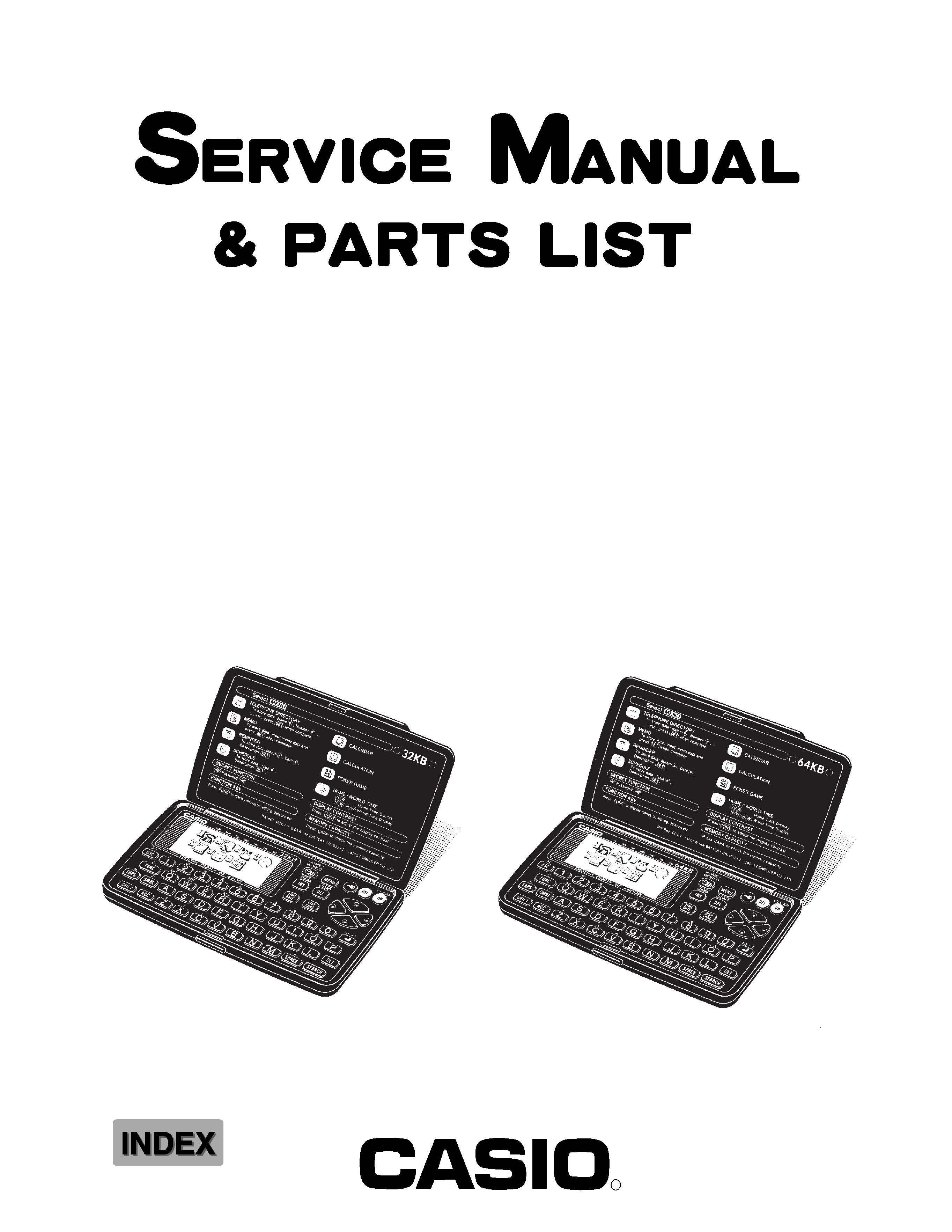
SF-4400(LX-594A)
SF-4600B(LX-594E/F)
SF-4400
SF-4600B

CONTENTS
1.
SCHEMATIC DIAGRAM .................................................................................................... 1
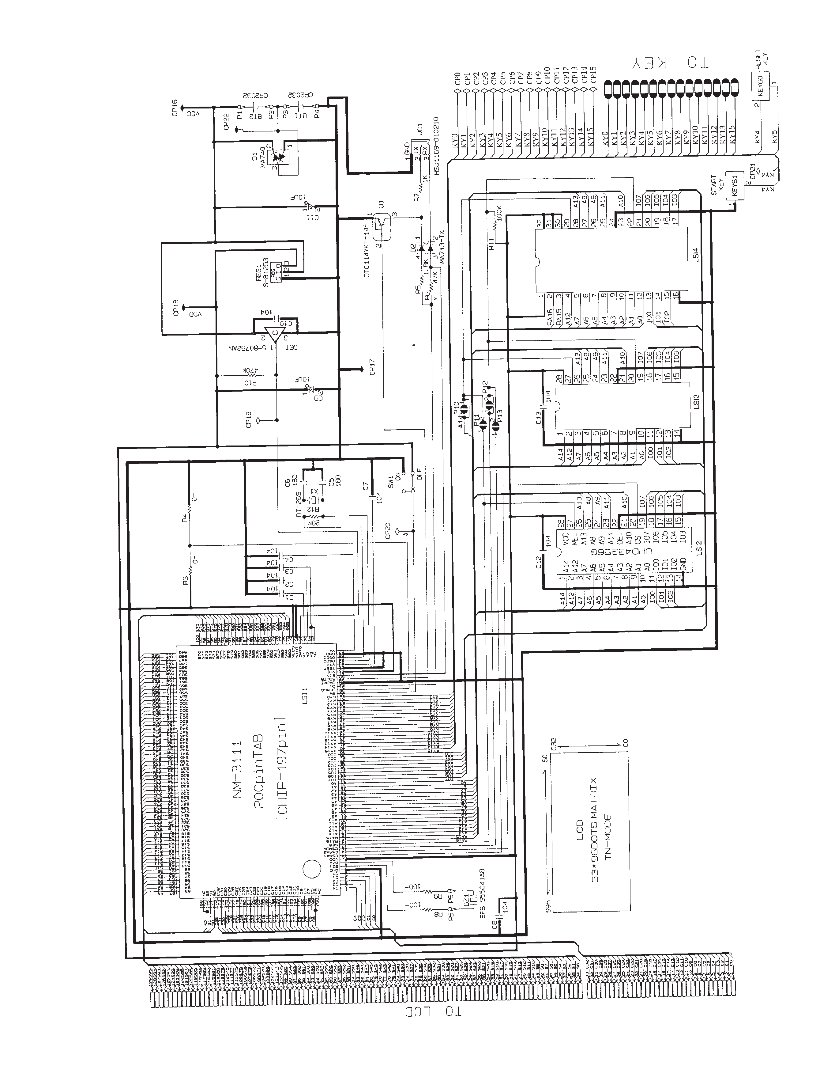
1-1. MAIN PCB .................................................................................................................. 1
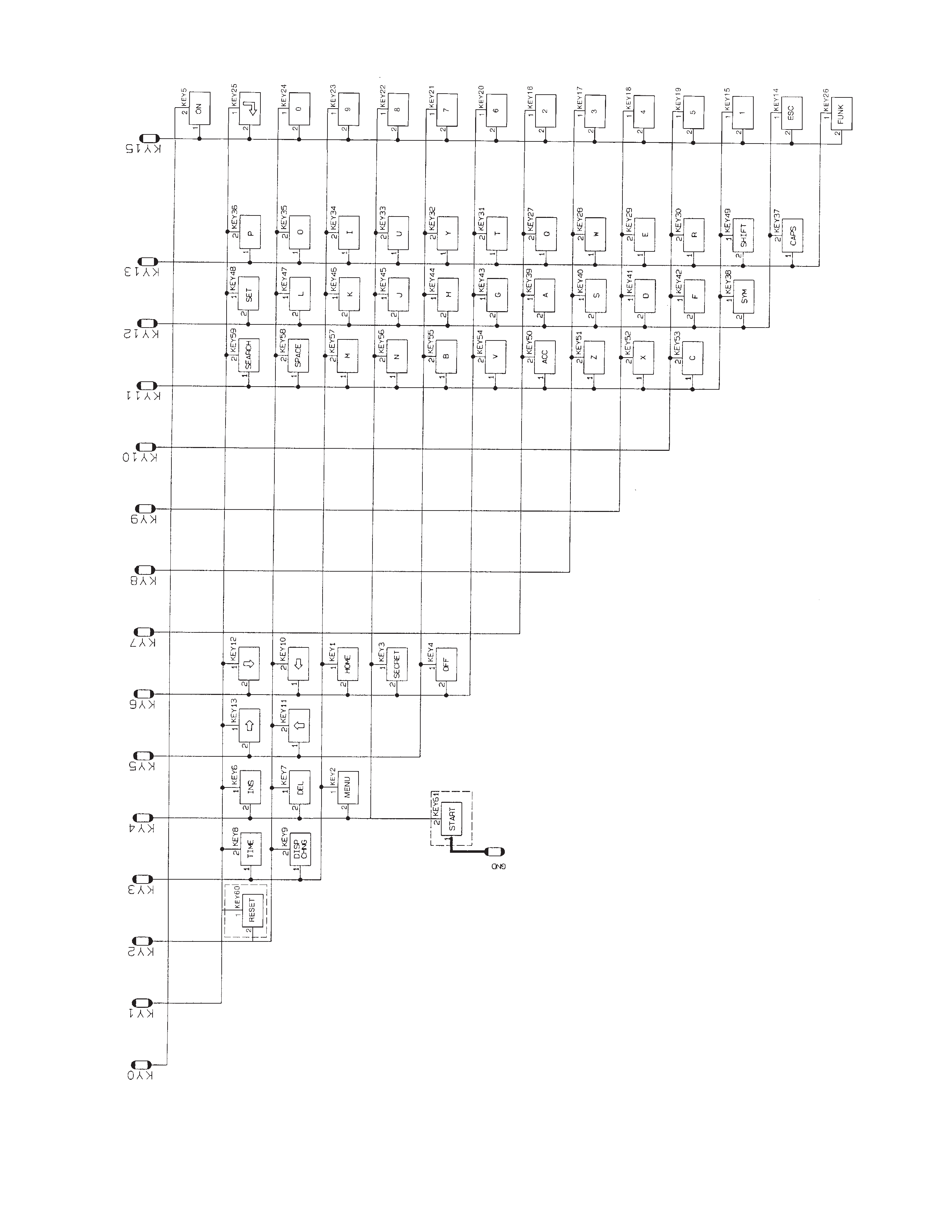
1-2. KEY MATRIX ............................................................................................................. 2
2.
SPECIFICATIONS ............................................................................................................. 3
3.
TO REPLACE THE BATTERIES ....................................................................................... 5
4.
DATA TRANSFER ............................................................................................................. 6
5.
OPERATION REFERENCE ............................................................................................. 10
5-1. RESET OPERATION ............................................................................................... 10
5-2. TO ADJUST THE DISPLAY CONTRAST ............................................................... 11
5-3. TO CHECK THE MEMORY STATUS ...................................................................... 11
5-4. THE SOUND MENU ................................................................................................. 11
6.
LSI, IC (Pin function) ...................................................................................................... 12
6-1. CPU .......................................................................................................................... 12
6-2. RAM:
µPD43256G-101215LL (LSI2,LSI3) ............................................................... 13
6-3. VOLTAGE REGULATOR:S-81253SGUP (REG1) .................................................. 14
6-4. VOLTAGE DETECTOR:S-80752AN (DET1) ........................................................... 14
7.
TROUBLESHOOTING ..................................................................................................... 15
8.
HARD CHECK ................................................................................................................. 18
9.
ASSEMBLY VIEW ........................................................................................................... 23
10. PARTS LIST .................................................................................................................... 25

-- 1 --
1.
SCHEMATIC DIAGRAM
1-1. MAIN PCB
NOTE: 1. LSI4, R3, R11 are not mounted.
2. R1, R2 are not used.

-- 2 --
1-2. KEY MATRIX

-- 3 --
2.
SPECIFICATIONS
Data storage:
Storage and recall of telephone, memo, schedule, reminder data; calendar display; secret area; editing;
memory status display.
Clock:
World time; reminder alarm; schedule alarm; daily alarm; accuracy under normal temperatures:
±3
seconds average.
Calculation:
10-digit arithmetic calculations; arithmetic constants (+, , x,
÷); independent memory; percentages;
square roots; 20-digit approximations; date calculations; other mixed calculations.
General:
Display element:
16-column x 4-line LCD
Memory capacity:
SF-4400:
32 KB (28579 bytes)
SF-4600B: 64 KB (61347 bytes)
Main component:
LSI
Power supply:
2 lithium batteries (CR2032)
Power consumption:
0.05W
Battery life:
Approximately 450 hours continuous operation in Telephone Directory
Approximately 380 hours repeating one minute of input and 10 minutes of display in Telephone
Directory
Approximately 12 months for memory backup
Auto power off:
Approximately 6 minutes after last key operation
Operating temperature: 0
°C ~ 40°C (32°F ~ 104°F)
Dimensions:
Unfolded:
10.6H x 141W x 159.5Dmm (3/8"H x 5 1/2"W x 6 1/4"D)
Folded:
12.4H x 141W x 82Dmm (1/2"H x 5 1/2"W x 3 1/4"D)
Weight:
98.2g (3.5 oz)
Current consumption:
Storage Capacity:
The 64K bytes memory capacity (32K bytes for SF-4400) includes a 61347 bytes user area (28579
bytes for SF-4400). The following shows examples of what this means for the storage of data in
each mode.
Telephone Directory:
Approximately 2920 (1360 for SF-4400), under the following conditions:
8-character name
10-character telephone number
Power switch
TYP. [
µA]
MAX [
µA]
OFF
5.15
10.0
ON
256
420
