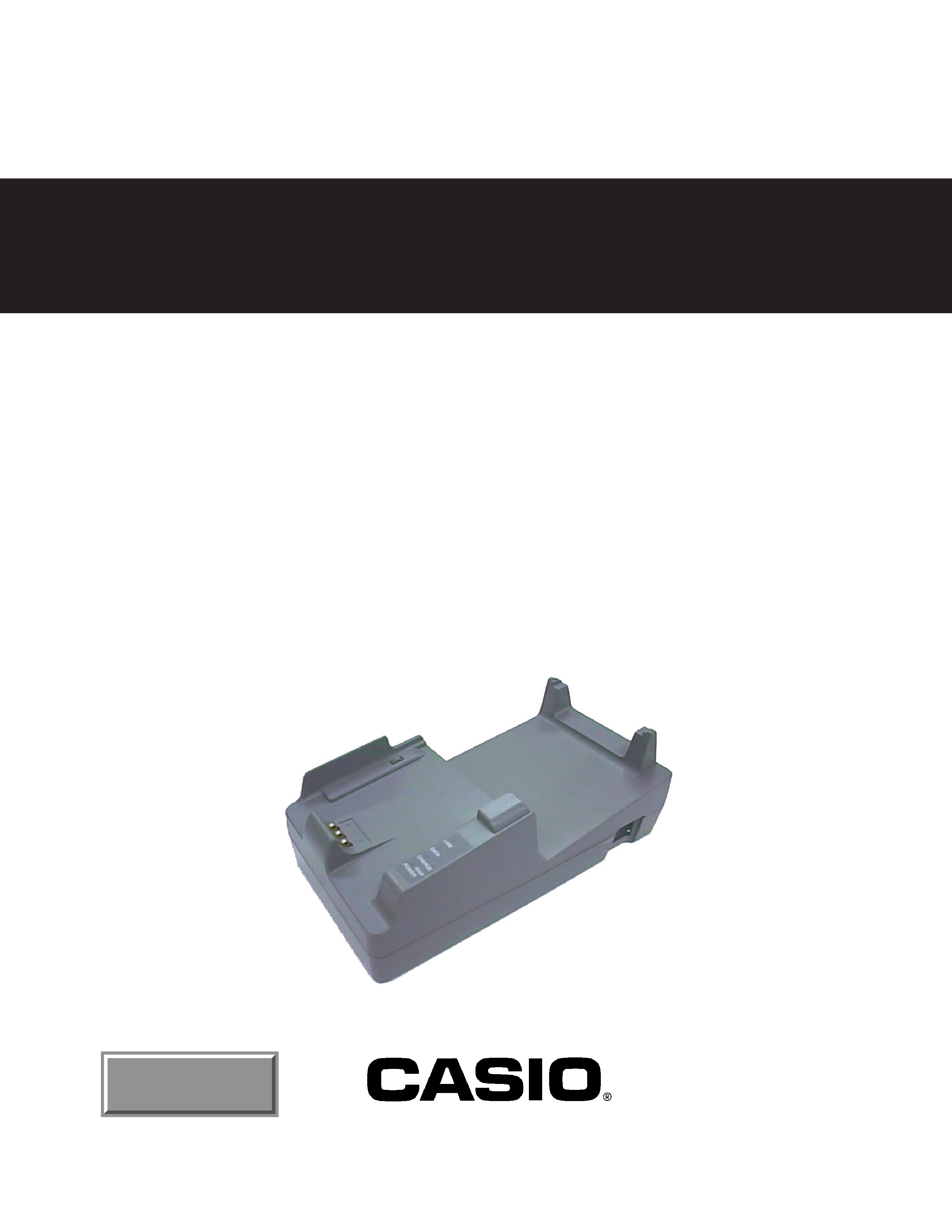
SATELLITE I/O BOX FOR IT-2000 HANDY TERMINAL
IT-2060 IO-E
(PX-957)
JAN 1998
SERVICE MANUAL
(without price)
INDEX

CONTENTS
1. SPECIFICATIONS ................................................................................................ 1
1.1 CPU ................................................................................................................. 1
1.2 Memory .......................................................................................................... 1
1.3 Interface ......................................................................................................... 1
1.4 Power Supply ................................................................................................ 1
1.5 Outer dimensions .......................................................................................... 1
1.6 Weight ............................................................................................................ 1
1.7 Environment data .......................................................................................... 1
1.8 Durability ........................................................................................................ 1
2. DIP SWITCH ......................................................................................................... 2
3. INTERFACE PIN ASSIGNMENT .......................................................................... 3
3.1 Interface to Host (RS-232C) .......................................................................... 3
3.2 Interface to Multi Drop (RS422 ) ................................................................... 3
3.3 Charging terminal ......................................................................................... 3
4. INTERFACE CABLE ............................................................................................ 4
4.1 Host PC to RS-232C ...................................................................................... 4
4.2 Multi Drop connection .................................................................................. 4
5. CONNECTION COMPONENTS ........................................................................... 5
5.1 Host PC, external machines -- Satellite I/O box ........................................ 5
5.2 Host PC -- Master I/O box -- Satellite I/O box ........................................... 5
5.3 Host PC -- Satellite I/O box .......................................................................... 6
6. ACTION MODE ..................................................................................................... 7
6.1 Active mode ................................................................................................... 7
6.2 Passive mode ................................................................................................ 9
7. SYSTEM DIAGRAMS ......................................................................................... 11
7.1 System diagram .......................................................................................... 11
7.2 PCB diagram ................................................................................................ 12
8. DISASSEMBLY ................................................................................................... 13
8.1 Separartion of the Upper case block and the Lower case block ............ 13
8.2 Disassembly of the Upper case block ....................................................... 13
8.3 Disassembly of the Lower case block ...................................................... 14
9. CIRCUIT DIAGRAMS ......................................................................................... 15
9.1 Curcuit diagram INDEX ............................................................................... 15
10. EXPLODED VIEW .............................................................................................. 25
11. PARTS LIST ........................................................................................................ 26

-- 1 --
1. SPECIFICATIONS
1.1 CPU
CPU: HITACHI SH7020 32 bit RISC
Clock: 18.432MHz
1.2 Memory
SRAM: 32Kbyte (256Kbit
× 2), 70 nS
EEPROM: 128K byte (1Mbit
× 1), 100 nS
(MASK ROM)
1.3 Interface
Interface to H/T (comforms to Irda Ver.1.0)
Purpose:
for data transfer to IT-2000
Communication speed: 9,600/38.4 k/115k bps
Transfer type:
Start-stop synchronous transmission
Transfer distance:
only when machines are in contact to each other.
Interface to Host (RS232C)
Purpose:
for connections of PC, Modem, Printer
Communication speed: 2,400/4,800/9,600/19.2 k/38.4 k/57.6 k/115.2k bps
Transfer type:
Start-stop synchronous transmission
I/F level:
SD (0)
+15 V ~ +5 V
SD (1)
15 V ~ 5 V
RD (0)
more than +3 V
RD (1)
less than 3 V
Interface to Multi Drop (RS422)
Purpose:
for Multi Drop connection of I/O Box
Communication speed: 9,600/ 38.4 k/115.2k bps
Transfer type:
Start-stop synchronous transmission
Total cable length:
1km
Connectability:
Maximum 8 units
× satellite I/O box
I/F level:
± 2 V ~ 5 V (differeutial voltage)
1.4 Power supply
Input Voltage:
DC12 V
± 4 %
Current consumption:
600 mA (MAX) (IT-2000 when recharging)
Output Voltage:
9.5 V ~ 13.2 V
Output Current:
500 mA
AC adaptor:
DT-825ADP-U (120VAC)
DT-825ADP-G (230VAC)
1.5 Outer dimensions approx. 220 mm (L)
× 110 mm (W) × 80 mm (H)
1.6 Weight
approx. 370 g
1.7 Environment data
Operating temperature:
0
°C ~ 40 °C
Storage temperature:
10
°C ~ 50 °C
1.8 Durability
MTBF 57,000 hours

-- 2 --
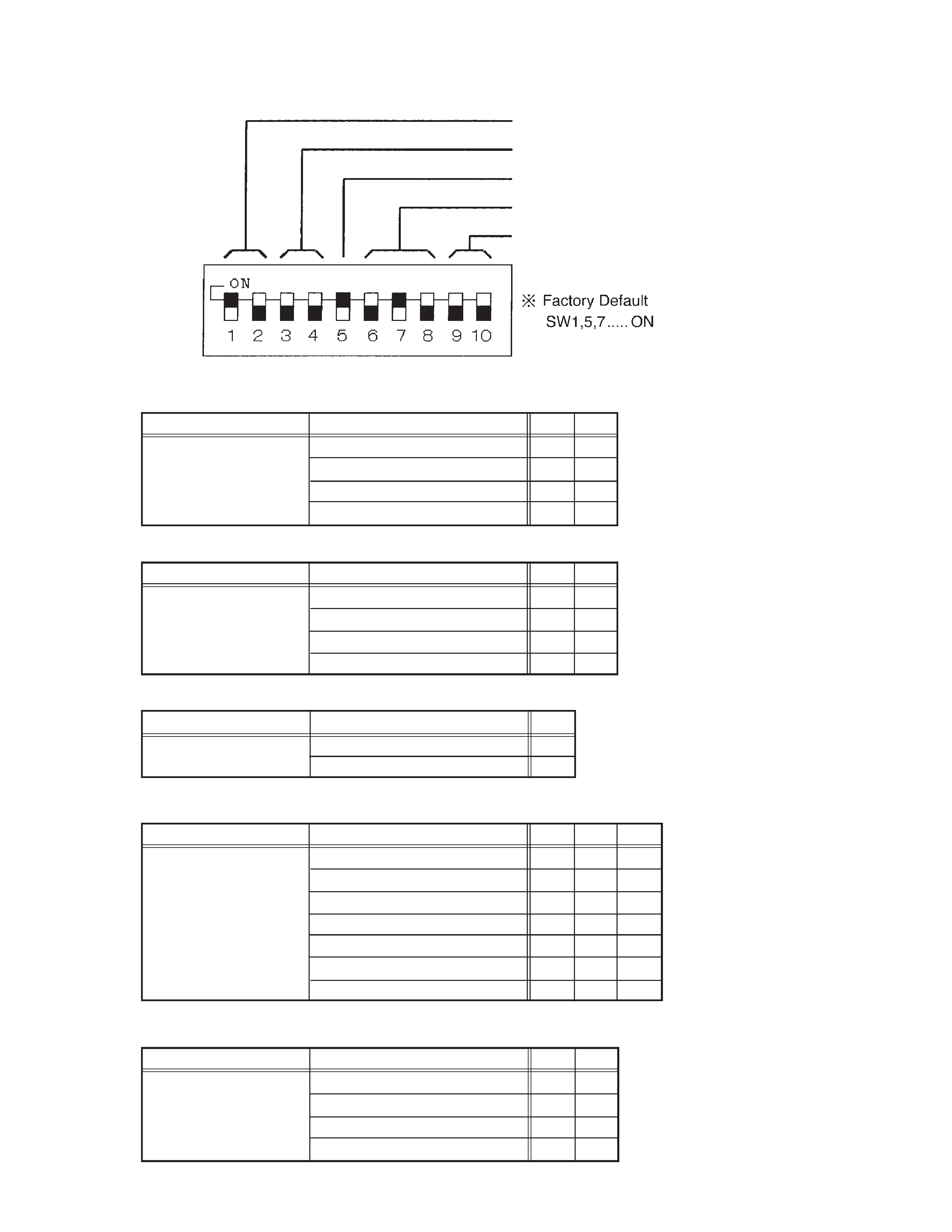
2. DIP SWITCH
Interface to H/T Communication speed
Connection Mode
Termination
Interface to Host Communication speed
Flow Control
SW
9
10
Off
off
off
Flow
X ON /X OFF
on
off
Control
RS/CS
off
on
Host Connection
on
on
SW
6
7
8
2,400 bps
off
off
off
4,800 bps
on
off
off
Interface to Host
9,600 bps
off
on
off
Communication speed
19.2 Kbps
on
on
off
38.4 Kbps
off
off
on
57.6 Kbps
on
off
on
115.2 Kbps
off
on
on
SW
3
4
Active Host Connection
off
off
Connection
Passive Multi Drop Connection
on
off
Mode
Through Download
off
on
Inhibition
on
on
SW
1
2
38.4 Kbps
off
off
Interface to H/T
115.2 Kbps
on
off
Communication speed
Off
off
on
Inhibition
on
on
SW
5
Termination
Termination off
off
Termination on
on
Interface to H/T communication speed
Connection Mode
Termination
Interface communication speed
Flow Control

-- 3 --
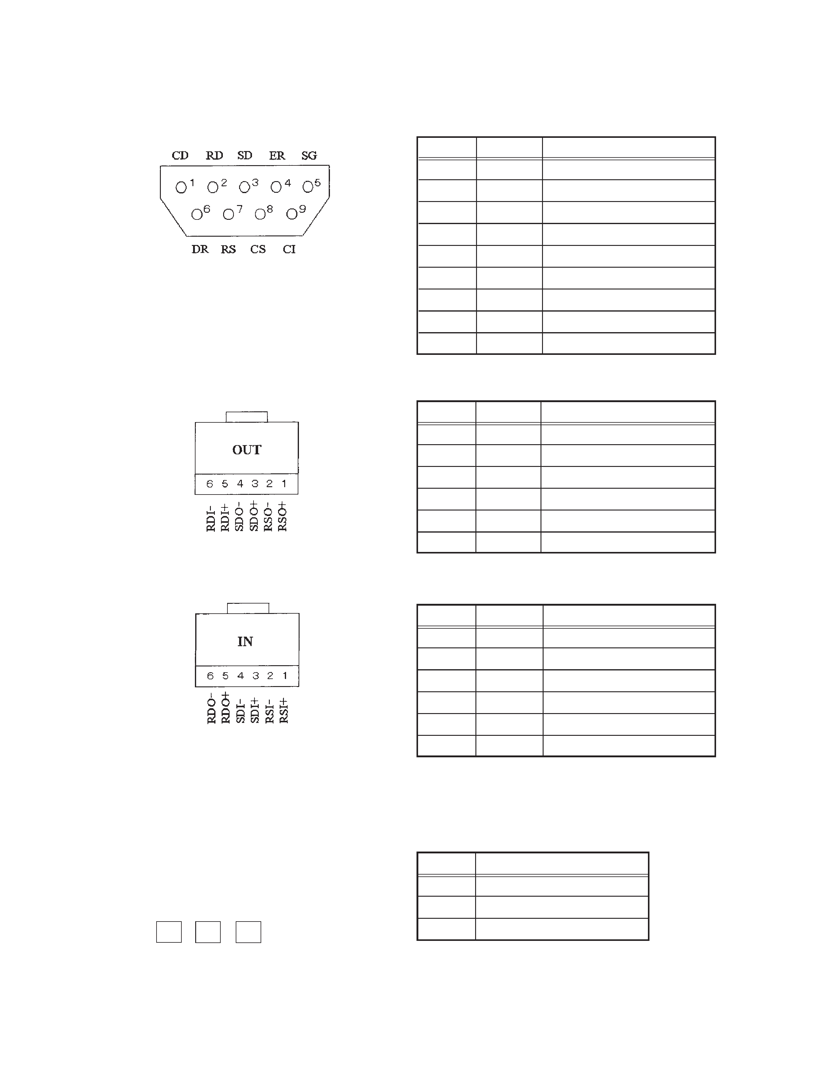
3. INTERFACE PIN ASSIGNMENT
3.1 Interface to Host (RS-232C)
D-Sub 9Pin (male)
3.2 Interface to Multi Drop (RS422)
6-wire Module connector
3.3 Charging terminal
PIN No.
Signal
Description
1
CD
Carrier detect
2
RD
Receive data
3
SD
Send data
4
ER
Equipment ready
5
SG
Signal GND
6
DR
Data set ready
7
RS
Request to send
8
CS
Clear to send
9
CI
Carrier indicater
PIN No.
Signal
Description
1
RSO+
Request to send output +
2
RSO
Request to send output
3
SDO+
Send data output +
4
SDO
Send data output
5
RDI+
Receive data input +
6
RDI
Receive data input
PIN No.
Signal
Description
1
RSI+
Request to send input +
2
RSI
Request to send input
3
SDI+
Send data input +
4
SDI
Send data input
5
RDO+
Receive data output +
6
RDO
Receive data output
Signal
Description
+
Charging terminal
GND
S
Charging ststus
+
S
