R
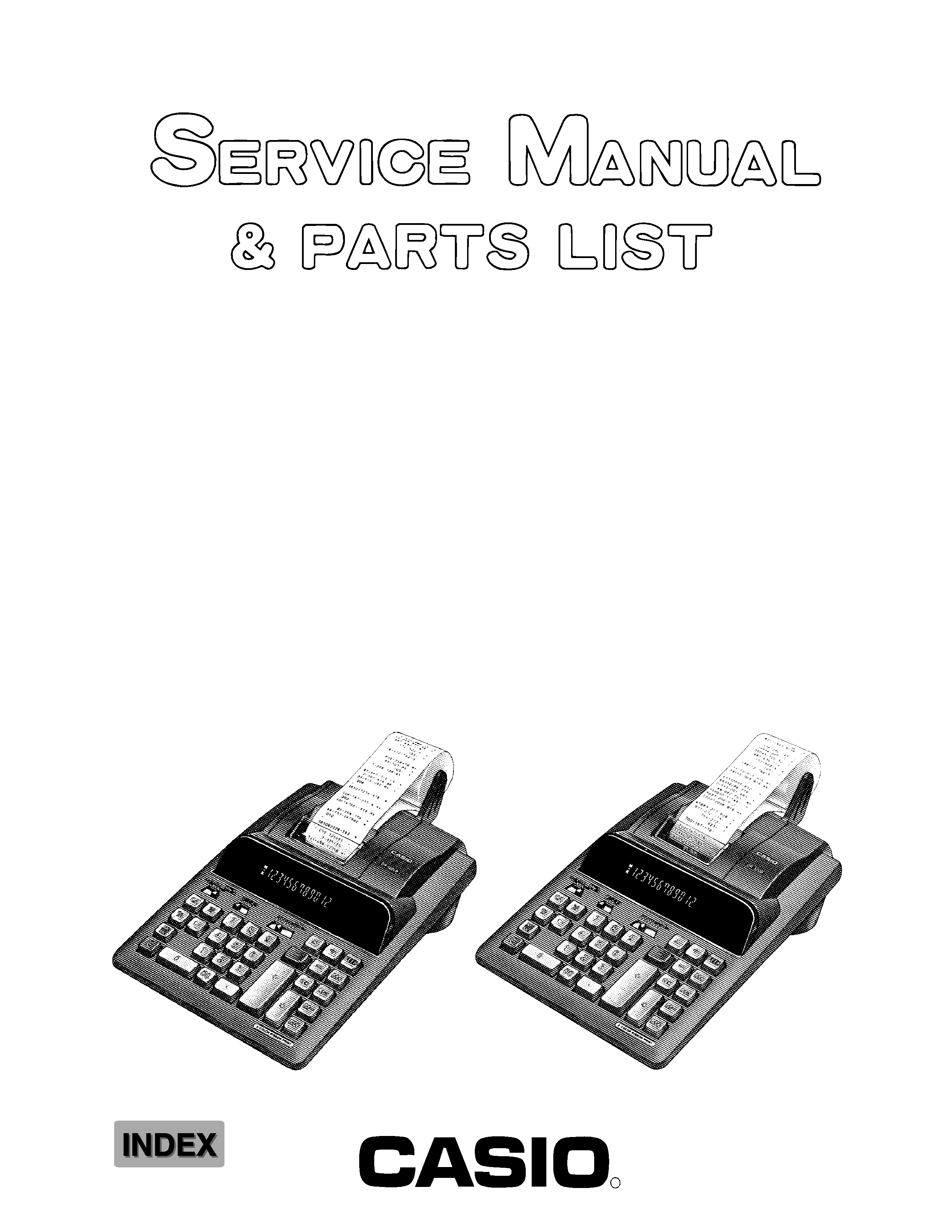
DR-120LB (ZX-517C)
DL-200L (ZX-517A)
DL-210L (ZX-517B)
DR-320B (ZX-517D)
JULY 1996
(without price)
DR-120LB
DR-320B

CONTENTS
1.
SPECIFICATIONS ......................................................................................................... 1
2.
BLOCK DIAGRAM ........................................................................................................ 1
3.
CPU (MN15418YCY) PIN FUNCTION ...........................................................................2
4.
DIAGNOSTIC ................................................................................................................ 3
5.
TROUBLESHOOTING .................................................................................................. 4
6.
DISASSEMBLY VIEW ................................................................................................... 5
7.
SCHEMATIC DIAGRAMS ............................................................................................. 6
8.
PARTS LIST ................................................................................................................ 10

-- 1 --
1. SPECIFICATIONS
Functions:
4 basic arithmetic operations (+, ,
×, ÷), constants for ×/÷, sub-total/
total/grand total, item counting, ADD mode calculations, repeat calcu-
lations, memory calculation, percentage calculations and various
kinds of practical calculations.
Decimal point:
Full floating, and fixed (0, 1, 2, 3, 4, or 6) with round off, round-up cut-
off.
Capacity:
12 digits
Ambient temperature range:
0
°C ~ 40 °C (32 °F ~ 104 °F)
Power supply:
(AC 120 V, 100/120 V, 230/240 V)
Rated current and voltage are printed on the calculator.
Dimensions:
75.1 (H)
× 212 (W) × 358 (D) mm
(3" H
× 8 3/8" W × 14 1/8" D) including roll-holder
Weight:
1.5 kg (3.3 lbs)
Consumable supplies:
Printer ribbon (RB-02 or GB-02)
Roll papaer (Width 58
× 60 ø mm)
The AC outlet must be located near the unit and must be easily accessible.
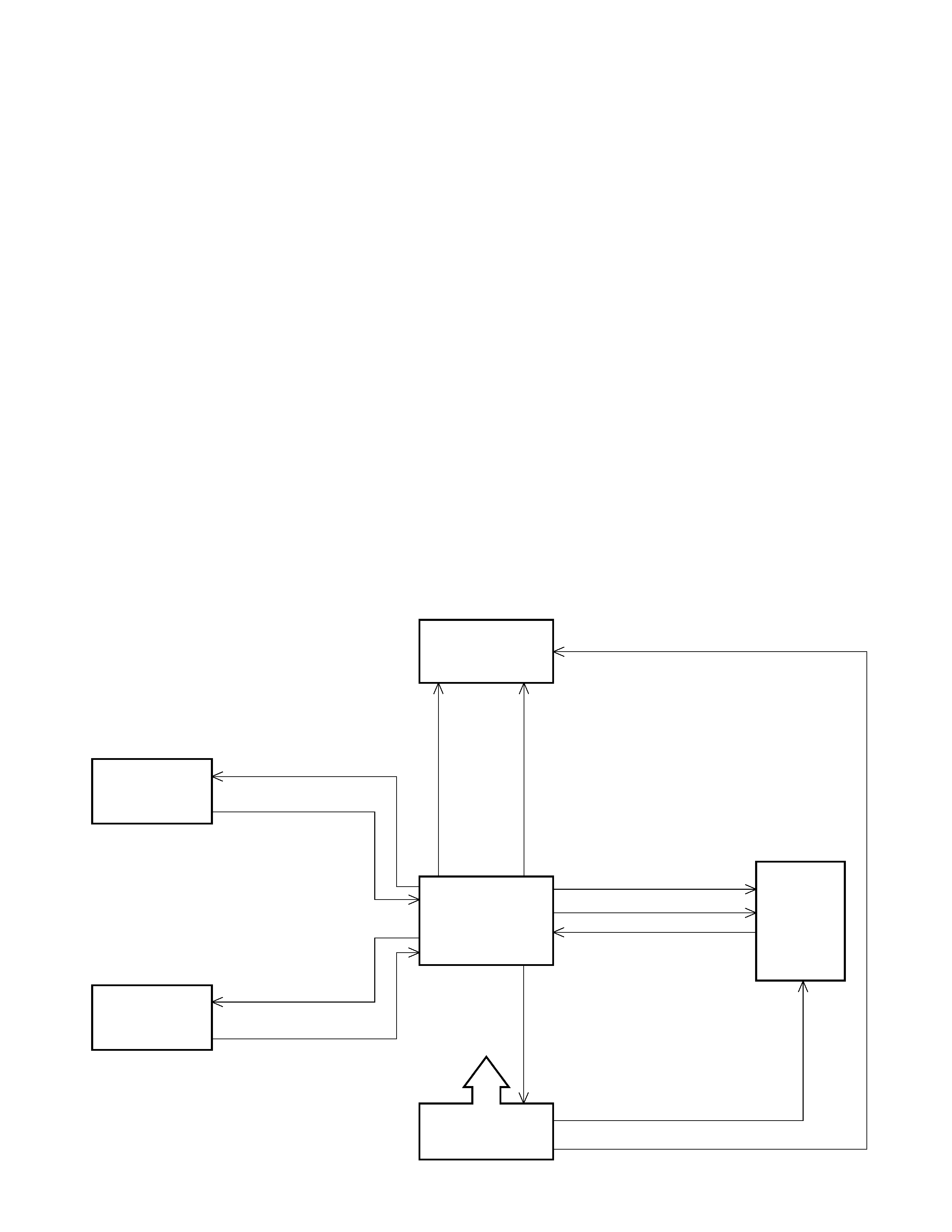
2. BLOCK DIAGRAM
Display tube
13-BT-144G
CPU
MN158418YCY
Power supply
circuit
Slide switch
Keyboard
Printer
M-80
VF1 (5.9 V, 100 mA), VF2 (2.0 V, 100 mA)
Ribbon shift signal
Character selective signal
Timing pulse
Digital signal
D1~D13
Motor control signal
VDD (32 V, 30 mA)
VSS (27 V, 30 mA)
Sent signal
S1~S7, SAP, SDP
SO1~SO7
SI1~SI3, SI5
KO1 ~ KO8
KI1 ~ KI6
VM (11 V, 200 mA)
VDD

-- 2 --
3. CPU (MN158418YCY) PIN FUNCTION
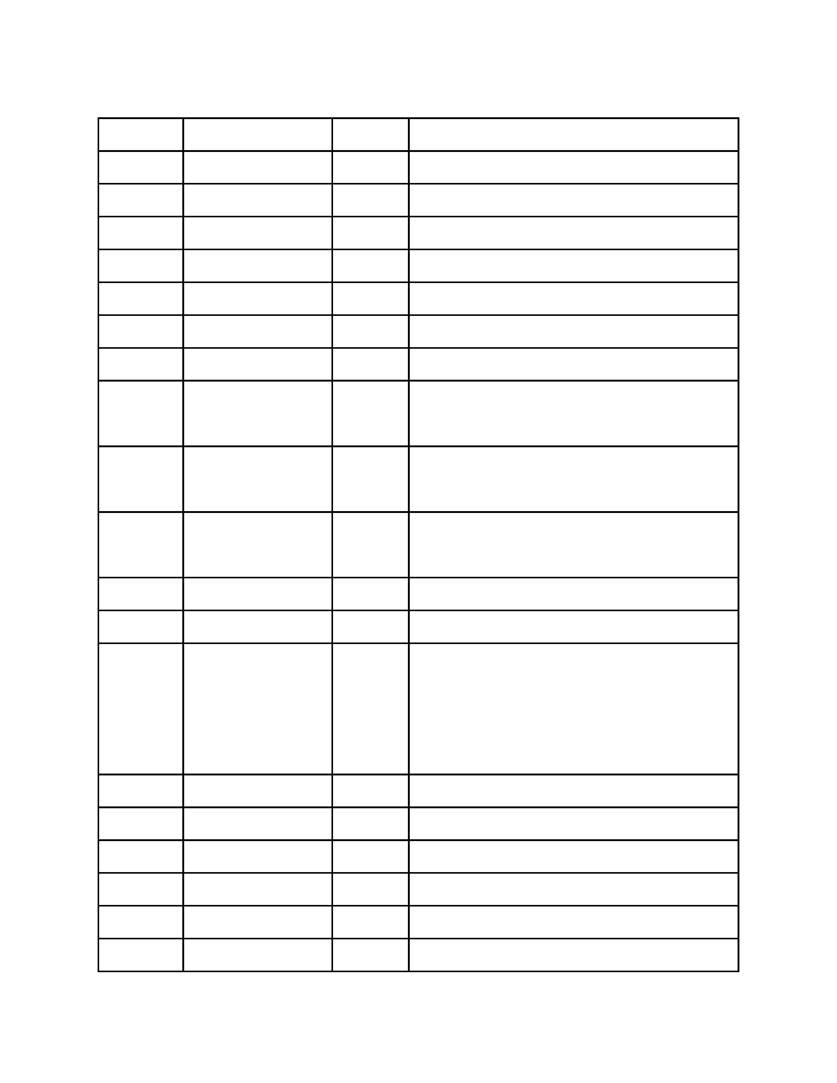
Pin No.
Signal
I / O
Function
1 ~ 7, 64
P00 ~ P13
Out
Common signal for keyboard
8 ~ 12
P20 ~ P22, P32, P33
In
Key signal from keyboard
13
IRQ
In
Timing pulse signal from printer
14
DEBIN
In
Reset pulse (Not used)
15
IRQCNT
In
Auxiliary timing (VDD)
16
P40
Out
Motor control signal
17
P41
Out
Ribbon shift signal for printer
18 ~ 30
P42, P43, P50 ~ P53,
Out
Character selective signal for printer
P70 ~ P73, P80 ~ P82
31, 32
P83, P90
Out
Segment signal for display,
Character selective signal for printer
33 ~ 39
P91 ~ P93
Out
Common signal for slide switch,
PA0 ~ PA3
Segment signal for display
40
P60
In
Input port (VDD)
41 ~ 43
P61 ~ P63
In
Signal from slide switch
44 ~ 56
PB0 ~ PB3,
Out
Digit signal for display
PC0 ~ PC3,
PD0 ~ PD3,
PE0
57
VPP
In
GND terminal
58
VDD
In
VDD terminal (+32 V)
59, 60
OSC1, OSC2
I/O
Clock signal for CPU
61
VSS
In
VSS terminal (+27 V)
62
SYNC
--
Not used
63
RST
In
Signal from slide switch, Reset signal

-- 3 --
STEP
1
2
3
4
5
6
7
8
9
10
11
12
13
14
15
16
17
18
19
20
21
22
23
PRINT
Paper feeding
NOTE
The character with "[ ]"
will be printed by red
ink.
Press the button 3
seconds continuously.
MODE SWITCHES
ON
F
6
ON
F
6
ON
F
6
ON
F
6
PRINT
F
6
PRINT
F
6
PRINT
F
6
PRINT CUT
6
PRINT
UP
4
PRINT
UP
3
PRINT
UP
2
PRINT
5/4
1
PRINT
5/4
0
PRINT
5/4 ADD
×
PRINT
5/4 ADD
×
PRINT
5/4 ADD
×
PRINT
5/4 ADD+
PRINT
5/4 ADD+
ITEM+
5/4 ADD+
ITEM+/ 5/4 ADD+
ITEM+/ 5/4 ADD+
ITEM+/ 5/4 ADD+
OFF
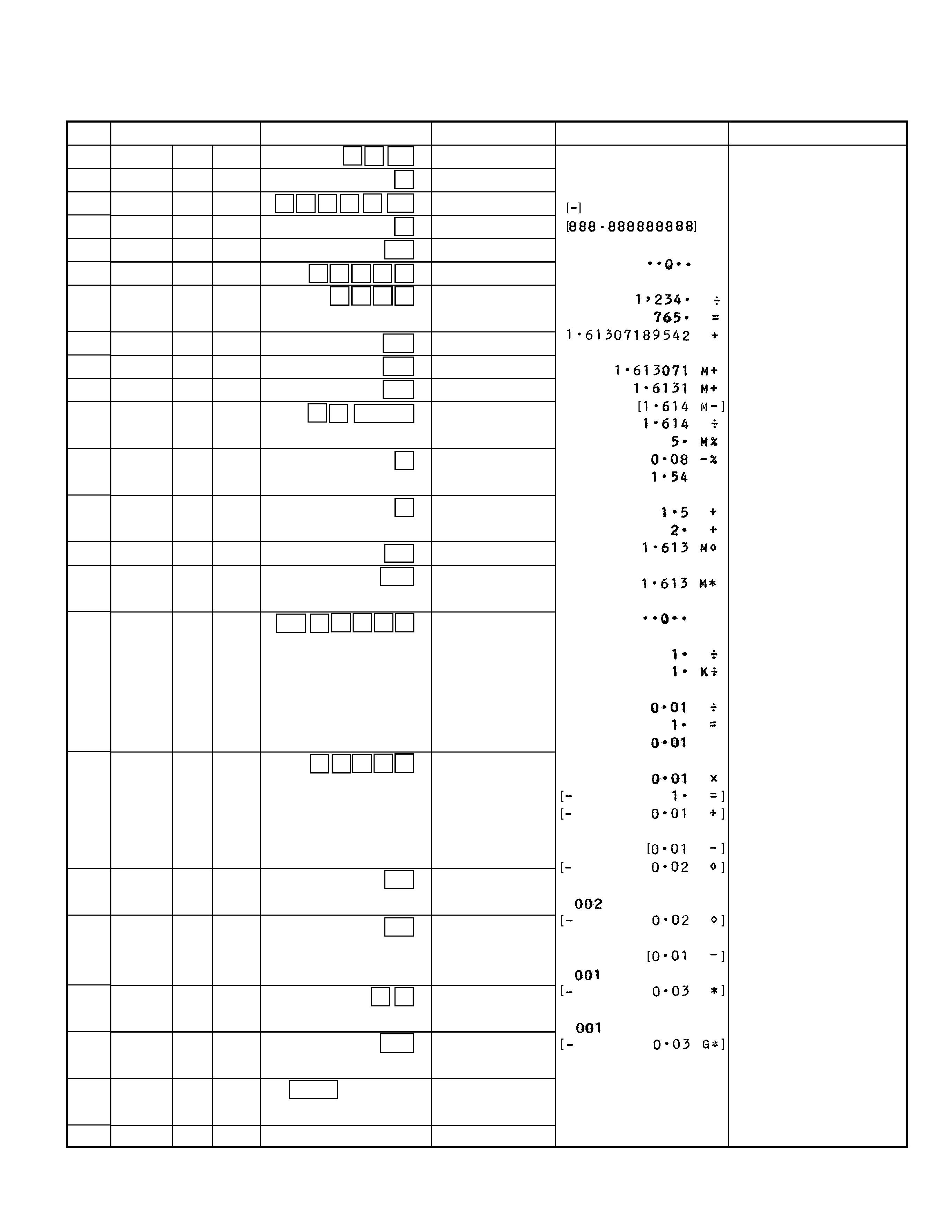
4. DIAGNOSTICS
OPERATION
1 0 00
C
8
÷ 9 % /#
CA
1 2 3 4
÷
7 6 5 +
M+
M+
M
÷ 5 MU/MD
+
+
M
Mi
CA 1
÷ ÷ 1 =
× 1 1
/#
/#
i
Gi
FEED
v
DISPLAY
1000.
0.
-888.888888888
-888.88888888
0.
1234.
1.61307189542
M
1.613071
M
1.6131
M
1.614
M
1.54
M
3.1
M
5.
1.613
1.613
K
0.01
0.02
0.02
0.02
0.03
0.03
NO Display
