INTRODUCTION
This SERVICE MANUAL is intended to provide the serviceman with a basic knowledge of
the NP-1530 and has been compiled to serve as a handy reference for his work in the field.
The NP-1530 is designed to accommodate the following for fully automated copy work:
1. Stapler Sorter-B1
2. MS-Al
3. ADF-Al
4. Control Card V
A separate service manual is made available for the Stapler
MS-AI, ADF-AI, and
Control Card V; see the respective manuals for discussions of each.
In CHAPTER 1 GENERAL DESCRIPTION, a brief discussion of the NP-1530 `s features,
diagrams of its parts, and an explanation of its operation are given.
CHAPTER 2 COPYING PROCESS deals with the inner working of the NP-1530 which are
associated with the generation of copies.
CHAPTER 3 OPERATIONS AND TIMING explains how the NP-1530's electrical and
mechanical systems are related to each other with respect to functions and timing of
operations.
In CHAPTER 4 MECHANICAL SYSTEM, the NP-1530's mechanical system is discussed as
to its operation, disassembly, reassembly, and adjustment.
CHAPTER 5 INSTALLATION gives step-by-step instructions for installing the NP-1530
together with checks to make for each step.
CHAPTER 6 MAINTENANCE AND SERVICING contains tables of replacement parts and
consumables.
In addition to the above chapters, this SERVICE MANUAL contains a set of appendixes
consisting of a general timing chart and general circuit diagrams.
A separate document entitled SERVICE HANDBOOK is also available for troubleshooting
problems in the NP-1530.
Note:
The contents of this manual may be updated from time to time to reflect improvements
rendered to the NP-1530; a Service Information Bulletin will be issued as necessary to cover
major changes.
All servicemen are expected to be thoroughly familiar with the information contained in
this manual, SERVICE HANDBOOK, and Service Information Bulletins, for quick response.
1992 CANONINC.
CANON NP.1530 REV.0 FEB.1992


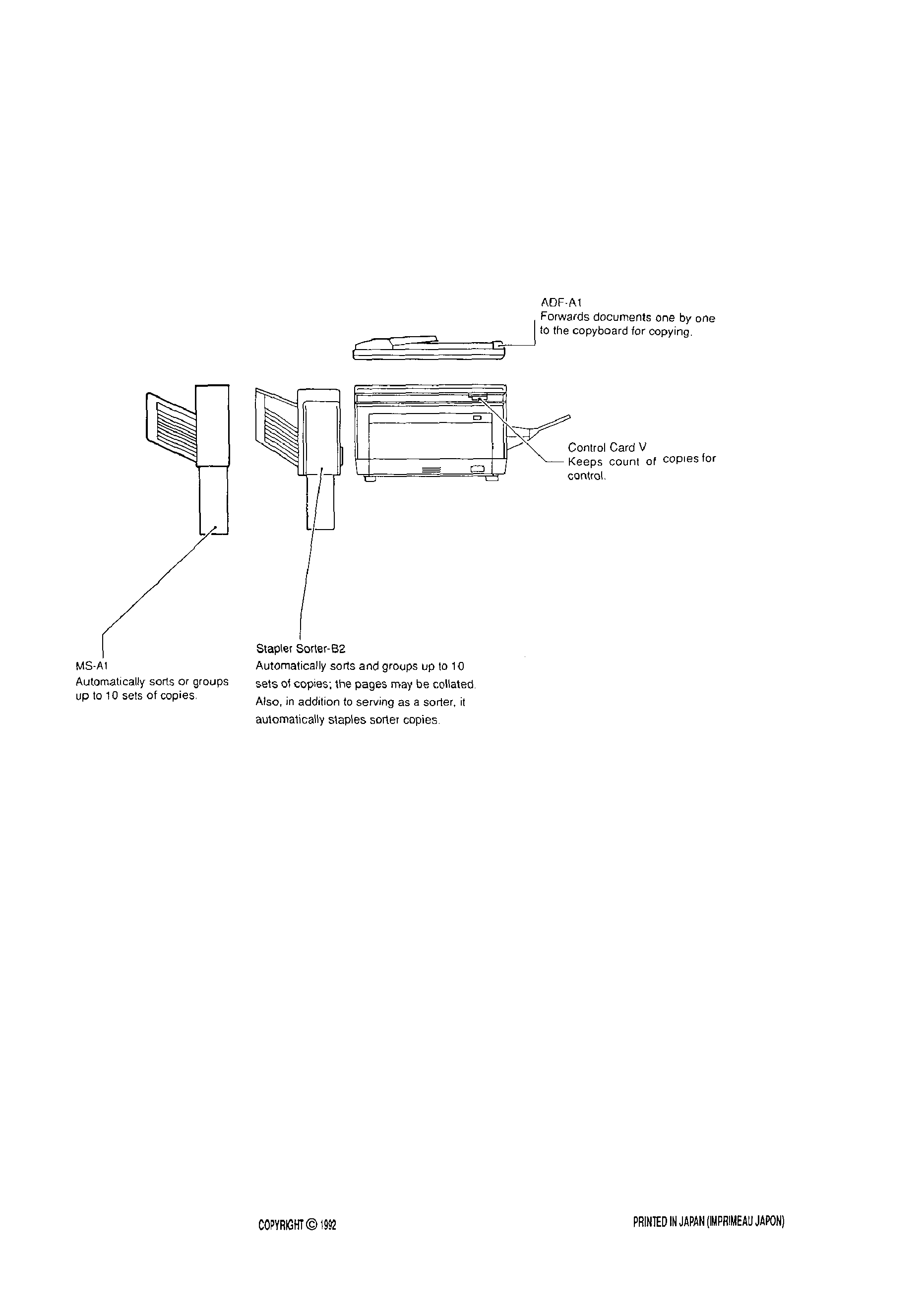
System Configuration
See the diagram below for the NP-1530's typical system configuration.
CANON INC.
copy
CANON NP.1530REY.l NOV.1992

I.
FEATURES.. .......................................
l-1
II. SPECIFICATIONS ..............................
A. Type.. ..............................................
l-2
B. System.. ..........................................
l-2
C. Performance.. .................................
D. Others.. ...........................................
Ill. NAMES OF PARTS ............................ l-5
A. External View.. ................................
B. Cross Section.. ................................
V.
D. Two-Sided Copying ......................... l-9
E. Overlay Copy Operation .................
F. Auto Start.. .....................................
G. Replacing the CT Unit
WARNING INDICATOR AND
REQUIRED ACTION.. .......................
0
A. JAM Indicator.. .............................. l-1 0
B. ADD PAPER Indicator ...................
1
C. ADD TONER Indicator.. ................
2
IV. OPERATION.. .....................................
l-7
A. Control Panel.. ................................ l-7
B. Basic Copying Operation ................ l-8
C. Pick-up from Multifeeder.. ............... l-8
D. CONTROL CARD Indicator ........... l-1 2
VI. DAILY INSPECTION TO BE
FORMED BY THE CUSTOMER.. ...... l-1 3
l. IMAGE
PROCESS . .
2-l
A. Outline
.
.
.
.
.
.
.
.
2-l
B. Electrostatic Lantent Image
Formation Block
2-2
C. Step1 Pre-Exposure
2-2
D. Step2 Primary Corona
2-2
E. Step3 Scanning Exposure
2-3
F. Step4 Developing ........................... 2-3
G. Step5 Transfer ................................ 2-4
H. Step6 Separation.. .......................... 2-4
I.
Step7 Fixing ................................... 2-5
J. Step8 Drum Cleaning ..................... 2-5
II. AUXILIARY PROCESSES.. ................. 2-5
A. Blank Exposure.. ............................
B. Ozone Filter ...................................
I.
BASIC OPERATION
3-1
EXPOSURE SYSTEM
Ill. IMAGE FORMATION SYSTEM
IV. PAPER TRANSPORT
V.
POWER SUPPLY
3-35
VI. SERVICE MODE
3-37
VII. SELF DIAGNOSIS
3-43
CANONINC
CANON
FEB.1992

EXTERNALS ......................................
4-1
A. External Covers.. ..........................
Control Panel ...............................
C. Copyboard Cover.. .......................
Fans.. ...........................................
II. DRIVE SYSTEM.. ............................... 4-5
A. Scanner Drive Assembly .............. 4-5
B. Main Motor Assembly ..................
FEEDER SYSTEM ............................. 4-9
A. Pick-up Assembly ......................... 4-9
Feeder Assembly.. ...................
4
IV. EXPOSURE SYSTEM ....................
A. Exposure Assembly.. ..................
B. Blank Assembly ..........................
V.
CORONA SYSTEM .......................... 4-18
A. Drum Unit.. ..................................
B. Primary/Transfer Corona
Assembly.. ................................... 4-19
VI. DEVELOPMENT
SYSTEM.. ............
A. Developing Assembly .................
VII. FIXING SYSTEM ............................. 4-24
A. Fixing Assembly ........................... 4-24
I.
LOCATION.. ........................................
UNPACKING AND INSTALLING THE
COPIER ..............................................
A.
Unpacking .................................... 5-2
B.
Mounting the Drum ....................... 5-4
C.
Checking the Operation ............... 5-5
D.
Adding Toner ................................ 5-6
E.
Checking the Image ..................... 5-7
SETTING THE CASSETTE SIZE.. ....
IV. SETTING THE CT UNIT ................... 5-13
RELOCATING THE COPIER ..........
VI. SETTING CONTROL CARD V.. ......
VII. ATTACHING THE DOCUMENT
HOLDER.. .........................................
5-17
PERIODICALLY REPLACED
BASIC PROCEDURE FOR PERIODIC
PARTS . . . . . . . . . . . 6-1
SERVICING
6-3
II. DURABLE PARTS
6-2
IV. PERIODIC SERVICING
SCHEDULE
6-4
GENERAL TIMING CHART
A-l
G.
LIST OF SIGNALS/COMMANDS . . . ..A-3
GENERAL CIRCUIT DIAGRAM A-5
H.
DC CONTROLLER CIRCUIT
I.
DIAGRAM . .
A-7
J.
AE SENSOR CIRCUIT
DIAGRAM . . . .
A-l 2
AC DRIVER/DC POWER SUPPLY
CIRCUIT DIAGRAM
A-13
PRE-EXPOSURE LAMP CIRCUIT
DIAGRAM
A-14
HVT CIRCUIT DIAGRAM.. .............. A-15
OF SPECIAL TOOLS ............. A-17
LIST OF SOLVENT AND
MATERIALS
A-18
1932 CANONINC.
CANON NP.1530REY.0 FEB.1992
