SPEAKER SYSTEM
SX-AVR1700
SX-AV1700
SX-C1700
SX-R1700
S/M Code No. 09-993-328-1N2
Y
Y
Y
Y
SERVICE MANUAL
DA
TA
SX-AV1700
SX-R1700
SX-C1700
aiwa
aiwa
aiwa
aiwa
aiwa

2
SPECIFICATIONS
SX-AV1700
Speaker
2 way 3 speakers
Woofer: 100 mm, cone type
Tweeter: 60 mm, cone type
Passive radiator: 100 mm
Impedance
8 ohms
Maximum input power
75 W (peak)
Dimensions (W x H x D) 170 x 500 x 205 mm (63/4 x 193/4 x 81/8 in.)
Weight
2.8 kg (6 lbs 3 oz)
· Design and specifications are subject to change without notice.
SX-C1700
Speaker
Full-range: 100 mm x 2, cone type
Impedance
8 ohms
Maximum input power
75 W (peak)
Dimensions (W x H x D) 430 x 120 x 175 mm (17 x 43/4 x 7 in.)
Weight
2.7 kg (5 lbs 15 oz)
· Design and specifications are subject to change without notice.
SX-R1700
Speaker
Full-range: 100 mm x 1, cone type
Impedance
8 ohms
Maximum input power
75 W (peak)
Dimensions (W x H x D) 120 x 230 x 175 mm (43/4 x 91/8 x 7 in.)
Weight
1.9 kg (4 lbs 3 oz)
· Design and specifications are subject to change without notice.
REF. NO
PART NO.
KANRI
DESCRIPTION
NO.
1
8Z-AS3-906-010
IB,Y(9L)C
ACCESSORIES LIST

3
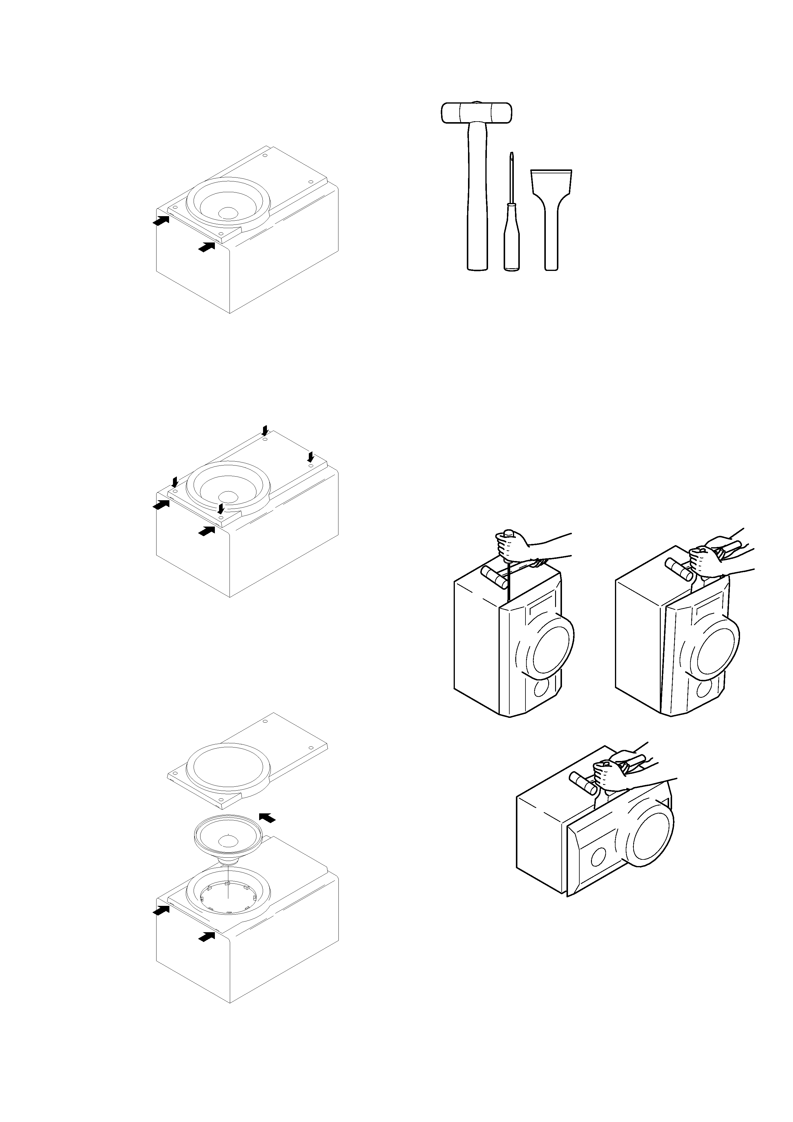
SPEAKER DISASSEMBLY INSTRUCTIONS
Insert a flat-bladed screwdriver into the position indicated by the
arrows and remove the panel. Remove the screws of each speaker
unit andthen remove the speaker units.
Remove the grill frame and four pieces of rubber caps by pulling
out with a flat-bladed screwdriver. Remove the screws from hold
where installed rubber caps. Insert a flat-bladed screwdriver into
the position indicated by the arrows and remove the panel. Re-
move the screws of each speaker unit and then remove the speaker
units.
Insert a flat-bladed screwdriver into the position indicated by the
arrows and remove the panel. Turn the speaker unit to counter-
clockwise direction while inserting a flat-bladed screwdriver into
one of the hollows arround speaker unit, and then remove the speaker
unit. After replacing the speaker unit, install it turnning to clock-
wise direction unitil "click" sound comes out.
Type.1
Type.3
Type.2
TOOLS
1 Plastic head hammer
2 (-) flat head screwdriver
3 Cut chisel
How to Remove the PANEL, FR
1.
Insert the (
-) flat head screwdriver tip into the gap
between the PANEL, FR and the PANEL, SPKR. Tap
the head of the (
-) flat head screwdriver with the plastic
hammer head, and create the clearance as shown in Fig-1.
2.
Insert the cut chisel in the clearance, and tap the head of
the cut chisel with plastic hammer as shown in Fig-2, to
remove the PANEL, FR.
3.
Place the speaker horizontally. Tap head of the cut
chisel with plastic hammer as shown in Fig-3, and
remove the PANEL, FR completely.
Type.4
Fig-1
Fig-2
Fig-3
How to Attach the PANEL, FR
Attach the PANEL, FR to the PANEL, SPKR. Tap the four
corners of the PANEL, FR with the plastic hammer to fit the
PANEL, FR into the PANEL, SPKR completely.
1
2
3

920074
Printed in Singapore
211, IKENOHATA 1CHOME, TAITO-KU, TOKYO 110-8710, JAPAN TEL:03 (3827) 3111
SPEAKER PARTS LIST
REF. NO
PART NO.
KANRI
DESCRIPTION
NO.
1
8Z-AS3-001-010
GRILLE,FRAME ASSY
2
8Z-AS3-602-010
SPKR, 100
3
8Z-AS3-604-010
SPKR, 100
4
8Z-AS3-606-010
SPKR, TW 50
5
8Z-AS3-005-010
TERMINAL,ASSY
6
88-AS1-609-010
SPKR, CORD 30M
SX-AV1700
REF. NO
PART NO.
KANRI
DESCRIPTION
NO.
1
8Z-AS4-001-010
GRILLE,FRAME ASSY
2
8Z-AS4-602-010
SPKR, 100
3
8Z-AS4-003-010
TERMINAL,ASSY
SX-C1700
REF. NO
PART NO.
KANRI
DESCRIPTION
NO.
1
8Z-AS5-601-010
SPKR, 100
2
8Z-AS5-001-010
GRILLE,FRAME ASSY
3
8Z-AS5-005-010
TERMINAL,ASSY
SX-R1700
